1
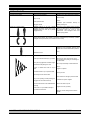
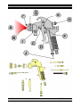
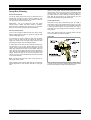
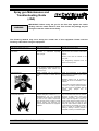
MAINTENANCE & TROUBLESHOOTING
PAGE 1
Spray gun Maintenance and
Troubleshooting Guide
(JGA)
WARNING
IMPORTANT: Before using the gun for the first time, tighten the needle
packing until the needle starts to bind. Then loosen the packing nut just
enough so that the needle moves freely.
The following hazards may occur during the normal use of this equipment. Please read the
following chart before using the equipment.
Area
Hazard
Safeguard
Tells where hazards may occur.
Tells where hazard is.
Tells how to avoid the hazard
Spray AreaFire Hazard
Solvent and coatings can be highly
flammable or combustible especially
when sprayed.
Adequate exhaust must be provided to
keep air free of accumulations of flammable
vapours.
Smoking must never be allowed in the
spray area.
Fire extinguishing equipment must be
present in the spray area.
Solvent Spray
During cleaning and flushing, solvents
can be forcefully expelled from fluid and
air passageways. Some solvents can
cause eye injury.
Wear eye protection
Toxic Substances
Certain materials may be harmful if
inhaled, or if there is contact with the
skin.
Follow the requirements of the Material
Safety Data Sheet supplied by your coating
material manufacturer.
Adequate exhaust must be provided to
keep the air free of accumulations of toxic
materials.
Use a mask or respirator whenever there is
a chance of inhaling sprayed materials.
This mask must be compatible with the
material
being
sprayed
and
its
concentration.
Explosion HazardIncompatible Materials
Halogenated Hydrocarbon solvents - for
example: Methylene Chloride and 1,1,1 Trichloroethane are not chemically
compatible with the aluminium which may
be used in many system components.
The chemical reaction caused by these
solvents reacting with aluminium can
become violent and lead to an equipment
explosion.
MAINTENANCE & TROUBLESHOOTING
Guns with stainless steel fluid passages
may be used with these solvents. However,
Aluminium is widely used in other spray
application equipment - such as material
pumps, cups and regulators, valves, etc.
Check all other equipment items before use
and make sure they can also be used
safely with these solvents. Read the label
or data sheet for the material you intend to
spray. If in doubt as to whether or not a
coating or cleaning or cleaning material is
compatible, contact your material supplier.
PAGE 1
MAINTENANCE & TROUBLESHOOTING
PAGE 2
SPRAY FAULTS
Condition
Cause
Correction
Improper spray pattern
Gun Improperly adjusted.
Readjust gun, follow instructions carefully.
Clean air cap.
Dirty air cap
Clean
Fluid tip obstructed
Sluggish needle
Lubricate (see lubrication section) or
loosen packing nut.
Heavy top or bottom pattern
Material build-up on air cap, partially
plugged horn holes, centre holes or jets.
Material build-up on fluid tip or partially
plugged fluid tip
Soak cap or tip in suitable solvent and wipe
clean. To clean orifice, use a broom straw
or toothpick. Never use a wire or hard
instruments. This damages holes and
distorts spray pattern.
Heavy right or left side pattern
Note: To determine where material build-up is, invert cap and test spray. If pattern shape
stays in same position, the condition is caused by material build-up on fluid tip. If pattern
changes with cap movement, the condition is in the air cap.
Heavy centre pattern
Too much material
Reduce fluid flow by turning fluid needle
adjusting screw clockwise. Reduce fluid
pressure or increase atomisation pressure.
Thin
Material too thick
Intermittent or ‘fluttering’spray fan
Loose fluid tip
Tighten to 17 Nm (150 ibf/in)
Fluid tip not seated correctly in gun head
Remove tip, clean components, check
cone seating on tip and gun for damage or
contamination
Gun (with cup) tipped at excessive angle.
Do not tip excessively or rotate fluid tube.
Obstructed fluid passage or hose.
Clean
Loose or cracked fluid tube in cup or
tank.
Tighten or replace
Insufficient fluid in cup or pressure tank.
Fill cup or tank
Too heavy fluid for suction feed.
Thin material or change to pressure feed
Dry or worn packing or loose packing nut.
Lubricate or replace. Tighten
Plugged vent on suction feed cup.
Gun fluid inlet loose or not sealed/seated
correctly
Clean vent hole in cup lid.
Tighten to 8 Nm (70 lbf/in)
Fluid hose or cup not fitted correctly to
gun fluid inlet connector
Remove, check mating surfaces and retighten
MAINTENANCE & TROUBLESHOOTING
PAGE 2
MAINTENANCE & TROUBLESHOOTING
PAGE 3
SPRAY FAULTS
Condition
Cause
Correction
Split spray pattern
Not enough material
atomisation pressure
Excessive bounce-back
Too much atomisation air pressure
Reduce air pressure
Gun too far from surface
Check distance (normally 6-8”)
Improper technique i.e. arcing, & fanning
the gun
Move at moderate pace, parallel to work
surface
Too much material flow
Adjust gun or reduce fluid pressure
Material too thin
Mix properly or apply light coats
Gun tilted on an angle
Hold gun at right angle to work and adapt
to proper gun technique
Gun too far from surface
Check distance (normally 6-8”)
Too much air pressure
Reduce air pressure and check spray
pattern
Improper thinner being used
Follow paint
instructions
Gun too close to surface
Check distance (normally 6-8”)
Air pressure too low
Increase air pressure or reduce fluid
pressure
Improper thinner being used
Follow paint
instructions
manufacturers
mixing
Material not properly mixed
Follow paint
instructions
manufacturers
mixing
Surface rough, oily, dirty
Properly clean and prepare
or
too
high
Reduce air pressure or increase fluid flow
by turning fluid needle adjusting screw
counterclockwise
or
increase
fluid
pressure on pressure feed container.
FINISH FAULTS
Runs and sags
Thin, sandy coarse finish drying before it
flows out.
Thick dimpled finish “orange peel”. Too
much material coarsely atomised.
MAINTENANCE & TROUBLESHOOTING
manufacturers
PAGE 3
mixing
MAINTENANCE & TROUBLESHOOTING
PAGE 4
MAINTENANCE & TROUBLESHOOTING
PAGE 4
MAINTENANCE & TROUBLESHOOTING
PAGE 5
GUN FAULTS
Condition
Cause
Correction
Will not spray
No air pressure at gun
Check air supply and air lines
Internal mix or pressure feed air cap used
with suction feed
Change to proper suction feed air cap
Fluid pressure too low with internal mix
cap and pressure tank
Increase fluid pressure at tank
Fluid needle adjusting screw not open
enough
Open fluid needle adjusting screw
Fluid too heavy for suction feed
Thin material or change to pressure feed.
Incorrect needle fitted to gun
Check tip/needle selection chart and fit
correct item
Excessive needle wear
Replace with new needle
Excessive fluid tip wear
Replace with new fluid tip
Air valve contaminated and not correctly
seating
Remove valve and thorougly clean valve
shaft and seating surfaces
Air Valve seal damaged or missing
Replace
Fluid tip not fitted correctly in gun head
Tighten to correct torque
A
A
A
A
Gun ‘spits’paint when triggering on
and off
Small air leak from air cap when
gun is not triggered
Gun ‘spits’paint when triggering on
due to paint build-up inside air cap
between spraying operations
Fluid tip/needle leakage
Check for damage or blockage
Slow fluid leak from fluid tip and
needle seat
B
Major fluid leak or fluid jetting from
fluid tip and needle seat
B
Fluid Tip internal seat scored, damaged or
worn
Replace
Fluid needle external profile damaged or
worn
Replace
Contamination on needle or tip mating
surfaces preventing good seal
Thoroughly clean
Incorrect fluid tip for fluid needle fitted to
gun
Check tip/needle selection chart and fit
correct item
Sluggish needle
Lubricate packing
Tight packing nut
Adjust
Contamination on needle or tip mating
surfaces preventing good seal
Remove tip and needle and thoroughly
clean
Incorrect fluid tip for fluid needle fitted to
gun
Check tip/needle selection chart and fit
correct item
Fluid needle stuck or ‘binding up’
Remove and clean fluid needle shaft, or
lubricate needle packing or loosen needle
packing
MAINTENANCE & TROUBLESHOOTING
PAGE 5
MAINTENANCE & TROUBLESHOOTING
PAGE 6
GUN FAULTS
Condition
Cause
Correction
Paint build-up on fluid tip
Fluid tip not fitted correctly in gun head
Tighten to correct torque
B
Fluid tip/needle leakage
Check for damage or blockage
Paint build-up on Air cap
Damaged air cap holes
Replace with new Air cap
Gradual build-up of bounce-back on gun
head
Thorougly clean
Slow fluid leak from needle packing
Fluid needle packing worn or loose
Tighten or replace as necessary
Air valve sluggish or slow to turn
on/off when trigger is
pulled/released
Air valve stem bent
Replace damaged component
Contamination on air valve stem
Remove and clean
Air leak from around air valve stem
Air valve seal damaged or missing
Replace
Air valve will not operate (air valve
stem will not fully slide into valve
body) when trigger is pulled
Air valve stem bent
Remove air valve and replace damaged air
valve stem
Contamination on air valve stem
Remove air valve and thoroughly clean
Air valve stem bent
Replace damaged component
Contamination on air valve stem
Remove and clean
Contamination on trigger bearing screw
Remove and clean
B
C
D
D
D
Stiff trigger action
E
Contamination on fluid needle shaft
Remove and clean
Fluid needle packing too tight
F
Air leak from fluid needle exit point
in top of handle
Seal damaged or missing
Loosen packing nut
Replace
Air cap retaining ring will not rotate
Contamination on retaining threads
Soak gun head in solvent to soften paint
Deformed or damaged retaining ring
Cut retaining ring off of gun (probably
replace retaining ring and baffle)
Internal O ring swollen or broken
Replace O ring
Paint contamination on threads
Remove and thoroughly clean
Fluid tip or air baffle incorrectly fitted
Remove, check components for damage
and refit correctly
Air baffle chinmey damaged
Replace air baffle
Air leak from baffle seal
Baffle seal swollen or damaged
Replace
Unable to turn air control valve on
handle of gun
Internal O ring swollen or broken
Replace O ring
Paint contamination on threads
Remove and thoroughly clean
G
H
Unable to turn fan control knob on
top rear of gun
Unable to get round spray
H
I
J
MAINTENANCE & TROUBLESHOOTING
PAGE 6
MAINTENANCE & TROUBLESHOOTING
Spray Gun Cleaning
Suction Feed Clean Up:
Turn off air supply. Disconnect cup from lid. Raise tube out of
material and pull trigger to allow remaining material to drain
back into the cup. Then empty the cup of material. Clean the
cup, lid and tube. Add some thinner to cup.
Reassemble - Turn on air supply and spray with proper
cleaning solvent. Repeat with clean solvent if necessary.
Remove solvent, disconnect gun, remove air cap and clean.
Wipe gun and cup with cleaning solvent dampened rag.
Pressure Feed Clean Up:
First, turn off air supply to material source (cup, tank or pump).
Release material pressure from the system by opening relief
valve or pulling trigger on gun.
PAGE 7
Without a hose cleaner, remove excess material from cup or
tank and clean. Set up cup, tank or pump to operate with clean
cleaning solvent. Turn off atomisation air to gun. Trigger gun
into waste container. Continue flushing until cleaning solvent is
clear. Blow air through hose to dry. Wipe hose and gun with
cleaning solvent dampened rag and lubricate gun.
Cleaning the Air Cap:
Remove the air cap and, if dirtied with dry paint, let it soak in
clean solvent. Later, brush and wipe off the air cap. If any holes
in the cap are clogged, probe them with a whittled match-stick
or tooth pick. Don’t ream the air cap holes with wire, nails or
metal tools. This may damage the hole and result in imperfect
spray patterns.
Note - Never soak the entire gun in cleaning solvent. This will
dry out the packing and remove lubrication.
Lubrication:
On a pressure cup or tank, material in hoses may be drained
back. Lid must be loose and all air pressure off. Keep gun
higher than container and pull trigger. Allow material to drain
back into the container. Pour off remaining material.
A hose cleaner can be used to clean inside of fluid hose, gun
and fluid tube in cup or tank. Connect fluid hose to hose
cleaner,. Open air valve at hose cleaner. Pull trigger on gun and
slowly open cleaning solvent valve on hose cleaner. Flush until
clean. Shut off mixing valve when solvent and air discharge is
clear. Allow air to dry passages and then shut air valve at hose
cleaner. Repeat with hose to cup or tank connected to hose
cleaner. Lid on cup or tank should be set to one side of the shell
or on a waste container.
Note - This cannot be done with a pump. Pump must be run
with proper solvent to clean.
Clean inside of container and lid. Wipe down gun with cleaning
solvent dampened rag, then lubricate. Use SSL-10 spray gun
lube.
MAINTENANCE & TROUBLESHOOTING
Daily, or after each use if intermittent, place a drop of SSL-10
gun lube on the points shown. Springs behind the fluid needle
and air valve should have a light coat of petroleum jelly.
PAGE 7
MAINTENANCE & TROUBLESHOOTING
PAGE 8
JGA Spray Gun Maintenance Schedule
A. Every Shift
1) Check front air cap face and all air cap holes are free from damage. Replace if necessary
2) Check fluid tip external profile is undamaged. Replace if necessary
4) Check fluid needle is seating correctly in fluid head allowing no seepage. Replace or lap-in if necessary.
5) Turn off pressure tank fluid cock and/or compressed air supply to gun. Trigger gun. Apply one drop of spray gun lubricant to
needle shaft immediately behind fluid needle packing screw. Release trigger. Repeatedly pull and release trigger to work
lubricant into fluid needle packing.
6) Check trigger operates smoothly and fluid needle does not stick or bind up during movement due to damage or paint build-up.
7) Apply single drop of lubricant to each side of trigger pivot screw. Repeatedly pull and release trigger to work lubricant into
trigger pivot.
8) Apply single drop of lubricant to air valve stem. Repeatedly pull and release trigger to work lubricant into air valve packing
seal.
9) Check air valve operates smoothly without sticking. Replace valve stem if necessary.
10) Check needle packing for fluid leakage. If required, tighten the needle packing by rotating packing screw until the needle
starts to bind, then loosen the packing nut just enough so that the needle moves freely. If screw bottoms without eliminating
fluid leak, replace packing with new item.
B. Additional end of week maintenance checks
1) Check air cap retaining ring and gun air baffle threads are free from damage (a smear of Vaseline on the threads will help
prevent binding).
2) Check air baffle seal is not leaking air badly or visibly damaged. Replace if necessary.
3) Apply smear of Vaseline to needle shaft front end for smooth operation.
4) Apply Vaseline to needle shaft rear end and needle spring to aid corrosion and contamination resistance.
5) Check Horn control valve is free to rotate with no stiff spots. Lubricate or replace O ring if necessary.
6) Check Air control valve, if fitted, is free to rotate with no stiff spots. Lubricate or replace O ring if necessary.
7) Check for air leaks from aircap when gun is not triggered. Clean or replace air valve stem or seat if necessary.
8) Check Trigger retaining screw is tight.
9) Check fluid and air inlet connectors are tight and sealed. Tighten if necessary.
C. Additional Bi-weekly maintenance checks
1) Check for air leakage from air valve body when trigger is pulled. Replace air valve seal if necessary.
2) Check fluid needle shaft is not badly worn and needle end profile and point are undamaged.
3) Apply a smear of Vaseline to all air O rings to aid fitting and easy rotation.
4) Check gun body for damage, particularly around air inlet connector port.
5) Check stainless steel head fluid insert, if fitted, for damage to fluid tip seat, swaging or leaks caused by rotation. This item is
not removable or replaceable, and a new gun body will be necessary.
6) Check for damage to air baffle chimney. Replace air baffle assembly if necessary.
7. Apply Vaseline to air valve spring to aid corrosion and contamination resistance.
ITW DeVilbiss
Ringwood Road
Bournemouth
BH11 9LH
Tel: 01202 571111
MAINTENANCE & TROUBLESHOOTING
Steve Mannouch Oct96
PAGE 8