1
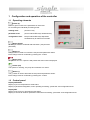
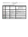
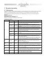
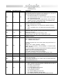
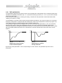
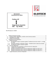
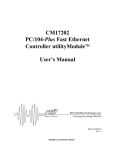
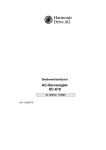
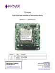
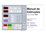
Operating Instructions SINGLE SBC – Controller SBC_EN_15_06 Contents Configuration and operation of the controller .................................................................................................. 2 1 1.1 Operating elements ................................................................................................................................. 2 1.2 Control panel ........................................................................................................................................... 2 1.3 Alarm panel and display information ....................................................................................................... 3 2 Parameter description ...................................................................................................................................... 4 2.1 Working level ........................................................................................................................................... 4 2.2 Parameter level ........................................................................................................................................ 6 2.3 Configuration level ................................................................................................................................... 7 2.4 Setting the control parameter ................................................................................................................10 2.4.1 Determining the parameters with closed control circuit .................................................................10 2.4.2 Self-optimisation ............................................................................................................................11 3 Connecting diagram .......................................................................................................................................12 4 Technical data ................................................................................................................................................12 1 Configuration and operation of the controller 1.1 Operating elements -button (P) Button P gives access to the parameters of each level. For accessing the individual processing levels: working level: push the P key parameter level: push P and ENTER keys simultaneously configuration level: keep P and ENTER keys depressed simultaneously for about four seconds - button (Enter) All changes must be confirmed with this button. (set-point and parameter) - button (+) The (+) button is used to increase the set-point and parameter values. Each change must be confirmed by pressing the ↵ button. - button (Off) All systems are “off”. If power is still present the start screen is displayed. - button (On) The system is “working”, the pump and controller are “active”. - button (–) The (-) button is used to decrease the set-point and parameter values. Each change must be confirmed by pressing the ↵ button. 1.2 Control panel Display PROCESS: Display of pre-run temperature's actual-value. Display of parameter designation, when operating at working-, parameter- and configuration-level. Display SET Display of the current or programmed set-values. Display of numerical values or parameter values when at working-, parameter- and configuration-level. 1.3 Alarm panel and display information Symbol Designation LED glows because: Rectification / explanation Water: with manual filling: replenish with heat transfer medium with automatic filling: open cooling water supply, wait till filled Oil: fill or replenish with oil Not up to temperature, or outside bandspread (limit) Band-spread too narrow or limiting value made. Turn OFF at working level, parameter AL, or set band-spread. Check set limiting value; insufficient heat dissipation by consumer. Subsequent to cooling by 5 K, heating comes ON again Minimum level Minimum level not made Limit-comparator Limit-comparator outside band-spread, limiting value exceeded Pre-run temperature Pre-run temperature up to limiting value Heating switches OFF Heating Heating on - Cooling Cooling on - Operating mode display Temperature control unit (TCU) activated LED flashes when the TCU is - switched off via the pump after-run control - too full in oil configuration 2 Parameter description 2.1 Working level Pushing the P-button, will access the working level. Individual parameters are accessed by pushing the button marked P. The PROCESS-display shows the parameter. The SET-display shows the parameter value. The first display shown after pressing button P is the status display. If an error has occurred, this will be displayed: ALAr FLO = flow error ALAr PUMP = motor contactor triggered ALAr FILL = filling time exceeded ALAr niv.H = max level. exceeded (only with oil units) Parameter description: Parameter Set-values range OFF OFF AL OFF, -99 100 MR*-start MR*-end OFF, 0 100 OFF, -99 100 MR-start MR-end OFF, 0 100 OFF, 0 100 Signifying Alarm outputs selected. Alarm output programmed as signal contact max. OFF-ON. The setting-value corresponds to the alarm’s response value, relative to the set point-value. Alarm output programmed as limiting contact max OFF-ON. The set point-value corresponds to the absolute response-value of the alarm. Alarm output programmed as limit comparator OFF-ON-OFF. The set point-value corresponds to the set point’s tolerance-value. Alarm output, programmed as signal contact max. ON-OFF. The setting-value corresponds to the alarm’s response value, relative to the set point-value. Alarm output programmed as limiting contact max ON-OFF. The set point-value corresponds to the absolute response-value of the alarm. Alarm output programmed as limit comparator ON-OFF-ON. The set point-value corresponds to the set point’s tolerance-value. Alarm output programmed as limit comparator ON-OFF-ON (with stand-by response). The set point-value corresponds to the set point’s tolerance-value. No alarm during initial start-up, until the input range is made. nd SP2 MR-start Set-value limiting AP.I MR-start MR-end Ati OFF=0 40 Cti OFF, 10 900 LS OFF on rEMo OFF *MR = metering range on Programmed value corresponds to 2 set-value. nd Change-over to 2 set-value takes place via parameter SET = SP.2 at working level. Also refer to configuration level. Programmed value corresponds to the response temperature of the inlet-temperature limitation. If up to end of measuring range is programmed, the value end of measuring range +5°C is displayed. Aquatimer: set point-value corresponds to the max. permissible filling cycles after 1 hour of operation. Change time; evacuation / vacuum time on units with automatic mold draining. Set point-value corresponds to the compressed-air assisted evacuation time or else the vacuum-time in seconds. Turning the leak-stop mode ON and OFF. ON means leak-stop mode turned ON. OFF means leak-stop mode turned OFF. Turning the remote function ON and OFF at units with interface. Parameter Set-values range niv Hand Auto CHG no.Ch Chg dir indi dir bLEd OFF, 1 240 C.OFF OFF Co.OF SEt SP.1 SP.2 Adr 1 255 AL2 t.out Signifying Hand = manual filling of the unit Auto = automatic filling of the unit Auto not possible for heat transfer units with oil no.Ch mould draining not active Chg mould draining active. Only for units with mould draining! Change-over must be set free in the configuration level! indi = Cooling via heat exchanger dir = direct Cooling Direct cooling only possible at units with water Change-over must be set free in the configuration level! Vent after switching on Setting in seconds OFF means, that the unit is turned OFF directly with the „0“ key. Co.OF means, that when pushing the "0" key, the unit is cooled down first, before it is turned OFF. (Pump lag control) Change-over SP.1 = internal set-value active SP.2 = second set-value active Input of unit addressing. If several units are operated by the same interface, different addresses must be chosen. Compare with parameter AL Shows the pre-run temperature in the SET-display 2.2 Parameter level Pushing the buttons P and ↵ will access the parameter level. Individual parameters are accessed by pushing the P-button. The PROCESS-display shows the parameter. The SET-display shows the parameter value. Parameter Y% hL% cL% hP hd hl cP cd cl Set-values range 0 0 OFF, 0.1 OFF, 1 OFF, 1 OFF, 0.1 OFF, 1 OFF, 1 100 100 99.9 200 999 99.9 200 999 db OFF, 0.1 10.0 hC cC 1 1 240 240 SP.Hi SP.Lo MR-end SP.Lo MR-start SP.Hi SCL OFF, 35 90 C-F C 0,1 C OPt OFF on SP/ SP\ HY.Hi HY.Lo h OFF_ 0,1 OFF_ 0,1 0,5 0,5 99,9 99,9 10,0 10,0 Signifying Indication of the actual limitation of regulation ratio 1 Limitation of regulation ratio for heating in % 1 Limitation of regulation ratio for cooling in % XP-Heating in %, the control system’s proportional range TV-Heating in sec., derivative action time of the control system TN-Heating in sec., integral action (reset) time of control system XP-Cooling in %, the control system’s proportional range TV-Cooling in sec., derivative action time of the control system TN-Cooling in sec., integral action (reset) time of control system Switching hysteresis between heating and cooling. This parameter is used for increasing the set-value (switching point) for cooling by the value entered. That way, possibly too frequently occurring switching changes between heating- and cooling modes can be prevented. Simultaneous switching of heating and cooling can be ruled out generally. Settings are in °C. 2 Heating switch-cycle time in sec. 2 Cooling switch-cycle time in sec. Upper set point limitation in °C. Here the final value for the set point setting range can be selected. Lower set point limit in °C. The start value of the set point adjustment range can be preselected here. System Closed = system shut-off on units employable at > 90°C, the water system is shut-off to atmosphere. Water: temperature selection for system shut-off in °C Oil: evacuation by vacuum only possible below the set SCL-value (CHANGE) Selection °C, °F or 1/10 °C Turning self-optimization ON and OFF. ON = Self-optimization started. The controller determines the optimum control parameters by closed-loop control. Also refer to Chapter 2.4 „Setting the closedloop control parameters”. Set point ramp rising Set point ramp decreasing Cooling ON hysteresis Cooling OFF hysteresis Operating hours 1 Limitation of the regulation ratio is only required with an excessively overdimensioned energy supply for the control system, or for turning-OFF the corresponding actuating output port (setting 0 %). It should be inoperative under normal circumstances (setting 100 %). Limitation of the regulation ratio becomes active, when the regulation ratio calculated by the controller is greater than the max. permissible (limited) regulation ratio. Please note: Limitation of regulation ratio is ineffective during the self-optimization phase. 2 The control element’s maximum switching frequency is determined with the assistance of the switch-cycle time. This is the period during which the controller carries out one ON and one OFF switching action. We recommend the following settings: − Relay-setting outputs with downstream installed contactors: switching cycle > 10 s − Bi-stable voltage output ports for actuating Solid State Relays (SSR): Switch-cycle time 1 ... 10 s − Continuous actuator output: Switch-cycle time 1 s 2.3 Configuration level Pushing the buttons P and ↵ for about four seconds will access the parameter level. Individual parameters are accessed by pushing the P-button. The PROCESS-display shows the parameter. The SET-display shows the parameter value. Parameter Set-values range LOC OFF ALL ECO OFF on niv on LOC c60 OFF, 10 100 C.OIL AqUA OIL cdi OFF on C.AL OFF 7 C.SA oP cL Signifying Keyboard interlock • OFF= parameter values can be changed. • PC = Parameter level and configuration level barred. Parameters can only be viewed. • SP.t = set point-value can be altered. All function keys are enabled, if not barred by the configuration level. • o.SP = all keys, except for „0“ and „I“ are barred; only the set point-value can be altered • ALL = complete keyboard interlocking; it is only possible to switch ON and OFF; no set point-value alteration possible! Please note! When changing the LOC-parameters, ENTER must be kept depressed, until the moving illumination has passed-through for the second time (about 5 s )! Configuration of external contact OFF: Pin 10 = inlet flow monitor on: Pin 10 = switch-over setpoint value 1 / setpoint value 2 Enabling the filling modes „AUTOMATIC/MANUAL“ • on = change-over facility of the key marked LEVEL is enabled • LOC = change-over facility of the key marked LEVEL is blocked. Enabling or locking the software-key of the pump-lag control • OFF = „OFF“-key blocked • 10...100 °C = adjustable switch-OFF temp. AQUA = water unit OIL = oil unit Interlocking of the “direct cooling” key (unit must be equipped with hydraulics) • on = change-over to direct cooling is enabled • OFF = no direct cooling allowed Configuration of the alarm output port • OFF = Alarm has been turned OFF • = Signal contact OFF-ON • = Limiting contact OFF-ON • = Limit comparator OFF-ON-OFF • = Signal contact ON-OFF • = Limiting contact ON-OFF • = Limit comparator ON-OFF-ON • = Limit comp. with stand-by response In the ON-position, output port is open. In OFF-position, output-port is closed. Configuration group interrupt • oP = n/c contact • cL = n/o contact Parameter Set-values range ChL dd Ldd E.LS on LOC ASt 5 min 120 FiLL OFF; 1 99 EMO OFF on OF1 OF4 OFF, -100 OFF, -100 100 100 OF6 OFF, 1 100 P.Fi OFF, 0,1 60 Pro OFF St Signifying Change-logic configuration The change sequence will have to be preselected as a function of the unit’s hydraulic and electrical specifications. • dd = Mold evacuation by compressed air • LS = Mold evacuation by vacuum suction (leak stop-function) • Ldd = at present as per dd • 8-9 = Mold evacuation with compressed air, when units with “System shut-off in cooling water return” are employed, e.g. STW 1-HTK and STW 150/1-HK + HN Interlocking of “LS” leak-stop parameter at working level (when hydraulic prerequisite is missing). • ON = Changing of the “LS”-parameter enabled at working level • LOC = Changing of the „LS“-parameter blocked at workinglevel Aquatimer-Start-time (min) Aquatimer (filling-impulse-counter) becomes active following the time set in the "ASt". Previously not monitored random filling cycles. Renewed start of the "AST" time, following the On/Off. Monitoring of filling time Setting in minutes Restart lockout after power reset off = Restart lockout not active on = Restart lockout active Following a power reset, the control system stays turned OFF, to start with. Display "Info". "EMO" message – flashing. LED in the "O"-key flashes. All other displays – except for Power LED – are OFF. The control system can be turned ON with the following sequence. ENTER the "EMO"-message with the "O"-key. LED in "O"-key is now permanently alight. The “EMO”-message must then be deleted. Now the control system can be turned ON with the “I”-key. Temperature correction of the internal temperature probe in °C Temperature correction of the probe for inlet temperature in °C Duty cycle offset info for system output cooling. Use of the parameter: To equalize unsteadiness of a cooling valve, an offset (OFF-Set) can be entered here in %. Filter for stabilization of the actual-value display Setting of the various interface protocols • OFF = interface mode turned OFF. Parameter Adr, b and For are without any significance • A = Arburg-protocol active • A = Krauss Maffei-protocol active • b = Dr. Boy-protocol active • E = Engel-protocol active • CП = Krauss Maffei-protocol active • St = SINGLE Standard-protocol active • Pb = Profibus active only at SBC with Profibus interface Parameter b Set-values range OFF, 0.3 19.2 For 7E1 8n2 dn1 dn2 C.OFF 0 0 c.OFF 999 999 c.Gr C.A2 ConF 3P 2PC PSI Signifying This is where the transmission speed – baud rate – of the interface is being programmed. Possible settings are as follows: • OFF = no baud rate set • 0.3 = 0.3 kBaud • 0.6 = 0.6 kBaud • 1.2 = 1.2 kBaud • 2.4 = 2.4 kBaud • 4.8 = 4.8 kBaud • 9.6 = 9.6 kBaud • 19.2 = 19.2 kBaud Here the Interface’s data format is being programmed. The data-format is comprised of: Data-bits, parity bit, stop bit. Possible settings are: 7E1, 7o1, 7E2, 7o2, 7n2, 8E1, 8o1, 8n1, 8n2 Here the first 3 digits of the equipment No. are programmed. Here the last 3 digits of the equipment No. are programmed. Programming c.OFF After switch-off via the pump run-on control, 100% cooling is effective until cooling temperature is reached. Programming c.Gr After switch-off via the pump run-on control, the default cooling gradient is effective until the cooling temperature is reached. Compare with parameter C.AL Control response configuration 3P 3-point controller heating/cooling 2PC 2-point controller cooling - 2.4 Setting the control parameter 2.4.1 Determining the parameters with closed control circuit If the time response of the controlled system is unknown and if the control circuit can be made instable for short periods, then the controller is operated with xp = 0 (on-off, without time response). The control parameters are calculated from the resulting waveform as follows: X (°C) Δx t (sec.) T Δx = oscillation period = oscillation amplitude of the actual value Delay time: Lead time: Reset time: Proportional range: Span SC: 1 ∗T 4 4 Tv = ∗ Tu 10 Tn = 5 ∗ Tv ∆x ∗ 2 xp = ∗ 100% Meßbereichsumfang 430 K Tu = We recommend setting the proportional range “cooling“ to two times the value. Self-optimisation 2.4.2 The optimisation algorithm with closed control circuit ascertains the characteristics of the controlled system and calculates the feedback parameters (Xp, Tv, Tn) and the switching cycle time (C = 0.3 x Tv) for a PD/I controller valid over a wide range. If the controller is operated as a “heating-off-cooling” controller then the parameter values determined under “heating” are used for “cooling”. The optimisation is carried out during start-up shortly before the setpoint. This must be at least 5 % of the span. During the optimisation to a setpoint that has already been reached, the temperature is reduced by approx. 5% of the span in order to accurately determine the controlled system gain. The optimisation algorithm can be triggered at any time by selecting “Self-optimisation = ON” and confirming with the “Enter” button. During the optimisation process “Opt. Activ” is shown in the display. With 3-point controllers (heating-off-cooling) the temperature reduction is accelerated via short-term activation of the cooling. After the feedback parameters have been calculated the controller maintains the actual value at the current setpoint. X w X w OPT on t Optimisation during heating of the controlled system y OPT on t Optimisation to setpoint already "attained” y By selecting “Self-optimisation = OFF” and pressing the “Enter” button, the optimisation process can be interrupted. 3 Connecting diagram Interface optional! 0/20 mA TTY St3 PIN Profibus DP GND RxTxP RxTxN Vp +5V TTY 20 mATTY 20 mA+ draining system closing pump heating motor protection level min. Pt 100 control 0V 85 86 87 88 St1 PIN 17 18 15 16 13 14 11 12 9 10 7 8 5 6 3 4 1 2 leak-stop pilot contact heating filling cooling flow watchdog level max. Pt 100 temperature monitoring 24 V St2 PIN 3 2 1 group alarm normally open contact opener two-way contact 4 Technical data Power supply 24V DC 0,1A Actual value monitoring Pt 100 2-two-wire lead Resolution 0,1°K Data sampling 0,1s Measuring range -30…400°C Sensor break and short circuit monitoring are present Sensor voltage ≤ 1mA Calibration accuracy ≤ 0,2% Linearity and indication error ≤ 0,2% +/-1digit Ambient temperature influence on the span ≤ 0,02% / K Inputs Switching voltage 24V DC Input current 1mA Suitable for the connection of external, floating contacts Outputs 24V DC 0,5A 2A max. SMD fuse 4A Short circuit proof, suitable for inductive loads Relay 1 two-way contact 250V AC 3A cos phi 1