1
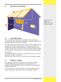
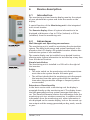
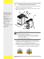
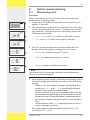
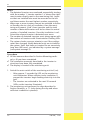
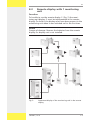
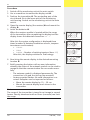
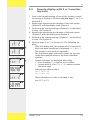
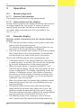
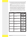
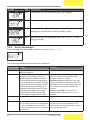
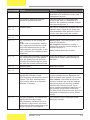
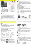
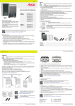
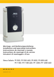
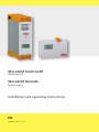
StecaGrid Control N1 Monitoring Unit StecaGrid Remote Remote Display Installation and operating instructions EN 746.490 | Z01 | 12.41 EN Contents General safety instructions 3 System overview 4 Introduction4 Proper usage 4 About these operating instructions 5 Contents5 Target group 5 Symbols and markings 6 Device description 7 Introduction7 Advantages7 Mounting method 8 Installing the monitoring unit 9 Wiring the AC plug 10 Initial commissioning 11 Monitoring unit 11 Remote display with 1 monitoring unit 13 Remote display with 2 or 3 monitoring units 15 Operation16 Monitoring unit 16 Remote display 16 System expansion 19 Expansion of an existing monitoring unit with a remote display 19 Replacing a monitoring unit 19 Expanding from 2 to 3 monitoring units 19 Technical data 20 StecaGrid Control N1 20 StecaGrid Remote 20 AC cables and line circuit breakers 20 Correction of faults 21 Display messages 21 System messages 21 Error messages 22 Maintenance24 Disposal24 Exclusion of liability 24 Commercial and legal guarantee conditions 25 Contact26 Notes26 2 746.490 | 12.41 EN 1 General safety instructions Warning Risk of death by electrocution! The unit may only be connected to the grid by qualified personnel in accordance with the regulations of the local power authority. • This document is part of the product. • Use the device only after reading and understanding this document. • Keep this document in a safe place for the entire service life of the device. Pass this document on to subsequent owners and operators of the device. • Improper operation can reduce the yields of the solar system. • The device must not be connected to the AC power lines if it has an open or damaged casing. • If one of the following components is damaged immediately take the device out of operation and disconnect it from the mains grid and modules. – The device (not functioning, visible damage, smoke, etc.) – Cables – Modules The system must not be switched on again until: – The device has been repaired by a dealer or the manufacturer. – Damaged cables or modules have been repaired by a technical specialist. • Observe the prescribed conditions of use, see Section 11, p. 20. • The permitted ambient conditions at the installation site – in particular, the specified protection class – must not be exceeded. • Ventilation openings must never be covered or closed. • Factory labels and markings must never be altered, removed or rendered unreadable. 746.490 | 12.41 3 EN 2 System overview Solar modules Inverter Monitoring unit Remote display 3 Introduction This document contains the installation and operating instructions for the StecaGrid Control N1 monitoring units and the StecaGrid Remote remote display. The Steca grid-connected system is easy to put together from a range of matching components. The system consists of MiniString inverters and monitoring / remote displays. The system is technically state-of-the-art, environmentally friendly and functional. It is also easy to install and can be expanded as required. See www.stecasolar.com for current information on our comprehensive range of products. We wish you every success in installing and using the system. 4 Proper usage The optional StecaGrid Control N1 monitoring unit and StecaGrid Remote remote display may only be used with StecaGrid 300/500 inverters and within the permitted ambient conditions. The total power of StecaGrid 300 or StecaGrid 500 connected to a StecaGrid Control N1 must not exceed 3.600 W. 4 746.490 | 12.41 EN 5 About these operating instructions 5.1 Contents These instructions contain all the necessary information for installing and operating the StecaGrid Control N1 monitoring unit and the StecaGrid Remote remote display. Consult the following documents for information on installing other components: • The Steca instructions for the StecaGrid 300/500 inverters • Instructions from the respective manufacturers of the remaining components such as photovoltaic modules, DC and AC cabling and other accessory devices 5.2 Target group The target audience of this manual are technical professionals who: • have the knowledge of terminology and the skills necessary for setting up and operating photovoltaic systems. • have the necessary training, knowledge and experience, and knowledge of the applicable regulations in order to evaluate and recognise the dangers inherent in the following work: – Installation of electrical equipment – Production and connection of mains grid power supply cables End customers are only permitted to perform normal operating functions; see Section Operation, p. 16. 746.490 | 12.41 5 EN 5.3 Symbols and markings This document contains the following symbols and markings: 5.3.1 Warning and operating notes Warning and operating notes commence with a combination of a symbol and a keyword, followed by the explanation. Symbols Symbol Description General danger warning Location Manual Danger from electricity Manual Keywords Danger immediate danger of death or serious bodily injury Warning possible danger of death or serious bodily injury Caution possible danger of light or medium bodily injury Notice possible damage to property Example: Warning Risk of death by electrocution! • When working on the photovoltaic system, disconnect the inverter from the power supply. • Make sure that the power supply cannot be unintentionally switched on. 5.3.2 Labels used in the text Label Description 1., 2., 3. ... ✔ Single step Several steps in sequence Condition for action italics Emphasis, light bold Emphasis, heavy italic underlined Cross-reference Courier Designation of product elements such as buttons, displays, operating states 6 746.490 | 12.41 EN 6 Device description 6.1 Introduction The monitoring unit and remote display monitor the output of your photovoltaic system and show the results on the display. A special function of the Monitoring unit is the integrated main circuit breaker The Remote display allows all system information to be displayed at distances of up to 100 m (indoors) or 300 m (outdoors) from the monitoring unit. 6.2 StecaGrid Control N1 monitoring unit Remote display StecaGrid Remote Advantages Well thought-out operating convenience The monitoring unit is used for monitoring the photovoltaic system. The data (total energy and system messages) is displayed on the LCD display. An optional wireless remote data transmission system is also available. The remote display can be installed in any desired location, allowing extra system information to be called up at any time from the desired location. Simple installation The monitoring unit is installed in a DIN rail to the right of the inverters. Safety • The main switch on the monitoring unit disconnects/connects the entire system from/to the mains grid. • The self-test checks that the monitoring unit disconnects the inverters from the mains grid within the specified time when the permissible voltage or frequency values are exceeded. Extension of functionality In the basic version with a monitoring unit the display is mounted directly on the monitoring unit. The display shows the kWh generated and any system messages that may occur. The StecaGrid Remote receives the information from the monitoring unit via a wireless connection. In addition to the information from the monitoring unit, other information is also displayed on the remote display, such as the current system output and the energy generated per day, week, month or year. 746.490 | 12.41 7 EN 7 Mounting method Danger Risk of death by electrocution! Always observe the following safety measures when working on the photovoltaic system. • The monitoring unit may only be connected to the grid by qualified personnel in accordance with the regulations of the local power authority. • When working on the photovoltaic system, disconnect the inverter or monitoring unit from the power supply via the circuit breaker. • Make sure that the power supply cannot be unintentionally switched back on. • Lay the cable such that the connection cannot come loose accidentally. • The inverter and monitoring unit must not be opened. Only the remote display unit may be opened to insert the display and the batteries. 8 Warning Do not install either unit • outdoors, • in damp rooms, • In rooms which are too hot, • In dusty rooms, • in rooms where highly flammable gas mixtures can occur. Observe the protection class of the devices; see Section 11, p. 20. 746.490 | 12.41 EN 7.1 Installing the monitoring unit ✔✔ One or more StecaGrid 300/500 inverters are mounted on DIN rails; see the inverter instructions. ✔✔ Space for a monitoring unit exists on the DIN rails to the right of the inverters. – + StecaGrid 300/500 DC voltage inputs (solar module connections) AC voltage output AC connection DIN rail AC voltage output for grid feeding StecaGrid Control N1 monitoring unit Data connection LED Self Test button (no function in StecaGrid Control N1) Main switch / Fig. 1: Installing the monitoring unit Danger Risk of death by electrocution! • Always observe the safety measures described in Section Mounting method, p. 8 when working on the solar system. • Do not touch bare cable ends. 1. Insert the AC connection and data connection on the right side of the rightmost inverter. (Connection is supplied with the StecaGrid 300/500 inverters.) 2. Fasten the monitoring unit to the DIN rails as follows: a. Slide the monitoring unit fastening clip (at the lower rear) downwards, as shown in the adjacent figure. 1 746.490 | 12.41 2 9 EN b. Hook the monitoring unit first onto the upper rail and then onto the lower rail. c. Slide the monitoring unit towards the left as far as it will go until it lies adjacent to the (rightmost mounted) inverter . The AC connection and data connection must latch into place on both units. d. Slide the fastening clip upwards once more The monitoring unit is now mounted. 7.2 Wiring the AC plug The grid feed cable is connected via the AC plug to the grid feed AC output connection ( in Fig. 1). The AC plug is supplied with the unit. Information on the pin assignments us provided on the plug. 10 746.490 | 12.41 EN OFF STANDBY ACTIVE W/ m2 kWh C IRRAD TEMP POWER OFF STANDBY ENERGY /D /W /M /Y ACTIVE W/ m2 kWh C IRRAD TEMP POWER OFF STANDBY ENERGY /D /W /M /Y 8 Initial commissioning 8.1 Monitoring unit Function When switched on for the first time, the monitoring unit performs the following steps: 1. Display test: All symbols illuminate at the same time for approx. 2 seconds. 2. The monitoring unit detects the units that are connected to the system (irradiation sensors1), temperature sensors1) and inverters). During the process the display shows the following information: – init, IRRAD and TEMP while searching for sensors – init and POWER while searching for inverters ACTIVE W/ m2 kWh C IRRAD TEMP POWER OFF STANDBY ENERGY /D /W /M /Y ACTIVE W/ m2 kWh C IRRAD TEMP POWER OFF STANDBY ENERGY /D /W /M /Y 3. Once all system components have been detected, the display shows the system configuration in 3 steps: – IRRAD: no irradiation sensors1) found – TEMP: no temperature sensors1) found ACTIVE W/ m2 kWh C IRRAD TEMP POWER OFF STANDBY ENERGY /D /W /M /Y – POWER: number of detected inverters ACTIVE W/ m2 kWh C IRRAD TEMP POWER ENERGY /D /W /M /Y 1) Note The possibility of connecting irradiation and temperature sensors is not implemented. 4. After displaying the system information the display shows the Total energy generated by the system. The following applies: – When one or more system messages are displayed alternately (e.g. Err 1 and 01.40), then the grid voltage of inverter 01 lies outside the specified range. At this point this is not an error because 230 V was not present when the monitoring unit was switched on ans the inverter must wait 20 seconds before it can become active. – The system messages disappear after a short period of time. – An exclamation mark „!“ is displayed when at least 1 system message is present. More information on this is provided in Section 8.2, p. 13 and Section 12.1, p. 21. 746.490 | 12.41 11 EN Notes • The detected inverters are numbered sequentially starting with the number 1. Inverter number 1 is always the rightmost inverter directly next to the monitoring unit. Inverters that are installed later must be mounted to the left and these receive the next highest number respectively. • When one or more inverters cannot be switched to Active or Standby due to a lack of irradiation, then the monitoring unit cannot „find“ these inverters and the total number of detected inverters will be less than the actual number of installed inverters. Once the irradiation is sufficient the relevant inverter is detected once more. • The number of detected inverters must always agree with the number of inverters with illuminated or flashing LEDs. • The system checks once per minute to see if the configuration has changed. Newly detected units are included in the system. Units that have not reacted for an excessively long time (48 hours), are indicated by a system message (see system message 2). Procedure ✔✔ All the measures described in Section Mounting method, p. 8 have been completed. ✔✔ The installation measures described in the inverter instructions have been fully completed. ✔✔ The display is located in the monitoring unit. 1. Switch the main switch of the monitoring unit to I (on). – After approx. 5 seconds the LED on the monitoring unit illuminates. When sufficient solar irradiation is present the inverters begin feeding electricity into the grid´. – The inverters are activated in the next 20 seconds (LEDs on the inverters illuminate). 2. The monitoring unit performs the steps described in Section Function, p. 11 (only during the day and when sufficient irradiation is present). 12 746.490 | 12.41 EN 8.2 Remote display with 1 monitoring unit Function To be able to use the remote display (Fig. 2) the monitoring unit display must be implemented in the remote display. To do this, the display must have been present in the monitoring unit when it was switched on for the first time. Notice Danger of damage. Remove the batteries from the remote display if a display unit is not installed. Fig. 2: Implement display of the monitoring unit in the remote display 746.490 | 12.41 13 EN Procedure 1. Switch off the monitoring unit at the main switch. 2. Use a screwdriver to remove the display unit . 3. Position the transmitter . The protruding part of the circuit board fits in the lower part of the monitoring unit housing. Switch on the monitoring unit at the main switch. 4. Open the remote display (the receiver) and mount the display . 5. Insert the batteries . When the receiver module is located within the range of the transmitter, after completing the display test the display shows the detected connection: rF 1. After this the system configuration is displayed three times (number of detected irradiation sensors, temperature sensors and inverters): • IRRAD • TEMP • POWER – Number of existing inverters (here: 02) After this, the display switches to Total energy. OFF Note The range of the transmitter is tuned to suit usage in normal homes. Heavily absorbent walls or floors (concrete) can limit the range. 14 746.490 | 12.41 ACTIVE W/ m2 kWh C IRRAD TEMP POWER OFF STANDBY ENERGY /D /W /M /Y ACTIVE W/ m2 kWh C IRRAD TEMP POWER OFF STANDBY ENERGY /D /W /M /Y ACTIVE W/ m2 kWh C IRRAD TEMP POWER OFF 6. Now bring the remote display to the desired mounting location . 7. Briefly pressing the button calls up new information, whereby the status of the antenna symbol can be used to recognise that the communication has occurred successfully. – The antenna symbol is displayed permanently: The connection is ok and the unit can be mounted. – Antenna symbol flashes: No valid information is received. Reception can be improved as follows: • Move the remote display by 10 ... 20 cm. • Mount the remote display much closer to the transmitter. STANDBY STANDBY ENERGY /D /W /M /Y ACTIVE W/ m2 kWh C IRRAD TEMP POWER ENERGY /D /W /M /Y EN 8.3 OFF STANDBY ACTIVE W/ m2 kWh C IRRAD TEMP POWER OFF STANDBY ENERGY /D /W /M /Y ACTIVE W/ m2 kWh C IRRAD TEMP POWER OFF STANDBY ENERGY /D /W /M /Y ACTIVE W/ m2 kWh C IRRAD TEMP POWER OFF STANDBY ENERGY /D /W /M /Y ACTIVE W/ m2 kWh C IRRAD TEMP POWER OFF STANDBY ENERGY /D /W /M /Y ACTIVE W/ m2 kWh C IRRAD TEMP POWER OFF STANDBY ENERGY /D /W /M /Y Remote display with 2 or 3 monitoring units 1. Start initial commissioning of one of the systems, hereafter known as System A. Perform only the steps 1. to 3. in Section 8.2. 2. Replace the monitoring unit display of the next system (System B) with the display from System A. 3. Perform initial commissioning of System B, as described in step 1 for System A. 4. Replace the monitoring unit display of the next system (System C) with the display from System B. 5. Perform initial commissioning of System C, as described in step 1 for System A. 6. Perform steps 4. to 7. in Section 8.2. The following applies: – After the display test, the number of HF connections that have been established is displayed: rF 2 or rF 3. The system is now ready for operation. – The specified output and power values are now the respective summed values of the three individual systems. – System messages are displayed alternately: • Error message: Err and the error number • System letter A, B or C (A, b, C), inverter number and error code Example (see adjacent Fig.): Err 1 / A02.40 Err 2 / b01.44 More information on this is provided in Section 12.1, p. 21. ACTIVE W/ m2 kWh C IRRAD TEMP POWER ENERGY /D /W /M /Y 746.490 | 12.41 15 EN 9 Operation 9.1 Monitoring unit 9.1.1 General information The monitoring unit functions fully automatically. 9.1.2 Information on the display During normal operation the display shows the total amount of energy supplied by the system. In certain situations, special system messages are shown on the display (error codes). More information on this is provided in Section 12.1, p. 21. 9.2 Remote display Read the system information from the remote display as follows: 1. Press the menu button briefly to call up the current information from the monitoring unit. The antenna symbol disappears briefly and then the current value of the first parameter is displayed. 2. Press the menu button again within 10 seconds to display the current value of the next parameter. The parameters are described in the table at the end of this section. Observe the following points when operating the unit: • If the menu button is not pressed then new information is called up every 1o minutes. This can also be recognised by the brief disappearance of the antenna symbol. • When the menu button is pressed and held for 5 seconds the remote display calls up new information via the system configuration. The display sequentially shows the number of irradiation sensors, the number of temperature sensors and the number of inverters (inverters that are nor active or are in Standby, e.g. due to inadequate irradiation, are not included). • When the system does not contain any irradiation and/or temperature sensors then the corresponding menu settings are skipped. • The battery symbol flashes when the battery voltage drops below the nominal value. When this occurs, the batteries should be replaced within the next 3 months. After the batteries have been replaced, the remote display must be restarted as described in Section 8, p. 11. • The kWh/day meter starts running as soon as the system is operational. The weekly and monthly meters are 16 746.490 | 12.41 EN incremented each evening by the total energy generated on the respective day. The year meter is incremented once a week by the total energy generated in the respective week. • When the respective period expires, e.g. 7 days for the week, 30 days for the month and 52 weeks for the year, the relevant old information is deleted so that the running totals are always correct for each respective period. • Since the annual total is not updated until the end of a week and the weekly and monthly totals re updated at the end of each day, the value displayed for the annual total may initially be smaller than the weekly or monthly total. Parameter Description Switching on All segments are visible for 2 seconds. Display segments OFF STANDBY ACTIVE W/ m2 kWh C IRRAD TEMP POWER Energy since installation Total energy in kWh since commissioning OFF STANDBY ENERGY /D /W /M /Y ACTIVE W/ m2 kWh C IRRAD TEMP POWER Current system output Current AC power of the system. OFF STANDBY ENERGY /D /W /M /Y ACTIVE W/ m2 kWh C IRRAD TEMP POWER Energy per day Total energy generated today (from 00:00h) to the current time. OFF STANDBY Total energy generated over the last 7 days. /D /W /M /Y ACTIVE W/ m2 kWh C IRRAD TEMP POWER Energy per week ENERGY OFF STANDBY ENERGY /D /W /M /Y ACTIVE W/ m2 kWh C IRRAD TEMP POWER Energy per month Total energy generated over the last 30 days. OFF STANDBY ENERGY /D /W /M /Y ACTIVE W/ m2 kWh C IRRAD TEMP POWER Energy per year Total energy generated over the last 52 weeks. OFF STANDBY ENERGY /D /W /M /Y ACTIVE W/ m2 kWh C IRRAD TEMP POWER 746.490 | 12.41 ENERGY /D /W /M /Y 17 EN Parameter Description Display segments At the same time as the parameters above, the following operating states are also displayed: Active At least one inverter is feeding OFF STANDBY ACTIVE energy into the grid. W/ m2 kWh C IRRAD TEMP POWER Standby At least one inverter is in Standby and no inverter is active. OFF STANDBY No inverter is active or in Standby. /D /W /M /Y ACTIVE W/ m2 kWh C IRRAD TEMP POWER Off ENERGY OFF STANDBY ENERGY /D /W /M /Y ACTIVE W/ m2 kWh C IRRAD TEMP POWER ENERGY /D /W /M /Y Additional display messages: Battery HF transmission When the battery symbol in the display flashes then the battery must be replaced soon. When the antenna symbol is visible then the data communication is ok. OFF STANDBY ACTIVE W/ m2 kWh C IRRAD TEMP POWER OFF STANDBY /D /W /M /Y ACTIVE W/ m2 kWh C IRRAD TEMP POWER 18 ENERGY ENERGY /D /W /M /Y 746.490 | 12.41 EN 10 System expansion One of the advantages of the Steca inverter system is that it can be expanded at any time. This is described below. 10.1 Expansion of an existing monitoring unit with a remote display To expand the system with a remote display, follow the instructions below depending on the number of existing monitoring units: Number of monitoring units 1 Monitoring unit 2 or 3 monitoring units Instructions Section 8.2, p. 13 and Section 9.2, p. 16. Section 8.3, p. 15 and Section 9.2, p. 16. When expanding, the following applies: • The information on the total amount of kWh generated is retained and is included in the calculation of total values. • The information on kWh/periods is reset at the time the remote display is installed. 10.2 Replacing a monitoring unit When replacing an existing monitoring unit, proceed as described in Section 8.3, p. 15. 10.3 Expanding from 2 to 3 monitoring units To expand a system with 2 monitoring units to a system with 3 monitoring units, proceed as follows: 1. Mount the display unit of the remote display on the new (third) monitoring unit. 2. Continue as described in Section 8.3, p. 15. 746.490 | 12.41 19 EN 11 Technical data 11.1 StecaGrid Control N1 Input side 230 V AC AC connection (Wieland Electric GST 18i3V 1P1) 1) Data Steca data connection 1) Output side 230 V AC AC contact plug (Wieland Electric GST 18i3V); Mating plug included in delivery. Main switch Yes Display Yes Dimensions (H x D x W) 250 x 175 x 70 mm Weight 1.75 kg Own consumption 2.7 W Standards and certification marks EMC: Emission EN 50081-1 (EN 55014 and EN 55022) Interference immunity EN 50082-1 Safety EN 60950 Degree of protection IP 20 Grid monitoring none Certification mark CE mark 1) Both connection plugs are supplied with the inverter. 11.2 StecaGrid Remote Display of StecaGrid Control N1 Transceiver 868 MHz ISM Power supply 2x LR06 (AA) Range approx. 100 m indoors approx. 300 m outdoors Dimensions (H x D x W) 140 x 103 x 35 mm Weight 0.23 kg Standards and certification marks HF transmission EN 300 220 Degree of protection IP 20 11.3 AC cables and line circuit breakers AC cable conductor cross-section Line circuit breaker 1,5 mm2 B16 2,5 mm2 B16 or B25 20 746.490 | 12.41 12 Correction of faults 12.1 Display messages During installation and operation, situations deviating from normal behaviour may occur. These deviations are indicated by an error code on the display The following applies to the error codes: • Most error codes are only for informational purposes and can be explained by the current situation (see Section 12.2). Example: Error code 40 occurs when the system is not connected to the grid. • Other error codes indicate possible incorrect operation of the unit during installation or initial commissioning. • Very few error codes indicate a problem that needs to be corrected by the installer (see Section 12.3). The error codes and corrective measures to be taken are listed below. Notes During periods with little solar irradiation (e.g. mornings or evenings) messages regarding the switching on and off of inverters may be displayed. This is normal and these messages then disappear automatically. 12.2 System messages System messages appear automatically on the display, regardless of whether this is located on a monitoring unit or a remote display unit. The following applies: • System messages are displayed together with the currently set parameter values in an alternating sequence. • If several system messages are present then these are displayed sequentially. • An exclamation mark „!“ is shown on the display while a system message is active. • System messages are displayed together with the number of the inverter where the message comes from. The following table describes the different types of system message. Display OFF STANDBY ACTIVE Type Data Description Information on the set parameter, e. g. Total energy Err 1 System message 1 W/ m2 kWh C IRRAD TEMP POWER OFF STANDBY ENERGY /D /W /M /Y ACTIVE W/ m2 kWh C IRRAD TEMP POWER OFF STANDBY ENERGY /D /W /M /Y ACTIVE W/ m2 kWh 01.40 Inverter 01 signals error code 40: The grid voltage lies outside the normal working range. C IRRAD TEMP POWER ENERGY /D /W /M /Y 746.490 | 12.41 21 Display OFF STANDBY ACTIVE Type Data Description Information on the set parameter, e. g. Output Err 2 System message 2 W/ m2 kWh C IRRAD TEMP POWER OFF STANDBY ENERGY /D /W /M /Y ACTIVE W/ m2 kWh C IRRAD TEMP POWER OFF STANDBY ENERGY /D /W /M /Y ACTIVE W/ m2 kWh 02.40 Inverter 02 from System A signals error code 40: The grid voltage lies outside the normal working range. C IRRAD TEMP POWER OFF STANDBY ENERGY /D /W /M /Y Data ACTIVE W/ m2 kWh Information on the set parameter, e. g. ENERGY /W (energy per week) C IRRAD TEMP POWER ENERGY /D /W /M /Y 12.3 Error messages Error messages are displayed as follows (in this case: Err 1): OFF STANDBY ACTIVE W/ m2 kWh C IRRAD TEMP POWER ENERGY /D /W /M /Y The following table describes the error messages. Error message Cause Err 1 Err 2 Open circuit or defect in the required hardware. Open circuit or defect in the existing hardware. The inverters switch off when insufficient irradiation is present. The monitoring unit then regards these as no longer present. However, these will become active on the next day and will be detected by the monitoring unit as properly functioning inverters. If a previously detected inverter can no longer be detected after 48 hours, then the monitoring unit regards this as a fault. Err 3 – Err Internal defect 8 Too many inverters are connected. Err 9 Remedy Notify the installer. No error: The error message disappears after the system has been manually switched off and on again. Hardware defect: When the error message is permanently displayed then this indicates an error in the Monitoring unit the cabling or an inverter. Notify the installer. Inverter removed: If an inverter is removed then replace this as soon as possible. Notify the installer. Limit the number of interconnected If too many inverters are connected inverters per row to a maximum of 5. to the communications bus then Connect the remaining inverters to their correct functioning can no longer be own monitoring unit. 1) guaranteed. 22 746.490 | 12.41 Error message Cause Remedy Err 10 More than 4 sensors are connected. Err 11 The total AC power exceeds the maximum permissible value. Err 12 – Err 16 Internal fault Err 17 – Err 24 Err 25 — Err 26 Err 27 Err 28 – Err 39 Err 40 Err 41 No connection to the remote display. In the case of atmospheric interference and poor transmission conditions the communication can be interrupted for brief periods. In this case, wait until the conditions have improved. The display has not been configured for a monitoring unit. This means that the display has not yet been installed in a monitoring unit while the unit was initially commissioned. Internal fault Limit the number of sensors to a maximum of 2 irradiation sensors and 2 temperature sensors. Limit the number of interconnected inverters per row to a maximum of 5. Connect the remaining inverters to their own monitoring unit. 1) This can be a temporary problem with an external cause. Check to see if the message disappears after 48 hours. If this is not the case then notify the installer. Not used. Battery fault: Check the batteries; try a new set of batteries. No reception: Attempt to achieve a connection with the remote display in a different position. 2) Other errors: Notify the installer. Install the display in a monitoring unit and perform initial commissioning on this unit 3). Notify the installer. Not used The grid voltage lies outside the permissible tolerance range. Grid frequency variations are rare In Europe. The error message therefore usually relates to a complete absence of voltage. The grid frequency lies outside the permissible tolerance range. Grid frequency variations are rare In Europe. If this occurs, the most likely cause is that connection to the electricity plant is interrupted. 746.490 | 12.41 No error: When switching on the inverter, this message may be displayed and then disappear after approx. 10 seconds. Poor contact: Check that all plug connections between the inverters and the monitoring unit are correctly installed and their pin contacts are ok. The inverter number provides an indication of the location of the faulty connection. The LED of the affected inverter does not illuminate constantly but rather flashes briefly. If an external cause cannot be found: Notify the installer. 23 Error message Cause Remedy Err 42 Grid synchronisation is not possible. Err 43 Err 44 Internal defect Notify the installer if this error message persists. Notify the installer. Insufficient power for switching to active. This message disappears under strong solar irradiation. 1) 2) 3) See also Section 8.3, p. 15. See also Section 8.2, p. 13. See also Section 8.1. 13 Maintenance The devices require no special maintenance. 14 Disposal The devices have a very long service life are are constructed from recyclable materials. XX At the end of it‘s life cycle, the product must be disposed of in accordance with the applicable regulations and recycling possibilities. XX 2 LR06 (or AA) batteries are used for providing power to the remote display. When exhausted, these batteries are to be disposed of as special waste. 15 Exclusion of liability The manufacturer can neither monitor compliance with this manual nor the conditions and methods during the installation, operation, usage and maintenance of the inverter. Improper installation of the system may result in damage to property and, as a result, to bodily injury. Therefore, we assume no responsibility or liability for loss, damage or costs which result from, or are in any way related to, incorrect installation, improper operation, or incorrect use and maintenance. Similarly, we assume no responsibility for patent right or other right infringements of third parties caused by usage of this inverter. The manufacturer reserves the right to make changes to the product, technical data or installation and operating instructions without prior notice. 24 746.490 | 12.41 16 Commercial and legal guarantee conditions Guarantee conditions for products from Steca Elektronik GmbH: 1. Defects in materials and workmanship The guarantee only applies to defects in materials and workmanship, insofar as these can be attributed to inadequate professional ability on the part of Steca. Steca reserves the right at its own discretion to repair, adapt or replace the faulty products. 2. General information In accordance with statutory regulations, there is a 2-year legal guarantee on all products for the customer. For this Steca product, we provide a voluntary 5-year commercial guarantee to the specialist dealer from the date of invoice or receipt. The commercial guarantee applies to products purchased and operated in EU countries or Switzerland. The commercial guarantee is also available in some countries outside the EU and this can also be extended. (Ask Steca about the commercial guarantee available in your country.) The legal guarantee entitlements are not restricted by the voluntary guarantee. To be able to make a claim under the guarantee the customer must provide proof of purchase (payment receipt). If a problem arises, the customer must contact his or her installer or Steca Elektronik GmbH. 3. Guarantee exclusion clause The guarantees on products from Steca Elektronik GmbH described under point 1 are not valid in the event that the fault is attributable to: (1) specifications, designs, accessories, or components added to the product by the customer or at the wish of the customer, or special instructions from the customer relating to the production of the product, the connection (of parts) of Steca products with other products that are not explicitly approved by Steca Elektronik GmbH; (2) modifications or adjustments to the product by the customer, or other causes due to the customer; (3) incorrect arrangement or installation, incorrect or careless handling, accident, transport, overvoltage, storage or damage caused by the customer or other third party; (4) unavoidable accident, fire, explosion, construction or new construction of any kind in the environment where the product is located, due to natural phenomena such as earthquakes, flooding, or storms, or any other cause outside the control of Steca Elektronik GmbH; (5) any other cause that could not be foreseen or avoided with the technology used in manufacturing the product; (6) if the serial number and/or the type number has been manipulated or rendered unreadable; (7) the use of the solar products in a movable object, for example ships, mobile homes, or others; (8) failure to conform to the instructions on care and maintenance of the product, as recommended by Steca in the operating instructions; (9) damage, soiling or painting of the casing so that cleaning or repair is no longer possible. The warranty stated in these operating instructions only applies to consumers who are customers of Steca Elektronik GmbH or of resellers authorised by Steca Elektronik GmbH. The guarantee mentioned here is not transferable to a third party. The customer shall not transfer his rights or responsibilities resulting from this in any way, without the prior written approval of Steca Elektronik GmbH. Furthermore, Steca Elektronik GmbH shall in no case be liable for indirect damage or loss of profit. Unless otherwise specified by any applicable compulsory legislative regulations, Steca Elektronik GmbH shall also not be liable for any other damages other than those for which Steca Elektronik GmbH has hereby explicitly accepted liability. 746.490 | 12.41 25 EN 17 Contact In the case of complaints or faults, we request that you contact the local supplier from whom you purchased the product. They will help you with any issues you may have. Europe Steca Elektronik GmbH Mammostrasse 1 87700 Memmingen Germany Phone +49 700 STECAGRID +49 700 783224743 Monday to Friday from 08:00 a.m. to 4:00 p.m. Fax +49 8331 8558 132 [email protected] Internet:www.stecasolar.com 18 Notes ................................................................................................ ................................................................................................ ................................................................................................ ................................................................................................ ................................................................................................ ................................................................................................ ................................................................................................ ................................................................................................ ................................................................................................ ................................................................................................ ................................................................................................ 26 746.490 | 12.41 Certificates 746.490 | 12.41 27 746490