1
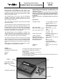
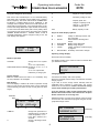
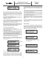
Bedienungsanleitung
Operating instructions
Notice d’utilisation
POWER PEAK “Plug & Charge”
No.: 8379
Bedienungsanleitung
Bestell Nr.
POWER PEAK PLUG &CHARGE
8379
Allgemeine Informationen
Abschaltautomatik sorgt für ein sicheres Abschalten.
Der Lader ist für den Betrieb an einer 12 V Batterie oder
einem leistungsfähigem, gut stabilisiertem 12 V oder
13,8 V Netzteil vorgesehen.
Achtung: Keine Autobatterie-Ladegeräte verwenden.
Sehr geehrter Kunde, wir freuen uns, daß Sie sich für die
Automatik-Ladestation POWER-PEAK PLUG & CHARGE
aus dem robbe Sortiment entschieden haben. Damit
besitzen Sie ein leistungsfähiges, mikroprozessorgesteuertes Ladegerät mit Akkumanagement.
Technische Daten
Trotz der einfachen Handhabung dieser Ladestation verlangt
die Bedienung eines hochwertigen, automatischen Ladegerätes wie dem POWER PEAK PLUG & CHARGE vom Anwender einige Kenntnisse.
Betriebsspannung:
Durch diese Anleitung wird es Ihnen schnell gelingen, sich
mit dem Gerät vertraut zu machen.
Stromaufnahme :
Akkunennspannungen:
Um dieses Ziel sicher zu erreichen, sollten Sie die
Bedienungsanleitung aufmerksam lesen, bevor Sie Ihre
neue Automatik-Ladestation in Betrieb nehmen. Wir wünschen Ihnen mit dem POWER PEAK PLUG & CHARGE viel
Freude und Erfolg.
Max. Schnelladestrom:
Erhaltungsladestrom:
Abschaltautomatik Laden:
Abschaltautomatik Entladen:
Der POWER PEAK PLUG & CHARGE ist ein Lade-/
Entladegerät für 4 bis 14 NC-Zellen mit den für den im
Modellsport typischen Kapazitäten von 0,25 bis 2,0 Ah.
Verlustleistug beim Entladen:
Max. Entladestrom:
Die Lade-/Entladeströme können entweder manuell zwischen 0,5 und 5 A eingestellt werden oder es kann der
Automatikmodus gewählt werden. Bei dieser Betriebsart wird
automatisch der optimale Lade-/ Entladestrom für den jeweiligen Akku eingestellt.
Schutzfunktionen:
Die Anzeige der wichtigsten Ladeparameter erfolgt über ein
großes und leicht ablesbares 2 x 16 Zeichen LC-Display.
Abmessungen:
Gewicht:
Die Abschaltung des Ladevorganges erfolgt automatisch bei
voll geladenem Akku nach dem Delta-Peak Verfahren. Die
Bedienelemente
LADEN/CHARGE-Taste:
ENTLADEN-LADEN/
DISCHARGE/CHARGE-Taste:
OUTPUT:
Display:
Lüfter:
12V Bleibatterie oder ein
leistungsfähiges, gut stabilisiertes 12V oder 13,8V
Netzteil (keine AutobatterieLadegeräte verwenden)
max. ca. 9 A
4,8V bis 16,8V (4 bis 14 NC
Zellen)
bis 20 V
5A
21-30V
4A
über 30 V 3 A
50-200 mA abhängig von
der Akkukapazität
Delta-Peak
automatisch auf ca. 0,8 V
pro Zelle
max. 35 W
5A
Eingangs- und ausgangsseitiger Verpolschutz, ausgangsseitiger
Kurzschlußschutz,
Temperaturüberwachung
der Endstufe
ca. 125 x155 x60 mm
550 g
Starten /Stoppen des Ladevorganges
Starten/Stoppen des Entlade-/Ladevorganges
Ladeausgang zum Laden von 4 bis 14 NC-Zelle
2 x 16 Zeichen
Zur Kühlung des Ladegerätes. Der Lüfter ist immer in Betrieb, wenn am
Output Strom fließt. Nicht abdecken!
DISPLAY
Lüfter
ENTLADEN-LADEN/
DISCHARGE-CHARGETaste
Stromversorgung
LADEN/CHARGE-Taste
OUTPUT
3
Bedienungsanleitung
Bestell Nr.
POWER PEAK PLUG &CHARGE
8379
Inbetriebnahme
S
Anzeige der Betriebsart (siehe unten)
Krokodilklemmen an eine 12 V Bleibatterie anschließen.
Unbedingt auf richtige Polung achten (rot = plus / schwarz =
minus). Im Display erscheint „robbe MODELLSPORT /
POWER PEAK PLUG & CHARGE“. Falls dieses Display jetzt
nicht erscheint, wurden entweder die Krokodilklemmen verpolt angeschlossen oder die Bleibatterie hat zu wenig
Spannung.
V
Z
NC-Akkuspannung in Volt
Vorzeichen für Kapazitätswert. Die eingeladene Kapazität ist durch „+“ und
die entnommene Kapazität durch „-“
gekennzeichnet
mAh
Akkukapazität in mAh
Ladekabel am Ausgang polrichtig einstecken und Akku am
Ladekabel anschließen (rot = plus / schwarz = minus).
Nach Anschluß eines Akkus (oder nach Betätigen irgendeiner Taste) verschwindet das Display „robbe MODELLSPORT
/ POWER PEAK PLUG & CHARGE“ und das Gerät ist
betriebsbereit. Es wird das Hauptdisplay angezeigt.
Die Symbole der Betriebsartanzeige besitzen folgende
Bedeutung:
R=
P=
D=
C=
F=
N=
0:00:00 0.00 A R
9.00 V + 0 mAh
READY
Laden oder Entladen inaktiv, Akku
angesteckt
PAUSE
Pause zwischen Entladen und Laden
DISCHARGE Akku wird entladen
CHARGE
Akku wird geladen
FINISH
Laden beendet, Erhaltungsladung
NO BATTERY Kein Akku angeschlossen
Display Betriebsspannungsanzeige:
Nur durch gleichzeitiges Betätigen von beiden Tasten zu
erreichen!
Nach Loslassen der beiden Tasten bleibt das Display etwa 3
Sekunden stehen.
Die Betriebsarten
LADEN:
Laden mit 0,5 bis 5 A (manuell)
bzw. 0,1 A bis 5 A (automatisch)
ENTLADEN vor LADEN
Entladen mit 0,5 bis 5 A (manuell)
bzw. 0,1 bis 5 A (automatisch),
gefolgt von einem Ladezyklus
INPUT VOLTAGE:
13.21V
Laden von Akkus
Displays
Akku polrichtig anschließen.
Eine kurze Betätigung der Taste „LADEN“ aktiviert das
automatische Ladeprogramm.
Der manuelle Ladestrom wird durch Dauerbetätigen der
Taste LADEN in 0,5 A Schritten eingestellt. Achtung: Die
Stromangaben der Akkuhersteller beachten.
Hinweis: Die in den Displays dargestellten Werte beziehen
sich auf einen 7-zelligen Akku. Die Zahlenwerte stellen
Beispiele dar.
Hauptdisplay:
Das Hauptdisplay ist in allen Betriebszuständen sichtbar.
Ausnahme: Nach dem Anschluß des Ladegerätes, bei der
manuellen Stromeinstellung und im Fehlerfall (Siehe
Fehlerdisplays).
H:MM:SS
A
Kontrollieren Sie die Ladeströme bei Fernsteuerakkus
auch
bezüglich
der
Kabelquerschnitte
und
Steckverbindungen.
S
Steht der gewünschte Ladestrom im Display, muß die Taste
losgelassen werden. Damit wird das Programm mit manuell
eingestelltem Ladestrom aktiviert.
0:16:21 3.50A C
12.75 V +900 mAh
V
H:MM:SS
A
Z
mAh
SET CHARGE
CURRENT AUTO
Ladezeit, Pausenzeit oder Entladezeit,
entsprechend der Betriebsart in
H=Stunden,MM=Minuten,
SS=Sekunden
SET CHARGE
CURRENT 0.5A
Lade - Entladestrom in Ampere
4
(automatisch)
(manuell)
Bedienungsanleitung
Bestell Nr.
POWER PEAK PLUG &CHARGE
8379
0:00:10 0.11A
9.08 V + 0mAh
manuell eingestellt werden. Geschieht das nicht, erfolgt die
Ladung mit automatischer Stromeinstellung.
C
Die Entladeschlußspannung wird automatisch eingestellt.
Nachdem der Entladevorgang beendet wurde, schließt sich
eine Pause (Betriebsart „P“) von 3 Minuten an. Danach wird
der Ladevorgang gestartet.
Das Hauptdisplay Betriebsart „C“ erscheint.
Nach dem Start erfolgt ein „Batterie Check“. Während des
Ladens prüft das Ladegerät im Minutenzyklus stromlos den
Akkuzustand und stellt danach den optimalen oder manuell
eingestellten Ladestrom wieder ein.
Soll der Akku nur entladen werden, ist ein Abbruch während
der Entladung durch die Taste „ENTLADEN/LADEN“
möglich.
Ein Abbruch durch die Taste „LADEN“ ist während des
Ladezyklusses möglich. Ist der komplette Zyklus durchlaufen, wird die Betriebsart „F“ angezeigt und das Signal
ertönt.
Während oder am Ende des Ladezyklusses können die
aktuellen Daten abgelesen werden.
Wird die Taste „LADEN“ kurz betätigt, wird der Ladevorgang
abgebrochen (Betriebsart = „R“).
Während und nach dem Laden wird die entnommene
Kapazität mit „-“ und die eingeladene Kapazität mit „+“
abwechselnd angezeigt.
Ist der Ladevorgang abgeschlossen, ertönt der Signalton und
die Betriebsart „F“ wird angezeigt. In Abhängigkeit vom
Akkutyp stellt das Gerät einen Erhaltungsladestrom zwischen 50 und 200 mA ein.
In Abhängigkeit vom Akkutyp stellt das Gerät anschließend
einen Erhaltungsladestrom zwischen 50 und 200 mA ein.
Beim Abnehmen des Akkus immer zuerst den Akku vom
Ladekabel trennen und dann das Ladekabel abziehen.
Fehlerdisplays:
Entladen - Laden von Akkus
Im Fehlerfall erscheint das entsprechende Fehlerdisplay und
das akustische Signal ertönt. Nach der Fehlerbeseitigung
und Quittieren durch irgendeine Taste wird das Signal
abgeschaltet und nach etwa 3 Sekunden erscheint das
Hauptdisplay.
Akku polrichtig anschließen.
Eine kurze Betätigung der Taste „Entladen - Laden“ aktiviert
das automatische Entlade - Ladeprogramm.
Der manuelle Entladestrom wird durch Dauerbetätigen der
Taste ENTLADEN-LADEN in 0,5 A Schritten eingestellt.
Achtung: Stromangaben der Akkuhersteller beachten.
INPUT BATTERY
LOW VOLTAGE
Kontrollieren Sie die Ladeströme bei Fernsteuerakkus
auch
bezüglich
der
Kabelquerschnitte
und
Steckverbindungen.
Betriebsspannung kleiner ca. 9,5 V
Steht der gewünschte Entladestrom im Display, muß die
Taste losgelassen werden. Damit wird das Programm mit
festem Entladestrom gestartet.
SET DISCHARGE
CURRENT AUTO
SET DISCHARGE
CURRENT 2.5A
CHECK THE BATT.
OPEN CIRCUIT
(automatisch)
Unterbrechung beim Laden, Laden/Entladen
manuell
OUTPUT BATTERY
REVERSE POLARITY
Verpolung am Ausgang
0:00:10 0.17A D
9.00 V - 0 mAh
NO BATTERY
INSERT BATTERY
Das Hauptdisplay Betriebsart „D“ erscheint.
Programmstart ohne angeschlossenen Akku
Nachdem der Entlade / Ladevorgang gestartet wurde, kann
mit der Laden-Taste der Strom für den folgenden Ladezyklus
5
Bedienungsanleitung
Bestell Nr.
POWER PEAK PLUG &CHARGE
8379
Anmerkungen
-
Vor Feuchtigkeit schützen.
-
Der Erhaltungsladestrom stellt sicher, daß die durch
Schnelladung eingeladene Kapazität im Akku
gespeichert bleibt.
-
Auf richtige Polung der Ausgänge achten.
-
Kurzschlüsse vermeiden.
-
Die maximalen Lade- und Entladeströme sind von der
Zellenzahl der Akkus abhängig.
-
Nicht direkter Sonneneinstrahlung aussetzen, Gerät nicht
abdecken.
-
Das Beenden des Ladens bzw. Entladens soll nicht durch
Abziehen des Akkus erfolgen.
-
Keine Akkus laden, die stark erwärmt sind. Akkus auf
Umgebungstemperatur abkühlen lassen.
-
Alle Fehlerdisplays bleiben nach Quittieren ca. 3
Sekunden in der Anzeige.
-
Das Gerät kann sich sich beim Entladevorgang sehr stark
erwärmen. Gerät vor Berührung auskühlen lassen.
-
Falls bei einigen, älteren Akkus Probleme mit der
automatischen Stromeinstellung auftreten, empfiehlt es
sich, in manueller Stromeinstellung zu laden.
-
Nur schnelladefähige und formierte Akkus benutzen.
-
Es dürfen nur NC-Zellen gleicher Kapazität und gleichen
Fabrikats im Verbund geladen werden.
-
Nicht zwei Akkus zum Laden parallel schalten.
-
Angaben der Akkuhersteller beachten.
-
Nur zum Laden von wiederaufladbaren Akkus geeignet.
-
Ladeströme der Höchstbelastung der am Akku befindlichen Kabel und Steckverbindungen anpassen.
-
Sollte die Stromwahl gesperrt sein, befindet sich der Akku
kurz vor der Abschaltung.
Ein Senderakku darf nur unter Berücksichtigung folgender Hinweise geladen werden:
Verpolschutzdiode im Ladezweig des Senders überbrücken,
oder Akkuanschluß vom Sender trennen und Direktladekabel
verwenden.
Die meisten Sender besitzen diese Verpolschutzdiode. Das
Überbrücken sollte von einem Fachmann, am besten vom
robbe - Service, durchgeführt werden.
Ein
Laden
mit
Verpolschutzdiode
kann
zu
Fehlabschaltungen und zur Zerstörung des Akkus oder
Ladegerätes führen.
-
Hinweise zur EMV
Vor Inbetriebnahme des Gerätes muß das Ladekabel mittels
beigefügtem Ferritkern gemäß Skizze modifiziert werden, um
die EMV-Bestimmungen einzuhalten.
Empfohlene Direktladekabel:
No. 8262
F - Serien Sender
No. 8263
Internationale Serie
Sicherheitshinweise
-
Bei längerem Nichtgebrauch das Gerät von der
Stromquelle trennen und eventuell angeschlossenen
Akku abnehmen.
-
Beim Aufstellen auf freie Kühlöffnungen zur
Luftzirkulation achten (nicht auf Teppich oder Filz stellen).
-
robbe Modellsport GmbH & Co. KG
Technische Änderungen vorbehalten
Ladegerät und Akkus nicht auf brennbaren Unterlagen
betreiben und nicht unbeaufsichtigt lassen.
6
robbe Modellsport GmbH & Co. KG
Metzloserstr. 36
36355 Grebenhain HJJ
Operating instructions
Order No.
POWER PEAK PLUG &CHARGE
8379
Introduction
The unit features a Delta Peak circuit which terminates the
charge process automatically when the battery is full. The
digital full detection circuit provides a reliable method of terminating the process.
The unit is designed to be powered by a 12 V lead-acid
battery, but can also be used with a well stabilised 12 V
or 13.8 V mains power supply provided that it is powerful enough.
Caution: do not use a car battery charger to power the
unit.
Dear customer, congratulations on your choice of the
POWER PEAK PLUG & CHARGE automatic battery charging station from the robbe range. You now possess a highperformance charger for your NiCd batteries with includes
battery management facilities.
This charging station is very easy to use, but nevertheless
operating a high-quality automatic charger such as the
POWER PEAK PLUG & CHARGE does call for some knowledge on the part of the user.
Specification
These instructions are intended to help you become familiar
with the unit quickly.
Operating voltage:
To ensure that you are able to exploit the charger to the full,
please read right through these operating instructions very
carefully before you use your new automatic charging station
for the first time. We hope you enjoy using your POWER
PEAK PLUG & CHARGE, and we are confident that you will
have good results with it over a long period.
Max. current drain:
Nominal NC battery voltage:
The POWER PEAK PLUG & CHARGE is a charger / discharger designed for use with NC batteries consisting of 4 to
14 cells. The cell capacity should be within the range 0.5 to
2.0 Ah, which covers most types used in modelling.
Trickle charge current:
Max. rapid charge current:
Charge termination:
Discharge termination:
Discharge power dispersion:
Max. discharge current:
Protective functions:
The charge / discharge currents can either be set manually
within the range 0.5 to 5 A, or you can select the automatic
mode. In this mode the optimum charge / discharge current
is selected automatically to suit the battery connected to the
unit.
The essential charge parameters are displayed on a large,
clearly legible 2 x 16 character LCD screen.
Controls
CHARGE button:
DISCHARGE-CHARGE button:
OUTPUT:
Display:
Fan:
Dimensions:
Weight:
12 V car battery or a power
ful, well stabilised 12 V or
13.8 V
mains power supply (do not
use a car battery charger)
approx. 9 A
4.8 V to 16.8 V (4-14 NC
cells)
up to 20 V 5 A
21 - 30 V
4A
over 30 V 3 A
50 to 200 mA, depending on
NC battery capacity
Delta Peak
Autom. at appr. 0.8V per cell
max. 35 W
5A
Reverse polarity
Short-circuit (output)
Output stage temperature
monitor
approx. 125 x 155 x 60 mm
550 g
For starting and stopping the charge process
For starting and stopping the discharge /
charge process
Charge output for charging 4 to 14 NC cells
2 x 16 character LCD screen
Cools the charger. The fan operates continuously when current is flowing at the output. Do not obstruct the fan!
SCREEN
Fan
ENTLADEN-LADEN/
DISCHARGE-CHARGEButton
Power supply
LADEN/CHARGE-Button
OUTPUT
7
Operating instructions
Order No.
POWER PEAK PLUG &CHARGE
8379
Using the charger for the first time
S
Display of mode of operation
First connect the crocodile clips to a 12 V lead-acid battery.
Take great care to maintain correct polarity (red = positive /
black = negative). The screen will now show „ROBBE MODELLSPORT / POWER PEAK PLUG & CHARGE“. If this
message does not appear, either the crocodile clips are connected with reversed polarity, or the lead-acid battery is flat.
Connect the charge lead to the output sockets on the charger. Now connect the NiCd battery with correct polarity. When
you connect an NC pack (or press any button) the message
„ROBBE MODELLSPORT / POWER PEAK PLUG &
CHARGE“ disappears, and the charger is ready to use. The
main display now appears.
V
NC battery voltage in Volts
Z
Capacity prefix. The
charged-in capacity is indi
cated by „+“, and the dis
charged capacity by „-“.
mAh
Battery capacity in mAh
Key to the mode display symbols:
0:00:00 0.00A R
9.00V + 0 mAh
R
=
P
=
D
C
F
=
=
=
N
=
READY
Charge or discharge inactive, battery connected
PAUSE
Pause between discharge and
charge
DISCHARGE Battery being discharged
CHARGE
Battery being charged
FINISH
Charge completed, trickle charging
in progress
NO BATTERY No battery connected to charger
Operating voltage display:
Press both buttons to display.
Modes of operation
The display remains on the screen for about 3 seconds after
you release the buttons.
CHARGE:
Charge at 0.5 to 5 A (manual)
or 0.1 to 5 A (automatic)
DISCHARGE before CHARGE: Discharge at 0.5 to 5 A
(manual)
or 0.1 to 5 A (automatic,
followed by a charge cycle
INPUT VOLTAGE
13.21V
Charging batteries
Screen displays
Note: the values shown here refer to a 7-cell battery. They
are only intended to be examples.
Connect the NC battery with correct polarity.
Press the „CHARGE“ button briefly to activate the automatic
charge program.
If you wish to set the charge current manually hold the
CHARGE button pressed in continuously; the current
advances in 0.5 A increments. Caution: observe the charge
current limits stated by the battery manufacturer.
Main display:
The main display is visible in all modes of operation except
when you first connect the charger, when you are setting the
current manually, and when an error occurs (see Error messages).
If you are charging a radio control system battery check
that the cable cross-section and connector do not place
further restrictions on the charge rate.
H:MM:SS
A
S
Release the button once the correct charge current is shown
on the screen. This activates the program using the manually adjusted charge current.
0:16:21 3.50A C
12.75V +900 mAh
V
H:MM:SS
A
Z
mAh
SET CHARGE
CURRENT AUTO
Charge time, pause time or
discharge time, according to
mode of operation, in H =
hours, MM = minutes, SS =
seconds
Charge / discharge current
in Amps
SET CHARGE
CURRENT 0.5A
8
(automatic)
(manually)
Operating instructions
Order No.
POWER PEAK PLUG &CHARGE
8379
The discharge voltage is fixed, and is detected automatically.
When the discharge process is finished there follows a pause
(mode „P“) lasting three minutes. The charge process then
starts.
0:00:10 0.11A C
9.08V + 0 mAh
If you wish to discharge the battery only, you can interrupt the
cycle at this point by pressing the „DISCHARGE-CHARGE“
button during the discharge process.
You can interrupt the process at any time during the charge
cycle by pressing the „CHARGE“ button. Once the complete
cycle has been completed, mode „F“ appears on the screen,
and you will hear the beeper sound.
During and after the charge process the screen shows the
discharged capacity with the „-“ prefix, and the charged-in
capacity with the „+“ prefix; the two values alternate on the
screen.
The main screen for mode „C“ now appears.
Once the program is started, the unit carries out a „battery
check“. During the charge process the charger checks the
state of the battery without current every minute, and adjusts
the automatic or manual charge current to the optimum level
afterwards.
The current data is displayed on the screen during the
charge cycle and at the end of the cycle.
Pressing the „CHARGE“ button briefly always interrupts the
charge process (mode „R“).
Once the charge process is finished, the beeper sounds and
mode „F“ is displayed. The charger now switches to a trickle
charge using a current within the range 50 to 200 mA,
depending on the type of battery connected to it.
The charger now switches to a trickle charge using a current
within the range 50 to 200 mA, depending on the type of battery connected to it.
When disconnecting the NC battery always disconnect
the pack from the charge leads first, and only then disconnect the charge leads from the charger.
Error messages:
If an error occurs, the appropriate error message appears on
the screen and you will hear the beeper sound. After you
eliminate the problem and cancel the message by pressing
any button, the warning signal is switched off, and after about
three seconds the main screen reappears.
Discharging / charging batteries
Connect the NC battery with correct polarity.
Press the „DISCHARGE“ button briefly to activate the automatic discharge program.
If you wish to set the discharge current manually hold the
DISCHARGE-CHARGE button pressed in continuously; the
current advances in 0.5 A increments. Caution: observe the
current limits stated by the battery manufacturer.
If you are discharging a radio control system battery
check that the cable cross-section and connector do not
place further restrictions on the charge rate.
INPUT BATTERY
LOW VOLTAGE
Input voltage lower than about 9.5 V
CHECK THE BATT.
OPEN CIRCUIT
Release the button once the correct discharge current is
shown on the screen. This activates the program using the
fixed discharge current.
SET DISCHARGE
CURRENT AUTO
(automatic)
SET DISCHARGE
CURRENT 2.5A
(manually)
Open circuit during the charge or charge /
discharge process
OUTPUT BATTERY
REVERSE POLARITY
Reverse polarity at the charger output
0:00:10 0.17A D
9.00V - 0 mAh
NO BATTERY
INSERT BATTERY
The main screen for mode „D“ now appears.
Once the discharge / charge program has started, you can
set the current for the subsequent charge cycle manually
using the Charge button. If you do not do this, the charge
process will be carried out with the current set automatically.
Program started with no battery connected
9
Operating instructions
Order No.
POWER PEAK PLUG &CHARGE
8379
Notes
-
Protect the unit from damp.
The trickle charge process ensures that the capacity charged
into the pack during the rapid-charge process is maintained
until the battery is used.
-
Take care to ensure correct polarity at the output sockets.
-
Avoid short-circuits.
The maximum charge and discharge currents vary according
to the number of cells in the pack.
-
Do not subject the charger to direct sunshine. Do not
cover the unit when it is running.
Never terminate the charge or discharge cycle by disconnecting the battery.
-
Do not attempt to recharge a NC pack which is already
hot. Allow packs to cool down to ambient temperature
first.
-
The charger can become very hot during the discharge
process. Allow it to cool down again before touching it.
-
Use only NC packs which are stated to be capable of
rapid-charging. Cells in a pack must be balanced (equal
state of charge).
-
Packs must consist of NC cells of the same capacity,
make and type.
-
Do not charge two batteries in parallel.
-
Keep to the battery manufacturer’s recommendations.
-
Suitable only for charging rechargeable batteries.
-
Adjust the charge current so that it does not exceed the
maximum load of the cable and connector atached to the
battery.
All error messages remain on the screen for about three seconds after you have cancelled them.
If you encounter problems with automatic current setting
when using fairly old batteries, we recommend that you
charge them using the manual current setting facility.
If you find that you cannot select a current, this means that
the charger is about to terminate the process.
Please note the following points before you attempt to
charge a transmitter battery:
You will need to by-pass the reverse polarity diode in the
transmitter’s charge circuit, or disconnect the battery from the
transmitter and use a direct charge lead.
Most transmitters are now fitted with this reverse polarity
guard diode. If no method of by-passing it is fitted, have the
modification carried out by a specialist, or - even better - by
the robbe Service Department.
Charging a transmitter battery with the reverse polarity diode
in circuit will cause the charger to terminate the process
early, and may result in permanent damage to the battery
and/or the charger.
-
Direct charge leads:
No. 8262
F-series transmitters
No. 8263
International series
IEC interference suppression
Safety notes
-
Disconnect the charger from the power source if it is not
to be used for a long period. Disconnect any NC packs
from it at the same time.
-
Set up the unit on a hard surface (not carpet or felt)
before using it, so that its cooling slots are unobstructed
for good air circulation.
-
Before you use the charger the charge lead must be modified
by passing it through the ferrite ring supplied, as shown in the
sketch below. This ensures that the charger meets IEC suppression regulations.
robbe Modellsport GmbH & Co. KG
We reserve the right to alter technical specifications.
Do not place the charger or batteries on a flammable surface when in use, and never leave the charger running
unsupervised.
10
Notice d’utilisation
Réf.
POWER PEAK PLUG &CHARGE
8379
Informations générales
Le chargeur est conçu pour fonctionner à partir d’une
batterie de voiture 12 volts ou d’un bloc d’alimentation
secteur puissant, parfaitement stabilisé de 12 volts ou
de 13,8 volts.
Cher Client, nous nous réjouissons de votre choix, la station
de charge automatique POWER-PEAK BRANCHER &
CHARGER est un chargeur particulièrement performant;
piloté par microprocesseur et équipé d’un dispositif de gestion des accus.
Attention : ne pas utiliser de chargeur pour batterie de
voiture.
Bien que la manipulation de cet station de charge soit relativement simple, l’exploitation du chargeur automatique
POWER-PEAK BRANCHER & CHARGER exige toutefois un
certain nombre de connaissances préalables.
Cette notice vous aidera à vous familiariser rapidement avec
cet appareil.
Caractéristiques techniques
Tension de service:
Pour atteindre sûrement cet objectif, lire attentivement cette
notice avant de mettre votre nouvelle station de charge en
service. Nous vous souhaitons beaucoup de satisfaction et
de succès avec votre POWER-PEAK BRANCHER &
CHARGER.
L’appareil POWER-PEAK BRANCHER & CHARGER et un
chargeur/déchargeur conçu pour charger/décharger de 4 à
14 éléments Cd-Ni avec des capacités typiques des disciplines du modélisme, de 0.25 à 2,0 Ah.
Consommation:
Tension nom. des accus:
Courant de charge
rapide maximum
Courant de maintien:
alimentation à partir d’une batterie 12 volts de voiture ou à
partir d’un bloc d’alimentation
secteur parfaitement stabilisé
de 12 ou 13,8 volts.
max. approx. 9 A
4,8 à 16,8 volts (4 à 14 éléments Cd-Ni)
jusqu’à 20 volts
5A
21 à 30 volts
4A
au-dessus de 30 volts
3A
50 à 200 mA dépendant de la
capacité des accus
Procédure de commutation
autom. en fin de charge:
Delta-Peak
Les courants de charge/décharge peuvent soit être réglés
manuellement entre 0,5 et 5 A soit sélectionnés automatiquement en mode automatique. Avec ce dernier mode, le
courant de charge/décharge optimal est sélectionné automatiquement pour l’accu raccordé.
Procédure de commutation
autom. en fin de décharge: réglage automatique avec
0,8 volt par élément environ
Courant de décharge max.: 5 A
L’affichage des paramètres de charge essentiel est assuré
par un écran à cristaux liquides de 2 x 16 caractères, parfaitement dimensionné et bien lisible.
Fonctions de protection:
La commutation en fin de charge intervient automatiquement
lorsque l’accu est entièrement chargé via le processus DeltaPeak. L’automatisme de commutation se charge d’une commutation parfaitement efficace.
Encombrement:
Poids:
inversion des polarités entrée
et sortie
courts-circuits sortie
surveillance de la température
de l’étage final
approx. 125 x 155 x 60 mm
approx. 550 g
Éléments de commande
Touche de charge LADEN/CHARGE:
Touche de décharge/charge
ENTLADEN-LADEN/DISCHARGE-CHARGE
OUTPUT
Écran:
Ventilateur:
pour lancer et stopper la procédure de charge
pour lancer et stopper la procédure de décharge/charge
sortie de charge pour 4 à 14 éléments Cd-Ni
écran de 2 lignes x 16 caractères
pour le refroidissement du chargeur. Le ventilateur est toujours en
marche lorsque du courant sort de la sortie. Ne pas le couvrir !
ECRAN
Ventilateur
Touche de déchargecharge
ENTLADEN-LADEN
DISCHARGE-CHARGE
Alimentation électrique
Touche de charge
LADEN/CHARGE
OUTPUT (Sortie)
11
Notice d’utilisation
Réf.
POWER PEAK PLUG &CHARGE
8379
Mise en service du chargeur
Pour raccorder le chargeur POWER-PEAK BRANCHER &
CHARGER, accrocher les pinces crocodiles aux bornes de la
batterie au plomb 12 volts. Veiller impérativement à respecter
les polarités (rouge = +, noir = -). Sur l’écran apparaît,
„ROBBE MODELLSPORT / POWER-PEAK BRANCHER &
CHARGER“. Si, à ce moment-là, rien n’apparaît sur l’écran
c’est soit que les pinces crocodiles sont inversées ou que la
batterie ne dispose pas d’assez de courant.
S
affichage du mode
V
tension de l’accu Cd-Ni en volts
Z
préfixe de la valeur capacitive. La capacité chargée
est repérée par „+“ et la capacité décharge par „-“.
mAh
capacité de l’accu en mAh
Les symboles de l’affichage du mode ont la signification
suivante:
Planter le cordon de charge correctement (polarités) à la sortie et raccorder l’accu au cordon de charge d’un accu (rouge
= plus / noir = moins).
Après avoir raccordé un accu (ou après avoir appuyé sur une
touche quelconque) sur l’écran disparaît la mention „ROBBE
MODELLSPORT / POWER-PEAK BRANCHER & CHARGER“ et l’appareil est en ordre de marche, L’écran principal
apparaît.
R = READY
charge ou décharge inactives, accu
branché
P = PAUSE
pause entre le cycle de décharge et de
charge
D = DISCHARGE l’accu est en cours de déchargement
C = CHARGE
l’accu est en cours de charge
F = FINISH
charge achevée, charge de maintien en
cours
N = NO BATTERY pas d’accu raccordé
0:00:00 0.00A R
9.00 V + 0 mAh
Affichage de la tension de service sur l’écran:
Ne peut être réalisé qu’en appuyant sur les deux touches
simultanément !
Une fois que les touches ont été relâchées, l’affichage subsiste pendant environ 3 secondes sur l’écran.
Les modes
CHARGE:
charge avec 0,5 à 5 A
(manuel) ou de 0,1 à 5 A
(automatique)
INPUT VOLTAGE:
13.21V
DÉCHARGE avant CHARGE: décharge avec 0,5 à 5 A
(manuel) ou de 0,1 à 5 A
(automatique) suivie d’un
cycle de charge
Charge des accus
Écrans
Raccorder les accus en veillant à la correction de la polarité.
Une pression brève sur la touche „LADEN“ active le programme de charge automatique.
Le courant de charge manuel est réglé par une pression continue sur la touche CHARGE en étapes de 0,5 A. Attention
: tenir compte des indications concernant le courant
fournies par le fabricant de l’accu.
À noter: les valeurs figurant dans un écran se réfèrent à un
accu de 7 éléments. Le valeurs chiffrées constituent des
exemples.
Écran principal:
L’écran principal apparaît quel que soit le mode de service
sélectionné, à l’exception du branchement du chargeur avec
un réglage manuel du courant et en cas d’anomalie (cf. écran
d’anomalie).
H:MM:SS
A
S
Vérifier les courants de charge sur les accus d’ensembles de radiocommande également du point de vue de la
sections des brins et des connecteurs.
Lorsque le courant de charge souhaité figure sur l’écran,
lâcher la touche. Le programme avec courant de charge fixé
manuel est alors engagé.
0:16:21 3.50A C
12.75 V +900 mAh
V
H:MM:SS
A
Z
mAh
SET CHARGE
CURRENT AUTO
durée de la charge, durée des pauses ou
durée de la décharge du mode en H =
heures, MM = minutes, SS = secondes
SET CHARGE
CURRENT 0.5A
courant de charge - décharge en ampères
12
(automatique)
(manuel)
Notice d’utilisation
Réf.
POWER PEAK PLUG &CHARGE
8379
Le courant de fin de décharge est programmé automatiquement. Une fois que la décharge est terminée, intervient une
pause (mode „P“) de 3 minutes. Ensuite s’amorce la charge.
0:00:10 0.11A C
9.08 V + 0 mAh
Le mode „C“ de l’écran principal apparaît.
S’il s’agit seulement de décharger l’accu, il est possible d’interrompre le cycle en fin de décharge avec la touche „ENTLADEN/LADEN).
Après le démarrage intervient un „Battery check“ (contrôle de
l‘accu). Pendant la charge, le chargeur contrôle l’état de l’accu avec un cycle d’une minute et détermine le courant optimal ou le courant programme manuellement.
Une interruption avec la touche „LADEN“ est possible pendant le cycle de charge. Lorsque le cycle de charge est
achevé c’est le mode „F“ qui apparaît sur l’écran et le signal
sonore retentit.
Pendant ou en fin du cycle de charge il est possible de lire
les informations en cours sur l’écran.
Lorsque la touche „LADEN“ est brièvement activée, la procédure de charge est en principe interrompue (mode = „R“).
Pendant et après la charge la capacité déchargée est
présentée avec „-“ alternativement avec la capacité charge
„+“.
En fonction du type d’accu le chargeur établit un courant de
charge de maintien de 50 à 200 mA.
Lorsque la procédure de charge est achevée un signal
sonore retentit et le mode „F“ apparaît. En fonction du type
de l’accu l’appareil établit un courant de charge de maintien
de 50 à 200 mA.
Écrans d’anomalies:
Pour détacher l’accu, séparer toujours d’abord l’accu du
cordon de charge puis le cordon de charge du chargeur.
En cas d’anomalie l’écran d’anomalie correspondant apparaît et le signal sonore retentit. Après avoir supprimé l’anomalie et lÄavoir validée à l’aide d’une touche queconque. le
signal est coupé et après 3 secondes environ l’écran principal apparaît.
Décharge - charge d’accus
Raccorder l’accu en tenant compte des polarités.
Actionner brièvement la touche „Entladen - Laden“ qui
engage le programme automatique de décharge - charge.
Régler manuellement le courant de charge en maintenant la
pression sur la touche ENTLADEN/LADEN, en étapes de 0,5
A. Attention : tenir compte des indications fournies par
le fabricant des accus.
INPUT BATTERY
LOW VOLTAGE
Vérifier les courants de charge sur les accus d’ensembles de radiocommande également du point de vue de la
sections des brins et des connecteurs.
Tension de service inférieure à approx. 9,5 volts.
Lorsque le courant souhaité figure sur l’écran, lâcher la
touche ce qui lance le programme de décharge.
SET DISCHARGE
CURRENT AUTO
CHECK THE BATT.
OPEN CIRCUIT
(automatique)
Interruption du cycle de charge, décharge/charge.
SET DISCHARGE
CURRENT 2.5 A
(manuel)
OUTPUT BATTERY
REVERSE POLARITY
0:00:10 0.17A D
9.00V - 0 mAh
Inversion de polarité à la sortie
NO BATTERY
INSERT BATTERY
Sur l’écran principal apparaît le mode „D“.
Une fois que la procédure de décharge/charge a été lancée,
il est possible de régler manuellement le courant pour le
cycle de charge qui suit à l’aide de la touche de charge. Si ce
n’est pas le cas, la charge interviendra avec un courant
déterminé automatiquement par le chargeur.
Démarrage du programme sans accu raccordé.
13
Notice d’utilisation
Réf.
POWER PEAK PLUG &CHARGE
8379
Remarques
-
Ne pas disposer l’accu ni le charge sur un support inflammable et ne pas les laisser sans surveillance.
Le courant de charge de maintien assure que la capacité
chargée par la charge rapide reste dans l’accu.
-
Protéger de l’humidité.
-
Veiller à observer la polarité des sorties.
-
Éviter les courts-circuits.
-
Ne pas exposer au rayonnement solaire direct.
-
Ne pas charger d’accu dont la température est excessive.
Les laisser au préalable prendre la température
ambiante.
-
Ne charger en commun que des éléments de capacité et
de fabrication identiques.
-
Ne pas raccorder en parallèles deux accus pour les
charger simultanément.
-
Tenir compte des informations fournies par le fabricant
des accus.
-
Le chargeur n’est conçu que pour la charge d’accus
rechargeables.
-
Ajuster les courants de charge en fonction de la charge
maximale du cordon et des connecteurs solidarises de
l’accu.
Les courants de charge et de décharge maximaux dépendent du nombre d’éléments de l’accu.
La fin d’une charge ou d’une décharge ne doit en aucun cas
être réalisée en retirant le branchement de l’accu.
Tous les écrans d’anomalie restent affichés pendant 3 secondes approx. après validation de l’anomalie.
Si des difficultés apparaissent pour le réglage du courant de
certains accus anciens, il est recommandé de chargé avec
programmation manuelle du courant de charge.
Si la sélection du courant est bloqué, cela signifique que l’accu se trouve juste avant la commutation.
Un accu d’émetteur ne peut être chargé qu’en tenant compte
des indications suivantes:
shunt de la diode de protection contre les inversions de
polarité dans le raccord de charge de l’émetteur ou détacher
le branchement de l’accu de l’émetteur et utiliser un cordon
de charge directe.
La plupart des émetteurs disposent d’une diode de protection
contre les inversions de polarité. Le shunt doit être réalisé
par un spécialiste, de préférence par le service après-vente
robbe.
Indications concernant les directives EMV (Normes électriques)
Une charge avec diode de protection contre les inversions de
polarité peut provoquer des commutations inopinées ou la
destruction de l’accu ou du chargeur.
-
Cordons de charge directe recommandé:
réf. 8262
émetteurs de la série F
réf. 8263
série internationale
Consignes de sécurité
-
Lorsque l’appareil n’est pas utilisé pendant un certain
temps, le désolidariser de sa source d’alimentation et
retirer éventuellement l’accu raccordé.
Avant de mettre l’appareil en service, il faut modifier le cordon de charge avec le noyau de ferrite joint selon les indications du schéma afin de préserver les directives EMV.
-
Lors de la mise en place de l’appareil, veiller à ce que ses
ouvertures d’aération restent dégagées (pas de tapis ou
de feutre).
robbe Modellsport GmbH & Co. KG
Sous réserve de modification technique.
14