1
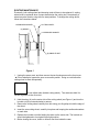
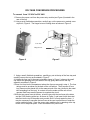
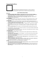
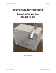
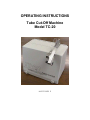
OPERATING INSTRUCTIONS
Tube Cut-Off Machine
Model TC-20
90-2333 REV F
SAFETY NOTICE
To ensure safe and satisfactory operation of this equipment, it is essential that the
ground wire of the power cord is connected to a ground that complies with all national,
state, and local electrical codes.
Before using this equipment read the instructions carefully paying particular attention to
potential hazards arising from its use.
Even with the power switch turned off there is still voltage on the input side of the switch
and therefore the equipment must be unplugged before lifting the front cover.
This equipment contains a safety interlock switch for the lid. Closure screws must be
fully tightened for equipment to operate.
SAFETY GLASSES SHOULD ALWAYS BE WORN WHILE MACHINE IS IN
USE.
WARNING
DO NOT CUT TUBING NEAR ORGANIC VAPORS.
DESCRIPTION
The Tube Cut-Off Machine has been designed for light or intermittent duty using a highspeed, dry abrasive cut-off wheel housed in a protective cabinet. The motor speed, wheel,
and cutting arm are carefully matched and aligned to provide safe, square cutting of 1/16, 1/8
and 1/4 inch (1.6, 3.2 and 6.4 mm) OD stainless steel tubing with ID down to 0.008 inches
(0.2 mm). The unique dressing tool deburrs by shaving the OD and ID with hard tool-steel
cutting edges. Properly maintained, the TC-20 should provide years of trouble free
operation.
INSTALLATION AND USE
1.
2.
3.
4.
5.
6.
Plug the Tube Cut-Off Machine into a properly grounded outlet. Be sure that the line voltage
matches the voltage rating on the left side of the unit.
For 115V operation use 93-5062: Fuse 5 amp SLO-BLO, 1 each
Install fuse opposite clip on fuse holder, insert fuse holder so 115V appears through window in
fuse door.
For 230Voperation use 93-5062: Fuse 5 amp SLO-BLO, 2 each
Remove clip on fuse holder to install both fuses, insert fuse holder so 230V appears through
window in fuse door.
Place the tubing to be cut into the vise-clamp on the end of the cutting arm and tighten. Be
certain the tubing is as straight as possible for best results.
Turn on the high-speed abrasive wheel and lower the arm to direct the tubing into the slot.
(Safety glasses should be worn while machine is in use.) Raise and lower the arm several
times to make certain the tube-end in the vise arm is square cut. Turn off the cutting wheel.
Discard the short piece that has been cut off, turn the tube around in the vise and square-cut
the other end. Measure carefully before cutting. * The tube in the vise is now ready for
deburring. The piece not held by the vise arm usually will not be square or suitable for
deburring, unless it is also firmly captured during the cutting operation.
Deburr by inserting the tube into the appropriate size dressing tool on the opposite end of the
cutting arm and turning the knurled nut clockwise. Always turn the dressing tool in the same
direction, like a pencil sharpener. Light pressure and several revolutions are sufficient in most
cases to remove burrs from the OD and ID of the tubing. Results will improve with practice.
*Scale on lid is for reference only.
1
ROUTINE MAINTENANCE
Eventually, both cutting wheel and dressing tools will have to be replaced. A cutting
wheel must be replaced when it wears down below the cutting slot. Occasionally, a
wheel may also break or clog with fine steel particles .To change the cutting wheel,
follow the instructions below.
CARDBOARD WASHER
CUTTING WHEEL
(A) ARBOR
CARDBOARD WASHER
(B) KNURLED NUT
Figure 1
1. Unplug the power cord, and then remove the two thumbscrews on the front cover.
Do not attempt to bypass the open cover safety switch. Doing so could allow the
cutting wheel to start unexpectedly.
Do not adjust arbor (behind cutting wheel). Two setscrews hold it in
correct alignment to the cover slot.
2. Hold the arbor (A) on the motor side of the cutting wheel (see Figure 1) and turn the
knurled nut (B) counterclockwise to remove.
3. Remove the cutting wheel carefully from hub using your fingertips to hold the edge of
the wheel.
4. Insert the new cutting wheel, carefully into place and keeping the cardboard washers
on each side.
5. Replace the knurled nut while holding the arbor on the motor side. The knurled nut
should be tightened to its original finger-light position.
6. Before closing the cover, brush or vacuum dust from inside the case.
2
A dressing tool should be replaced when it gets dull and pushes rather than shaves
burrs. The needle insert (see Figure 2) that deburrs the ID will break or wear out more
frequently than the body that deburrs the OD. To replace the dressing tool, follow the
Instructions below.
1. Remove the dressing tool from the vise arm by opening the C-ring. The needle insert
is held inside the tool body by a set screw.
2. Note the position of the needle Insert cutting tip before loosening the set screw.
Remove and replace the needle to the same position. Normally the back of the insert
will be flush with the back of the tool body.
3. Tighten the set screw and replace the dressing tool and C-ring.
3
Spare Parts
10-0124
10-0116
10-1016
10-0118
10-1018
10-1042
93-5062
93-5062
Replacement cutting wheel, pack of 3
1/16” Dressing tool
Replacement needle insert for 1/16” dressing tool
1/8” Dressing tool
Replacement needle Insert for 1/8” dressing tool
1/4” Dressing tool
Fuse, 5 Amp Slo-Blo (115V)
2 each Fuses, 5 Amp Slo-Blo (230V)
Figure 2
Figure 3
4
VOLTAGE CONVERSION PROCEDURES
To convert from 115 VAC to 230 VAC:
1. Remove the power cord from the power entry module (see Figure 4) located in the
rear of the unit.
2. Using a small, flat-blade screwdriver, carefully pry out the power entry module cover
at point A, Figure 4. The hinged cover will swing down as shown in Figure 5.
A
Fuse Tray
Hinged cover
Figure 4
Figure 5
3. Using a small, flat-blade screwdriver, carefully pry out at the top of the fuse tray and
carefully remove the tray as illustrated in Figure 5.
4. Holding the fuse tray in the exact orientation shown in Figure 6, observe the small
clip shown and grasping at the two sides of the clip gently remove from the tray
assembly as shown in Figure 6.
5.Place one fuse into the compartment where the clip was removed in step 4. The fuse
ratings must be as shown on the back of the unit cabinet. The European 20 mm
long fuses must be placed fully to the rearmost end of the tray (closest to the metal
tabs extending from the tray), or contact will not be made and the unit will not
operate. Both fuses must be present to complete the circuit.
6.With the two proper fuses in the tray, orient the tray with the two fuses at the sides
and the 230V marking at the top, as shown in Figure 5, and insert it with the metal
tabs first into the top of the power entry module until it is firmly seated in place. It
may be necessary to squeeze the two fuses at the rear to permit them to enter the
power module housing. Close the power entry module cover by pressing at the top
center until it snaps into place. Insert a suitable 230V power cord.
5
To convert from 230 VAC to 115 VAC:
1. Remove the power cord from the power entry module (see Figure 4) located in the
rear of the unit.
2. Using a small, flat-blade screwdriver, carefully pry out the power entry module cover
at point A, Figure 4. The hinged cover will swing down as shown in Figure 5.
3. Using a small, flat-blade screwdriver, carefully pry out at the top of the fuse tray and
carefully remove the tray as illustrated in Figure 5.
4. Observe the shorting clip in figure 6 and remove the fuse present in the fuse tray
where the shorting clip will go by gently lifting it up at the rearmost end of the tray
(where the metal tab extends) and removing the fuse from its retaining clip.
5. Observe the shorting clip placement as shown in Figure 6. Place a shorting clip by
hand onto the tray as follows. The tray must be oriented as drawn (the marking
PRSR will be at the top of the fuse tray front). The clip must be oriented as shown
with the “finger” at the center pointing toward the front of the tray. Do not bend this
finger or the required connections will not be made. Grasping the clip only at the
sides, slide it down into place on the tray. The base of the clip will insert into the
cavity in the tray when it is placed in the correct position. Place one fuse into the
compartment in the side of the fuse tray opposite the side with the clip. The fuse
rating must be as shown on the back of the unit cabinet. A 20 mm long European
fuse must be placed fully to the rearmost end of the tray (closest to the metal tabs
extending from the tray) or contact will not be made and the unit will not operate.
Both the clip and the fuse must be present in their proper places or the unit will not
operate. With the clip and proper fuse in the tray, orient the tray with the fuse at the
side and the 115V marking at the top, as shown in Figure 5, and insert it with the
metal tabs first into the top of the power entry module until it is firmly seated in place.
It may be necessary to squeeze the fuse at the rear to permit it to enter the power
module housing. (If the clip and fuse are on the incorrect sides of the tray, it will not
be possible to place the tray into the power entry module). Close the power entry
module cover by pressing at the top center until it snaps into place. Insert a suitable
115V power cord.
Clip
Rearmost
end of tray
Figure 6
6
General Safety Rules
WARNING! Read and understand all instructions. Failure to follow all
instructions listed below may result in electric shock, fire and/or serious personal injury.
SAVE THESE INSTRUCTIONS
Work Area
•
Keep your work area clean and well lit. Cluttered benched and dark areas invite accidents.
•
Do not operate power tools in explosive atmospheres, such as in the presence of flammable
liquids, gases, or dust. Power tools create sparks which may ignite the dust or fumes.
•
Keep bystanders, children, and visitors away while operating a power tool. Distractions can
cause you to lose control of the tool.
Electrical Safety
•
Do not abuse the cord. Never use the cord to carry the tool. Keep cord away from heat, oil, sharp
edges, or moving parts. Replace damaged cords immediately. Damaged cords may create a fire.
Personal Safety
•
Stay alert, watch what you are dong and use common sense when operating a power tool. Do
not use tool while tired or under the influence of drugs, alcohol, or medication. A moment of inattention
while operating may result in serious personal injury.
•
Dress properly. Do not were loose clothing or jewelry. Contain long hair. Keep your hair, clothing,
and gloves away from moving parts. Loose clothing, jewelry, or long hair can be caught in moving
parts.
•
Avoid accidental starting. Be sure switch is in the off position before inserting the AC power cord.
•
•
Do not overreach. Keep proper footing and balance at all times. Proper footing and balance enables better
control of the tool in unexpected situations.
Use safety equipment. Always wear eye protection. Dust mask, non-skid safety shoes, hard hat, or hearing
protection must be used for appropriate conditions.
Tool Use and Care
•
•
•
•
•
•
•
Operate this tool on a stable surface. Holding the unit by hand or against the body is unstable and may
lead to loss of control.
Do not force tool. Use the correct tool for your application. The correct tool will do the job better and safer
at the rate for which it was designed.
Do not use tool if switch does not turn it on or off. A tool that cannot be controlled with the switch is
dangerous and must be repaired.
Store idle tool out of reach of children and other untrained persons. Tools are dangerous in the hands
of untrained users.
Maintain tools with care. Keep cutting tool clean.
Check for misalignment or binding of moving parts, breakage of parts, and any other condition that
may affect the tools operation. If damaged, have the tool serviced before using.
Use only accessories that are recommended by the manufacturer.
Service
•
•
Tools service must be performed only by qualified repair personnel. Service or maintenance performed
by unqualified personnel may result in risk of injury.
When servicing a tool, use only identical replacement parts. Follow the instructions of
this manual. Use of unauthorized parts or failure to follow instructions may create a risk of
shock or injury.
7