1
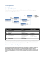
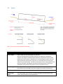
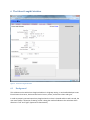
User Manual Rivergreen Enterprises September 5, 2012 Contents 1. Introduction .......................................................................................................................................... 3 1.1 General .......................................................................................................................................... 3 1.2 Signing Up ..................................................................................................................................... 3 1.3 Running CulvertPro ....................................................................................................................... 3 1.4 Pop‐Up Windows .......................................................................................................................... 3 2. Getting Started ...................................................................................................................................... 5 2.1 The Design Process ....................................................................................................................... 5 2.2 External Information Required ..................................................................................................... 5 3. The Culvert Hydraulics Calculator ......................................................................................................... 7 3.1 Background ................................................................................................................................... 7 3.2 Inputs ............................................................................................................................................ 8 3.3 Results ........................................................................................................................................... 9 3.4 Information Panel ....................................................................................................................... 10 4. The Rational Method Calculator ......................................................................................................... 11 4.1 Background ................................................................................................................................. 11 4.2 Inputs .......................................................................................................................................... 12 4.3 Results ......................................................................................................................................... 12 4.4 Information Panel ....................................................................................................................... 12 5 The SCS Method Calculator ................................................................................................................. 13 5.1 Background ................................................................................................................................. 13 5.2 Inputs .......................................................................................................................................... 14 5.3 Results ......................................................................................................................................... 14 5.4 Information Panel ....................................................................................................................... 15 6 The Culvert Length Calculator ............................................................................................................. 16 6.1 Background ................................................................................................................................. 16 6.2 Inputs .......................................................................................................................................... 17 6.3 Results ......................................................................................................................................... 18 7 The Tailwater Calculator ..................................................................................................................... 19 7.1 Background ................................................................................................................................. 19 7.2 Inputs .......................................................................................................................................... 20 7.3 Results ......................................................................................................................................... 20 7.4 Information Panel ....................................................................................................................... 20 1. Introduction 1.1 General CulvertPro is an internet based app that is intended for use by engineering professionals in the design of engineered culvert structures. It runs in your browser and the calculations are done on a server. It is accessible from www.culvertdesign.com or www.culvertpro.com. CulvertPro contains the following calculators: 1.2 Culvert Hydraulics Rational Method SCS Method Culvert Length Tailwater SigningUp To sign up for CulvertPro, simply point your browser to www.culvertdesign.com and click on ‘Sign Up’ on the right sidebar. Follow the prompts to enter your login credentials and billing information. 1.3 RunningCulvertPro Once signed up, the application is executed by pointing your browser to www.culvertdesign.com. From any page on the site, the login box will appear on the right sidebar. Enter your login credentials to access the application. 1.4 Pop‐UpWindows Please note that you must enable pop‐up windows on the site to allow CulvertPro to load. Due to ease of use (to keep the vast array of diverse background information out of the way of the simplified interface) we have designed CulvertPro with pop‐ups for the background information. For Microsoft Internet Explorer, go to Tools > Internet Options > Privacy > Pop‐up Blocker > Settings. For Mozilla Firefox, go to Firefox > Options > Content > Block Pop‐up Windows > Exceptions. For Google Chrome, choose Tools > Settings > Privacy > Content Settings > Pop‐ups > Manage Exceptions. Figure 1: The CulvertPro main screen 2. GettingStarted 2.1 TheDesignProcess If starting from scratch with no other sources of information, the order of calculators to proceed through a culvert design project is as follows: Order Calculator Result Required Inputs 1 Rational Method Design Flow 2 SCS Method Design Flow 3 Tailwater Tailwater Elevation Design Flow 4 Culvert Hydraulics Headwater Elevation Inlet and Outlet Velocities Design Flow Tailwater Elevation 5 Culvert Length Culvert Length The Time of Concentration of the watershed is an input into the Rational Method and SCS Method, but there is no stand‐alone calculator for it. Rather, it is found as a “background information” calculator in the Information Panel for both the Rational and SCS Methods. 2.2 ExternalInformationRequired The only external information generally required is basic rainfall data for the site, which is used by the Rational Method and SCS Method Calculators. This should be obtained in the form of Intensity‐ Duration‐Frequency (IDF) curves, which are available in most jurisdictions throughout the world. If IDF curves have not been produced for your area, a similar topographic region can be used to estimate the rainfall. In order to use the IDF data, the designer must choose a return period. In the United States, 1:100 year return periods are common for important infrastructure such as ports and major highways. On the other extreme, local roads and rural, low use infrastructure is often designed for 1:25 year return periods. Once the return period is chosen, the IDF curves show the designer what the rainfall statistics are under that return period. A single line will indicate the relationship of rainfall intensity with rainfall duration. The designer should experiment with different storm durations, but generally the storm duration corresponding to the time of concentration of the watershed defines the “correct” design rainfall event. 3. TheCulvertHydraulicsCalculator Figure 2: The Culvert Hydraulics Calculator 3.1 Background Culvert hydraulics calculations are based on the Federal Highway Administration’s (FHWA) Hydraulics Design Series #5 (HDS‐5) algorithms. In full flow conditions, headwater elevations and inlet/outlet velocities are determined by the greater of inlet control conditions and outlet control conditions. Under inlet control conditions, the culvert is assumed to be first an orifice (when flowing full) and then a weir (when not flowing full). The calculations are performed for each, and a sufficient interpolation is derived for the area between. Based on the tailwater specified, the appropriate headwater is obtained. Under outlet control conditions, the headwater is calculated directly using an energy balance equation. Losses are calculated at the inlet, barrel and outlet and the results are summed to obtain the total head loss. 3.2 Inputs Red = Inputs to the Culvert Hydraulics Calculator Input Description Culvert Shape Either round, box, horizontal ellipse, or pipe arch. We have included horizontal ellipse and pipe arch shapes for convenience, however the designer should be aware that there are problems with structure definition for these shapes. Manufacturers normally design the plate sizes and radii manually for each project, and there is no calculator that can universally define every possible shape. CulvertPro attempts to put the shape together with the given variables, but designers should use the Shape Selector Tool (in the Information Panel) whenever possible as this uses predefined sizes. Culvert Length The length of the culvert, in feet or metres. This value has very little effect on the result and can be estimated if the culvert length has not been calculated yet. Flow The flow to analyze through the culvert, in ft3/s or m3/s Channel Flow Depth The natural depth of the channel, averaged through the localized area of the culvert and measured from the lowest point. Upstream Invert Elevation The elevation of the upstream invert (feet or metres). Downstream Invert Elevation The elevation of the downstream invert (feet or metres). Manning’s n of Culvert Manning’s roughness value for the culvert. This varies based on corrugation profile (for corrugated steel), type of material, and any other factor that introduces “roughness” to the edge of the culvert which contacts water flow. A table of manning’s n values for commonly used culverts is included in the Information Panel Entrance Loss Coefficient Entrance losses are determined by the type of inlet. Entrance loss coefficients for common inlet conditions are included in the Information Panel. End Section The type of end section is used to calculate the exit loss coefficient (Ke). 3.3 Square Edge w/Headwall: The culvert contains a vertical wall (headwall) around its ends. Conforming to slope: The culvert end is sloped or bevelled to conform to a road or other embankment. Projecting from Slope: The culvert ends are vertical (uncut) and the invert elevation matches the slope of the embankment, therefore the culvert projects from the fill. Results CulvertPro’s Hydraulic calculator will produce the following results: Headwater The elevation of the water above the culvert inlet. This is a common design variable. Typical values are the culvert crown or road elevation. Some jurisdictions specify a certain height above the culvert crown. Local infrastructure which requires protection from flooding should be surveyed to ensure it is not below this headwater. Upstream Velocity The localized extreme velocity at the upstream end of the culvert. Downstream Velocity The localized extreme velocity at the downstream end of the culvert. Flow Profile FF: Full Flow. M1: Mild slope. Slope is greater than normal depth. M2t: Mild slope. Slope is greater than critical depth but less than normal depth. M2c: Mild slope. Slope is less than critical depth. S1f: Steep slope. Tailwater is above the culvert crown. S1t: Steep slope. Tailwater is above normal depth. S2n: Steep slope. Tailwater is below normal depth and flow is assumed at critical depth on the upstream end. Normal Depth The depth of flow when outside the influence of inlet and outlet tailwater. Normal depth occurs when gravitational force of the water is equal to the friction drag along the culvert and there is no acceleration of flow. Critical Depth 3.4 The depth of flow in which the specific energy is a minimum. Also, it is the boundary between supercritical and subcritical flow. InformationPanel The following items are contained in the Culvert Hydraulics Information Panel: Shape Selector Tool This handy tool assists with choosing shapes and sizes. Any shape and size on this list will be specifiable without any problems as they have been taken from industry‐published shape tables. It is not, however, a comprehensive list as manufacturers can create customized shapes and sizes to suit any project. Manning’s n Table A table of manning’s roughness values for culvert types, to assist with the “Manning’s n of Culvert” input. Entrance Loss Coefficients A table of entrance loss coefficients related to culvert inlet types, to assist with the “Entrance Loss Coefficient” input. Normally jurisdictions have design criteria which include one of more of the following: 1. Headwater Elevation (eg. Lower than culvert crown or any surrounding buildings) 2. Velocities (eg. No more than twice the normal channel velocity on each end) 3. Head losses (eg. Maximum head loss) 4. TheRationalMethodCalculator Figure 3: The Rational Method Calculator 4.1 Background The rational method calculator presents a simple, intuitive, and quick method of determining design flows at a site. The formula is as follows: Where: Q = Runoff (ft3/s or m3/s) k = is the constant 0.00278 for metric and 1.0 for U.S. units C = runoff coefficient i = rainfall intensity (in/hr or mm/hr) A = drainage area (hectares) The Rational Method makes the following assumptions: The rainfall intensity is uniform over the entire watershed during the entire storm duration. The rainfall lasts at least as long as the time of concentration of the watershed. Because of these assumptions, care should be taken in the selection of the runoff coefficient, C. This coefficient takes into account all the hydrological abstractions, soil types and antecedent conditions, and its selection has a direct impact on the result. 4.2 Inputs Input Description Runoff Coefficient The runoff coefficient, C. Rainfall Intensity The intensity of the rainfall assumed to occur over the entire drainage basin for at least the time of concentration, in inches/hour, or millimetres/hour. Drainage Area The drainage area, in square miles or square kilometres. Most representations of the rational method formula use hectares, however CulvertPro uses square miles or square kilometres for ease of use. 4.3 Results CulvertPro’s Rational Method calculator produces the following result: Peak Discharge 4.4 The runoff, Q, at the site in question, in ft3/s or m3/s InformationPanel The following items are contained in the Rational Method Information Panel: C Table A table of runoff coefficients for common drainage basin characteristics, to assist with the input “Runoff Coefficient.” View Drainage Area in Google Maps To assist in choosing a runoff coefficient, CulvertPro contains this handy feature. Google Maps’ satellite view shows you how wooded or treed a basin is (among other things), and the topographic map shows you the relief. Hybrid Runoff Coefficient Calculator When different areas of the drainage basin have different characteristics, you can assign multiple runoff coefficients and scale the final value to the respective areas. Time of Concentration Calculator The rainfall intensity (i) should be such that it will occur over the entire drainage area for at least the amount of time it takes for the furthest drop of water in the drainage area to reach the site. This time frame is defined as the time of concentration of the watershed, and this handy calculator uses the three most commonly used methods. USGS Topographic Maps Since you will want to see some topographic maps, if you don’t already have them, we have included the link to the American ones right in the software. 5 TheSCSMethodCalculator Figure 4: The SCS Method Calculator 5.1 Background To account for the potential storage of rainfall in the soil, the Natural Resources Conservation Service (NRCS) developed the SCS Method for determining the runoff of a watershed. It is named after the agencies former name, the Soil Conservation Service. In this method, the runoff rate is calculated as follows: 484 0.5 0.6 Where: qp = Runoff (ft3/s or m3/s). A = Drainage area (square miles or square kilometres). Q = Depth of runoff (inches or millimetres). See below. D = Duration of rainfall (hours). tc = Time of concentration (hours). See below. The depth of runoff is determined based on the retention of the initial rainfall within the soil: 0.2 0.8 Where: Q = the depth of runoff (inches or millimetres). P = Cumulative rainfall depth, intensity x duration (inches or millimetres). S = Potential retention (inches or millimetres). See below. A theoretical triangular hydrograph is assumed with the following time to peak: 1000 Where: 5.2 10 S = Potential retention (inches or millimetres) CN = Curve Number. Looked up from published tables. Inputs Input Description Drainage Area The drainage area, in square miles or square kilometres. Curve Number This value is looked up on tables (included in the Information Panel). The curve number defines the soil, cover, and hydrologic conditions of the land surface. They are based on four soil types: Group A: High infiltration (low runoff). Sand, loamy sand, or sandy loam. Infiltration rate > 0.3 in./hr when wet. Group B: Moderate infiltration (moderate runoff). Silt loam or loam. Infiltration rate 0.15 to 0.3 in./hr when wet. Group C: Low infiltration (moderate to high runoff). Sandy clay loam. Infiltration rate 0.05 to 0.15 in./hr when wet. Group D: Very low infiltration (high runoff). Clay loam, silty clay loam, sandy clay, silty clay, or clay. Infiltration rate 0 to 0.05 in./hr when wet. Time of Concentration The amount of time it takes for the furthest drop of water in the drainage area to reach the site. The handy calculator in the Information Panel utilizes the three most commonly used methods. Rainfall Intensity The intensity of the design storm, in inches/hour or millimetres/hour. Rainfall Duration The duration of the design storm, in hours. Together with the rainfall intensity, this will define a theoretical storm. The SCS method assumes a storm of this intensity and magnitude, and calculates a theoretical triangular runoff hydrograph. 5.3 Results CulvertPro’s SCS Method calculator produces the following result: Peak Discharge The runoff, Q, at the site, in ft3/s or m3/s Viewing the report will show the intermediate variables Q (runoff depth) and S (potential retention) 5.4 InformationPanel The following items are contained in the SCS Method Information Panel: CN Table A table of curve numbers and soil type descriptions, to assist with the input “Curve Number.” Hybrid Curve Number When different areas of the drainage basin have different characteristics, you Calculator can assign multiple curve numbers and scale the final value to the respective areas. View Drainage Area in Google Maps To assist in choosing a curve number, CulvertPro contains this handy feature. Google Maps’ satellite view shows you how wooded or treed a basin is (among other things), and the topographic map shows you the relief. Time of Concentration Calculator This handy calculator utilizes the three most commonly used methods to help you determine the time of concentration of the watershed, which is defined as the time it takes for the furthest drop of water in the drainage area to reach the site. USGS Topographic Maps Since you will want to see some topographic maps, if you don’t already have them, we have included the link to the American ones right in the software. 6 TheCulvertLengthCalculator Figure 5: The Culvert Length Calculator 6.1 Background This calculator assists with culvert length calculation in a highway setting. It can handle sideslope issues like minimum clear zones, horizontal and vertical curves, skews, and various culvert end types. In order to properly communicate culvert lengths when the culvert is skewed and the road is curved, the user must choose a “direction of viewing” which is along the road and indicate to the calculator which direction is “left” and “right” (upstream or downstream). 6.2 Inputs Input Description Culvert Rise The vertical dimension of the culvert, in inches or metres Invert Elevation at Road CL The invert elevation of the culvert at the road centerline. If the culvert is cambered, using the straight‐line elevation between the inverts will still produce an accurate result. Gradient The slope of the culvert, in ft/ft or m/m. Downstream The direction which is downstream. The user must choose a “direction of viewing” which is along the road in either direction, and indicate which direction is downstream. Skew The degree of skew of the culvert Skew Direction The direction of skew. Based on the direction of viewing (see “Downstream” above) this value is either Left Hand Forward (LHF) or Right Hand Forward (RHF). End Section The type of end section of the culvert and how the sideslope ties in to it. Possible values: Straight End: The culvert has a vertical (uncut) end and the sideslope ties in to the bottom edge. Full Bevel: The culvert has a sloped end conforming to the road slope. The user must input: o Bevel Length: The horizontal length of the sloped end. o Road slope tie‐in point: Either at the top or the bottom of the bevelled end. Step Bevel: Used in many jurisdictions, the “step bevelled” culvert has a sloped end with two vertical “steps” at the top and bottom of the sloped end. The required inputs are: o Step Height: Both steps require the same height. o Step Length: The length of the sloped section. o Road slope tie‐in point: The road slope can tie‐in to the top edge of the top step, the bottom of the top step, the top of the bottom step, or the bottom of the bottom step. Road Width The design width of the roadway, in feet or metres. Crown The crown of the roadway. Sideslope The sideslope of the roadway. Sideslope Criteria None: The sideslope is calculated down the specified road slope tie‐in point. Minimum Clear Zone: Use this is you would like to leave the top of the culvert a certain “clear distance” from the road shoulder. You will need to enter the clear distance and the maximum slope within that clear zone (if you would like to keep a different maximum). If the culvert length is greater than the clear zone due to other factors, the calculator will create a “broken back” slope using the maximum slope within the clear zone and Culvert Road Station road sideslope (entered above) below the clear zone. Benched: If you need to have a bench within the sideslope, use this option. You will need to enter the bench width and the vertical distance below the road shoulder. Used for vertical and horizontal alignments, this is the road station of the centerline of the culvert. Vertical Alignment Either flat, grade, or vertical curve. Horizontal Alignment 6.3 Flat. Enter the road elevation. Grade. Enter a point anywhere on the gradeline, defined by the point’s station, elevation, and grade. Vertical Curve. Enter the stations and elevations of the three points defining the curve, the Point of Vertical Curvature (PVC), Point of Vertical Inflection (PVI) and Point of Vertical Tangency (PVT). These are also known by the terms Beginning of Vertical Curvature (BVC), Point of Inflection (PI) and End of Vertical Curvature (EVC). Either straight or curved Straight. There are no more inputs. Curved. Enter the direction of the curve (corresponding to the “viewing direction” defined above), the curve radius, and the superelevation. This superelevation will be used across the entire roadway – currently CulvertPro cannot compute transition zones. Results CulvertPro’s length calculator produces the following results: Culvert Length The required length of culvert given all of the inputs Square Length The length of the culvert on square to the roadway (i.e. non‐skewed length). This number is often put on design drawings. Upstream, skewed The skewed length on the upstream side of the road centerline. Upstream, square The square length on the upstream side of the road centerline. Downstream, skewed The skewed length on the downstream side of the road centerline. Downstream, square The square length of the downstream side of the road centerline. 7 TheTailwaterCalculator Figure 6: The Tailwater Calculator 7.1 Background The tailwater calculator assists in the calculation of the “Channel Flow Depth” value in the Culvert Hydraulics calculator. The user must assume certain channel cross section parameters, and the calculator uses manning’s equation to determine a flow depth. Manning’s equation is as follows: Where: Q = Flow (ft3/s or m3/s) A = Cross‐sectional area of flow, in ft2 or m2 R = Hydraulic radius = Area/Wetted Perimeter, in feet or metres S = Slope of channel, in feet/foot or metres/metre n = Manning’s roughness coefficient 7.2 Inputs Input Description Flow The flow in the channel, in ft3/s or m3/s Channel Slope The slope of the channel, in ft/ft or m/m Manning’s n The manning roughness coefficient of the channel Channel Shape The calculator can compute rectangular, triangular, and trapezoidal channels 7.3 Rectangular: Enter the channel bottom width and channel depth Triangular: Enter the channel sideslope and depth. Trapezoidal: Enter the channel bottom width, channel sideslope and channel depth. Results CulvertPro’s tailwater calculator produces the following result: Channel Flow Depth The depth of flow in the channel, in feet or metres Channel Velocity The velocity of the flow in the channel as defined, in ft/s or m/s 7.4 InformationPanel The following items are contained in the Culvert Hydraulics Information Panel: Manning’s n Table A table of manning’s roughness coefficients for typical channel conditions, to assist with the input “Manning’s n.”