1
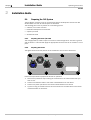
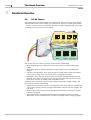
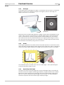
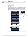
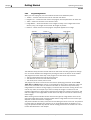
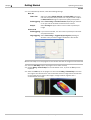
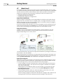
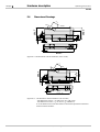
Operating instructions Industrial Vision Camera IVC-3D A calibrated smart camera for 3D measurements Please read the complete manual before attempting to operate your IVC-3D. WARNING This product is equipped with a Class 2M laser according to EC 60825-1 or Class II according to 21 CFR 1040.10 / 11 (CDRH), respectively. Class 2M lasers emit visible radiation in the wavelength range from 400 nm to 700 nm where eye protection is normally afforded by aversion responses including the blink reflex. However, viewing of the output is hazardous if the user employs optical instruments within the beam or suppresses the blink reflex intentionally. LASER RADIATION – DO NOT STARE INTO BEAM OR VIEW DIRECTLY WITH OPTICAL INSTRUMENTS CLASS 2M LASER PRODUCT according to IEC 60825-1 : 2001-8 Do not stare into beam. Do not view the laser beam directly with optical instruments like magnifying glasses, telescopes, etc. The IVC-3D is a laser product and operation using procedures other than those specified herein may result in hazardous radiation exposure. Do not open the IVC-3D The IVC-3D unit should not be opened, the IVC-3D contains no user serviceable parts inside. Opening the IVC-3D unit may result in hazardous radiation exposure. Turn off the power to the IVC-3D before maintenance The power to the IVC-3D must be turned off before any maintenance is performed. Failure to turn this power off when maintaining the unit may result in hazardous radiation exposure. ISM Radio Frequency Classification - EN55011 – Group1, Class A Warning: Class A equipment is intended for use in an industrial environment. There may be potential difficulties in ensuring electromagnetic compatibility in other environments, due to conducted as well as radiated disturbances. Explanations: Group1 – ISM equipment (ISM = Industrial, Scientific and Medical) Group 1 contains all ISM equipment in which there is intentionally generated and/or used conductively coupled radio-frequency energy which is necessary for the internal functioning of the equipment itself. Class A equipment is equipment suitable for use in all establishments other than domestic and those directly connected to a low voltage power supply network which supplies buildings used for domestic purposes. Class A equipment shall meet class A limits. Note: Although class A limits have been derived for industrial and commercial establishments, administrations may allow, with whatever additional measures are necessary, the installation and use of class A ISM equipment in a domestic establishment or in an establishment connected directly to domestic electricity power supplies. Please read and follow ALL Warning statements throughout this manual. German versions of the Operating Instructions and Reference manual are available on the CD. Eine deutsche Version der Bedienungsanleitung und des Referenzhandbuchs finden Sie auf der beigelegten CD. © SICK IVP 2006-11-24 All rights reserved 8011007 Subject to change without prior notice. Operating Instructions Contents IVC-3D Contents 1 Introduction............................................................................................................................................................5 1.1 2 Installation Guide .................................................................................................................................................6 2.1 2.2 2.3 3 3.1 IVC-3D Camera ......................................................................................................................... 10 3.1.1 3D Images................................................................................................................... 11 3.1.2 Profiles ........................................................................................................................ 11 3.1.3 Suppressing ambient light......................................................................................... 11 3.1.4 Capturing 3D Images ................................................................................................. 12 3.1.5 Missing Data............................................................................................................... 12 3.2 IVC Studio.................................................................................................................................. 13 3.2.1 Programs in Development and Production.............................................................. 13 3.2.2 Saving Programs ........................................................................................................ 14 Handling Multiple Products ..................................................................................................... 15 Getting Started .................................................................................................................................................. 16 4.1 4.2 4.3 4.4 4.5 4.6 4.7 5 Creating a Product ................................................................................................................... 16 4.1.1 Create a Product ........................................................................................................ 17 4.1.2 Select a Device........................................................................................................... 18 4.1.3 Create a Program ....................................................................................................... 18 4.1.4 Create a Table ............................................................................................................ 18 About Writing Programs........................................................................................................... 19 4.2.1 Tools ............................................................................................................................ 19 4.2.2 Programming Window................................................................................................ 20 Adding Program Steps ............................................................................................................. 21 Setting Parameter Values........................................................................................................ 24 4.4.1 Setting Constant Parameter Values ......................................................................... 24 4.4.2 Using Tables and Results from Other Steps ............................................................ 26 4.4.3 Setting Parameter Values with Expressions ............................................................ 28 4.4.4 Using Conditions and Jumps ..................................................................................... 28 Testing and Running the Program .......................................................................................... 30 Saving the Program.................................................................................................................. 31 What’s Next?............................................................................................................................. 32 Hardware description....................................................................................................................................... 33 5.1 5.2 5.3 5.4 8011007 Preparing the IVC System ...........................................................................................................6 2.1.1 Preparing the Power I/O Cable ....................................................................................6 2.1.2 Preparing the Device.....................................................................................................6 Installing IVC Studio ....................................................................................................................7 Receiving an Image from the Device.........................................................................................7 Functional Overview ......................................................................................................................................... 10 3.3 4 Laser Safety .................................................................................................................................5 Measurement setup................................................................................................................. 33 Electrical Connections ............................................................................................................. 34 Technical Data.......................................................................................................................... 37 Dimensional Drawings ............................................................................................................. 38 SICK IVP • Industrial Sensors • www.sickivp.com • All rights reserved 3 Operating Instructions IVC-3D 4 SICK IVP • Industrial Sensors • www.sickivp.com • All rights reserved 8011007 Operating Instructions Introduction Chapter 1 IVC-3D 1 Introduction The IVC-3D is a Smart Camera that combines imaging and analysis into one camera housing. The camera performs inspection, location or measurement of objects in order to enhance production yield, control production or perform quality control. When your application needs measurement or verification of non-flat dimensions, a smart camera that highlights height differences in the captured images is preferable compared to traditional two dimensional imaging. The IVC-3D is a smart camera in every aspect such as easy configuration via a pc user interface, a set of image processing tools generally applicable to your application, easy connection to I/O as well as serial and Ethernet communication. The IVC-3D has a major advantage – it can see three dimensions. Highlighting surface defects depending on topography is now already done in the image capturing. With tools that are defined to measure heights, volume, shapes etc previously tricky measurement tasks now are easily solved with the calibrated 3D smart camera. 1.1 Laser Safety This product is equipped with a Class 2M laser according to EC 60825-1 or Class II according to 21 CFR 1040.10 / 11 (CDRH), respectively. Class 2M lasers emit visible radiation in the wavelength range from 400 nm to 700 nm where eye protection is normally afforded by aversion responses including the blink reflex. However, viewing of the output is hazardous if the user employs optical instruments within the beam or suppresses the blink reflex intentionally. Do not stare into beam. Do not view the laser beam directly with optical instruments like magnifying glasses, telescopes, etc. LASER RADIATION – DO NOT STARE INTO BEAM OR VIEW DIRECTLY WITH OPTICAL INSTRUMENTS CLASS 2M LASER PRODUCT according to IEC 60825-1 : 2001-8 8011007 SICK IVP • Industrial Sensors • www.sickivp.com • All rights reserved 5 Chapter 2 Installation Guide Operating Instructions IVC-3D 2 Installation Guide 2.1 Preparing the IVC System The IVC System consists of one or more devices and the development environment IVC Studio. Make sure that all ordered parts are delivered. The following parts must be present in a functioning system: A device, in this case a camera IVC Studio development environment A power I/O cable An Ethernet cable 2.1.1 Preparing the Power I/O Cable The orange power I/O cable is open in one end. It contains eight wires. The blue is ground and the brown is +24 volts DC. Apply an appropriate connector but do not connect it at this point. 2.1.2 Preparing the Device The figure below shows the position of the connectors on the back of the device. link data ON function RS485 Ethernet power encoder Follow the steps below to prepare the device for operation. 1. Remove the protection caps covering the connection for the cable sockets that you want to use. 2. Connect the Ethernet cable to the socket marked Ethernet on the device. 3. Connect the power I/O cable to the socket marked Power on the device. 4. If you are using an encoder with the camera connect the encoder cable to the socket marked Encoder on the device. 6 SICK IVP • Industrial Sensors • www.sickivp.com • All rights reserved 8011007 Operating Instructions Installation Guide Chapter 2 IVC-3D 2.2 Installing IVC Studio To install IVC Studio, insert the CD in the PC and go through the Setup Wizard. When the installation is completed you may have to restart the PC. The first time you open IVC Studio you are first prompted to enter a company name and serial code. The serial code is found in the file serial.txt, located in the same folder as IVC Studio. You are then prompted for a user name and password. The following user and password can currently be used: User name Password Administrator admin Operator operator By default you only have to log in the first time you start IVC Studio. If you want the users to log in every time they start IVC Studio, choose Options Æ Configuration from the IVC Studio menu bar, select User Access and change the setting. 2.3 Receiving an Image from the Device The device must have an IP address in order to communicate with the PC over Ethernet. The way to provide the IP address depends on how the device is connected to the PC. The three typical options are: The device is connected through a switch to a network with a DHCP server. In this case the device will automatically get a dynamic IP address. This is the default setting. The device is connected through a switch to a network without a DHCP server. In this case a network technician provides an unoccupied IP address. The device is connected directly to the PC either through a switch or a cross-over Ethernet cable. In this case the IP address of the device should use the same sub-net as the PC. The PC IP address is shown in the device configuration window as local IP address. At delivery the IP parameters of the device are configured as follows: IP 0.0.0.0 Netmask 0.0.0.0 Gateway 0.0.0.0 DNS 0.0.0.0 WINS 0.0.0.0 TimeServer 0.0.0.0 DHCP 1 DHCP Wait Save 5 DHCP IP AutoConfiguration 1 8011007 SICK IVP • Industrial Sensors • www.sickivp.com • All rights reserved 7 Chapter 2 Installation Guide Operating Instructions IVC-3D Follow the steps below to receive an image from the device. 5. Make sure the PC is connected to a server or a switch and connect the Ethernet cable from the device to the same network server or switch as the PC. If you connect the device directly to the PC make sure you use a crossover Ethernet cable. 6. Connect the power I/O cable to +24 volts and GND. 7. Start IVC Studio. If you start IVC Studio for the first time, enter a company name and the serial number, and log in as administrator. 8. Choose File Æ Open Product... and open the product Empty.prd. 9. Click Devices in the left pane in the main window. If you are connected to a network with a DHCP server, the device should be displayed in the right pane. If the device is running a program (STATUS: RUN), stop the program by right-clicking the device in the right pane and choose Stop Program. Choose Options Æ Configuration from the IVC Studio menu bar. Select Ethernet Devices in the dialog box and click Ethernet Devices Configuration. A list of all connected devices appears. Select the device. All available settings appear in the right pane. Make the necessary settings, depending on your connection method: 10. 11. 12. 13. Connection method Through a switch to a network with a DHCP server Through a switch to a network without a DHCP server Parameter ID IP ID Netmask DHCP If there are subnets in the network, the IP address of your network’s gateway. This should be provided by a network technician. Set to 0 (zero). DHCP IPAutoConfiguration Set to 0 (zero). IP ID Netmask DHCP DHCP IPAutoConfiguration All settings are the same as for a network without DHCP server (above). The IP address of the device should use the same subnet as the PC. Gateway Directly to the PC either through a switch or a crossover Ethernet cable Value Set to the customer serial number or another number that is unique in the network. An unoccupied IP address, provided by a network technician. Set to the customer serial number or another number that is unique in the network. Your network’s netmask, provided by a network technician. See appendix B of the IVC-3D Reference Manual for detailed information on the parameters. 8 SICK IVP • Industrial Sensors • www.sickivp.com • All rights reserved 8011007 Operating Instructions Installation Guide Chapter 2 IVC-3D 14. Save the settings and close all dialog boxes. 15. Choose Options Æ Configuration or press Ctrl-F5 until the device appears in the device list. This will search the network for available devices. 16. Right-click the device in the right pane and choose Select Program. In the dialog box, select the program Empty and click OK. 17. Right-click the device in the right pane and choose Select Table. In the dialog box, select the program EmptyTable and click OK. 18. Click Programs in the left pane in the main window, and select the program Empty. The program list, image banks and tools toolbar are displayed in the right pane. 19. Click on the Grab setup tool (on the Image tab in the toolbar). The Grab setup tool is added to the program list. 20. Double-click the Setup button on the program step in the program list. The Grab setup dialog box is displayed. 21. Aim the device at a suitable target, and adjust the field of view until you can see the profile of the target in the preview. 8011007 SICK IVP • Industrial Sensors • www.sickivp.com • All rights reserved 9 Chapter 3 Functional Overview Operating Instructions IVC-3D 3 Functional Overview 3.1 IVC-3D Camera The IVC-3D camera contains a powerful microprocessor that is tailored for image analysis and especially analysis of 3D images. The processor can perform a number of commands – or tools – that are used for example for capturing an image, finding an edge in an image or setting one of the camera’s output signals. Working Memory x1=1.273 y1=9.742 z1=6.37 ... Active Program Active Table Image Banks Data Blocks Flash Memory 1 1 1 2 2 2 3 3 4 4 3 4 5 5 5 ... ... ... Program Banks Saved Images Saved Data Blocks The camera also has a working memory, which contains the following: Active program, which is a sequence of commands that are used for analyzing the images. Active table, which is used for reading and storing values that are used during the analysis. A number of image banks, which each contains an image captured and processed by the camera. An image bank may contain either a 3D image or a profile. Data blocks, which are used by some tools for storing or reading additional data. For example, some pattern recognition tools (Teach tools) create and save data in a data block, which can later be used by other tools (Match tools). In addition, the camera has a flash memory, which is used for permanent storage. The flash memory contains the following: Program banks, which are used for storing programs and tables that can be loaded into the camera’s working memory. A program bank always contains both one program and one table. Saved images, which can be used for example as a basis when teaching the camera patterns to recognize. Saved data blocks, containing for example pattern recognition data to be used by Match tools, so that the pattern does not have to be taught before running a program. 10 SICK IVP • Industrial Sensors • www.sickivp.com • All rights reserved 8011007 Operating Instructions Functional Overview Chapter 3 IVC-3D 3.1.1 3D Images A 3D image shows the topology of an object, or the distance from the bottom (or reference plane) to a point on the surface of the object. The brighter a pixel is in the image, the higher up that point is on the object. x (width) z (height) y (transport) x (width) y (transport) Since each pixel in the 3D image represents a height the pixel values are displayed in millimeters, and not as gray or color values as in ordinary digital images. The resulting height value is measured from a reference plane located at a fixed distance from the camera. This means that the units of the 3D coordinates in an image are pixels along the x- and yaxis, and millimeters along the z-axis. The coordinates in the 3D image can however easily be converted to millimeters by using a tool in the camera. 3.1.2 Profiles A 3D image is generated from profiles, where each profile represents a cross-section of the object. A profile is created when the object passes under a laser beam, which is reflected as a line on the object. When viewed from an angle, the line shows the contour of the object. z Profile x The coordinate system in profiles is the same as in 3D images – that is pixels along the x-axis and millimeters along the z-axis. 3.1.3 Suppressing ambient light The laser line used to create 3D images has a certain wavelength range, and the IVC-3D has built-in filters that suppress ambient light. However, sunlight and also some standard light sources used at factory floors contain light with the same wavelength range as the laser. For a robust measurement day and night, all over the year, it is recommended to shroud the inspection area from ambient light, especially sunlight. 8011007 SICK IVP • Industrial Sensors • www.sickivp.com • All rights reserved 11 Chapter 3 Functional Overview Operating Instructions IVC-3D 3.1.4 Capturing 3D Images The camera takes a suitable number of profiles as the object passes under the laser. By knowing the distance that the object moved between two profiles the camera can build a 3D image of the object from the profiles. The camera assumes that the distance between the profiles is constant. Therefore it is important to make sure that this is actually the case, in order to generate accurate 3D images. There are two ways to achieve this: • Make sure that the object is moving with a known and constant speed. The speed is specified in the program, and the camera will then take profiles with a constant time interval. • Use an encoder. In this case, the encoder will trigger the camera to take a profile when the object has moved a certain distance. It is strongly recommended to use an encoder if you intend to measure for example the shape or volume of the objects. If no encoder is used, the results of the analysis may be inaccurate if the speed of the objects varies. Object is moving with the expected speed 3.1.5 Object is moving slower than expected The speed of the object is uneven Missing Data Sometimes the laser line on the object is hidden by other parts of the object. This makes it impossible for the camera to decide the height of the part of the object that is obscured. In the resulting 3D image, such areas are represented with missing data, which is displayed as black or holes when viewing the image. z Profile Profile is missing x Normally, the tools that are used for analyzing the 3D images ignore missing data. However, some tools treat missing data as a height value of 0 mm. This may affect the result of the analysis, for example an edge could be detected at a location in the image where there are actually missing data. A list of those tools is found in appendix C in the reference manual. The camera has a tool for removing missing data from an image and thereby minimizing the impact on the analysis made by such tools. The Fill Missing Data tool assumes that the height of the hidden area is same as the area surrounding it, and thus “fills in the hole”. 12 SICK IVP • Industrial Sensors • www.sickivp.com • All rights reserved 8011007 Operating Instructions Functional Overview Chapter 3 IVC-3D 3.2 IVC Studio IVC Studio is used for developing the programs that are used by the cameras when performing inspections – that is, analyzing images. IVC Studio can handle both 2D and 3D cameras. When you develop a program in IVC Studio, you work with a product. A product in IVC Studio is a great help for handling all the devices (usually cameras), programs and tables that are needed for a certain inspection. The product contains a list of the used devices, and copies of all programs and tables that are used by the devices. Normally, each device has one program and one table associated to it, which is also the program and table that are currently in the working memory. To be able to work with a program in IVC Studio, it must be associated with a device. A program is always executed on a device – and never on the computer. The computer is mainly used for building and modifying the programs on the devices, and to display the results sent from the devices. Product Devices Camera1 Camera2 << Programs 3.2.1 Camera3 uses >> Tables Label LabelTable FillLevel FillTable Programs in Development and Production During development, you build the program in IVC Studio but the program is automatically downloaded to the associated device. When a program (or program step) is executed it is executed in the camera, and the results are sent back to IVC Studio where they are displayed. Program steps Table values Images Result values 8011007 SICK IVP • Industrial Sensors • www.sickivp.com • All rights reserved 13 Chapter 3 Functional Overview Operating Instructions IVC-3D When the development of a program is finished and it is ready to be used, the program (and table) is downloaded to the device and started. After this it is not necessary to use IVC Studio any more. It may be used to display the results from the program, for example to signal when faults occur. But the device can also be used as a stand-alone unit, where other equipment is used for controlling the device and displaying the output. For example, you could set up a web page on the camera and then monitor the camera from a web browser on any computer on the network. Programs Tables Input Output 3.2.2 Saving Programs When you save a product in IVC Studio, the included programs and tables are saved with the product on the computer. Nothing is saved on the device when you save the product. This is not a problem since the program associated with the device is automatically loaded into the device as soon as the program is started or edited in IVC Studio. Product Copied automatically Devices Camera 1 Associated Program Working Memory Flash Memory Active Program 1 2 3 4 5 ... Camera 2 Associated Table Copy values manually Active Table Save in Flash Program Banks The programs and tables may be stored manually on the device as well. The flash memory in the device contains a number of program banks, each of which can contain a program and a table. When you store a program in the flash memory, you always store the active program and table, which are currently in the working memory of the device. A program stored in program bank 0 will automatically be started when the device is powered up. 14 SICK IVP • Industrial Sensors • www.sickivp.com • All rights reserved 8011007 Operating Instructions Functional Overview Chapter 3 IVC-3D 3.3 Handling Multiple Products A device may be used in several products, using different programs and tables depending on the product. This makes it easy to use the same camera for performing different inspections. Just create one product for each inspection, and in each product associate the program and table to be used for the specific inspection. For example, there are three cameras set up by a production line, and we are producing two different items on this production line – a transparent bottle and an opaque jar. For the bottle we can use IVC-2D cameras to inspect both the label on the front and the fill level, but for the jar we need to use an IVC-3D camera to inspect the fill level. Device 3 Device 2 Device 1 Device 1 Product: Bottle Dev Program 1 Label 2 Bottle_FillLevel Product: Jar Table Bottle_Label_Table Bottle_FillLevel_Table Dev Program 1 Label 3 Jar_FillLevel Table Jar_Label_Table Jar_FillLevel_Table To achieve this we create two products in IVC Studio with the following contents: Product: Bottle Device Program 1 Label 2 Bottle_FillLevel Table Bottle_Label_Table Bottle_FillLevel_Table Product: Jar Device Program 1 Label 3 Jar_FillLevel Table Jar_Label_Table Jar_FillLevel_Table When switching between producing the two products, we can simply open the product in IVC Studio to load the corresponding programs and tables into the devices. If we would change the design of the label for the bottle, we can just change the values in the table Bottle_Label_Table to suit the new design. If necessary we could also make a copy of the program Label, modify it, and associate the modified program with device 1. 8011007 SICK IVP • Industrial Sensors • www.sickivp.com • All rights reserved 15 Chapter 4 Getting Started Operating Instructions IVC-3D 4 Getting Started In this chapter we will introduce the basics in IVC Studio and learn how to: Create a product in IVC Studio in which to write the program Write the program - that is adding program steps and setting parameters Test and debug the program As an example we will build a simple program that slices a loaf of bread in a number of pieces of equal volume (or weight if we can assume that the density is constant). One way to achieve this is to: Capture a 3D image of the loaf Calculate the total volume of the loaf and divide that volume with the desired number of slices to get the volume of each slice Move along the 3D image from one end to the other, while calculating the accumulated volume of the part of the loaf that we have covered Scanning direction Slices Accumulated volume When the accumulated volume is equal to (or larger than) the desired volume of a slice, the current position is stored and the accumulated volume is reset. In a real production environment, the camera could control a knife that slices the loaf at the correct places. It is assumed that the camera and IVC Studio are installed and are working properly. How to install the camera and IVC Studio is described in the installation instruction. To capture 3D images you would also need movement and some kind of trigger for triggering the 3D image grab. It is also strongly recommended to use an encoder for capturing accurate 3D images. 4.1 Creating a Product Before starting to write the program, we need the following: A product to work with A device to use in the product (in this case a camera) A program written for the device A table used for the program in the device A product in IVC Studio is a collection of devices (usually cameras) that are used for performing an inspection, for example of loafs of bread on a production line. Each device contains one or more programs that instruct the device how to perform the inspection. 16 SICK IVP • Industrial Sensors • www.sickivp.com • All rights reserved 8011007 Operating Instructions Getting Started Chapter 4 IVC-3D A program is a list of commands, or tools, that the device executes one by one, in order to capture images, analyze them and draw conclusions from them. To its help, the program has a table that it can read values from and store results in. Product Devices Camera1 << Camera2 uses >> Programs 4.1.1 Camera3 Tables Label LabelTable FillLevel FillTable Create a Product The first step is to create the product to work with: 1. Start IVC Studio and log in. If you just installed IVC Studio, the default user and password can be found in the installation instruction. 2. Choose File Æ New Product from the IVC Studio menu bar. A new empty product named New Product is opened. The main window shows the contents of the currently open product. The left pane shows the different categories of objects that the product may contain, that is; devices, programs and tables. Clicking on one of the categories will display the objects contained in the product. Since the product was just created, all categories are empty, with the exception of Devices, which contains all devices that are available. Left pane Right pane There is also a fourth category that we haven’t mentioned yet - macros. Macros are basically small programs that you can call from within regular programs. They can be useful for reusing blocks of program steps when writing advanced programs. 8011007 SICK IVP • Industrial Sensors • www.sickivp.com • All rights reserved 17 Chapter 4 Getting Started Operating Instructions IVC-3D 4.1.2 Select a Device The next step is to select the device used for the inspection: 3. Click Devices in the left pane of the main window. The camera is displayed in the right pane. If there are more devices that can be used by IVC Studio in your network, those will also be displayed there. 4. Select a device by clicking in the checkbox in front of it in the right pane. You should always select the devices that you intend to use in your product. IVC Studio periodically updates the information in the device list by polling the devices that are selected in the list. If no device is selected in the list, IVC Studio will poll every device it can find for information. This slows IVC Studio down and may also affect the performance of devices used in other applications. 4.1.3 Create a Program We are now ready to create the program we intend to build and to associate it with a device. The reason for associating the program with a device before building it is that the program is always run on a device and not on the computer. What you see in IVC Studio when running a program are just the results, which are sent from the device. If you did not associate the program with a device, you would not be able to see any result of the program or even test the program. 5. Right-click Programs in the left pane of the main window and choose New Program from the pop-up menu. 6. Fill in a name for the program in the dialog box and click OK. 7. Click Devices in the left pane of the main window. 8. In the right pane, right-click the device that is selected for the product and choose Select Program from the pop-up menu. 9. Select the program in the list in the dialog box and click OK. 4.1.4 Create a Table There must also be a table associated with the device, so before starting to build the program we must create a table and associate it with the device: 10. Create the table by right-clicking Tables in the left pane, choosing New Table from the pop-up menu and filling in a name in the dialog box. 11. Right-click the device that is selected for the product and choose Select Table from the pop-up menu. 12. In the dialog box, select the table and click OK. 13. Finally, save your changes to the product on the PC by choosing File Æ Save Product. 18 SICK IVP • Industrial Sensors • www.sickivp.com • All rights reserved 8011007 Operating Instructions Getting Started Chapter 4 IVC-3D 4.2 About Writing Programs Before starting to write the program, we will take a look at what a program consists of and the programming environment. 4.2.1 Tools A program is a list of commands – or tools – that are performed by the camera. When the program runs, the commands are carried out one by one in the order that they appear in the program list. So when you build a program in IVC Studio, you work with this list of commands. Most of the tools have a number of input parameters that can be set. For example when capturing an image from a camera, you can specify in which image bank to store the image. 0. Retrieve an image Destination Bank Table 0 Row 1. Find edge (left) Image Bank 0 X coordinate of line ... Value 1 340 2 520 ... ... Table row 1 Y coordinate of edge 220 2. Find edge (right) Image Bank 0 X coordinate of line Table row 2 ... Y coordinate of edge 340 3. Calculate angle Point 1 ... Point 2 ... ... Angle 45° 4. Measurement OK? Value to compare Result step 3 Minimum value -5° Maximum value +5° Result OK 5. Measurement OK Output number Signal value 6. Measurement not OK Output number Signal value Not OK 0 Low 0 High Many tools also produce results that are available as output parameters. These parameters can be stored in the table or be used directly by other steps in your program. 8011007 SICK IVP • Industrial Sensors • www.sickivp.com • All rights reserved 19 Chapter 4 Getting Started Operating Instructions IVC-3D 4.2.2 Programming Window When you write a program, the main window contains a few additional parts: Toolbar – contains the tools that can be used with the device. Program List – shows the tools used in the program and the parameters for each tool. Table – shows the contents of the device’s table. Image Banks – shows thumbnails of the images currently in the image banks of the device (if any). The images can be either 3D images or profiles. Preview – shows the result of the program step when applied to an image. Tree View Table Toolbar Image Banks Program List Preview The toolbar actually contains several toolbars on which the tools are grouped into categories. You switch between the categories by clicking the tabs at the bottom of the toolbar. The program list shows each step in the program as a table. Each step contains: The input parameters that can be set for the tool The execution time for the tool when executed The result (return values) from the tool The program list has four columns that are used for specifying parameter values: Value, Table, Step and Result. Which column to use depends on what type of parameter value you want to use; a constant value, a value from the table, or a result from a previous step. Image banks are used for storing images, just like the table is used for storing values. This can be very useful, for example if you want to modify the image, but need to use the original image later on in the program. Note that the images are stored in the camera, and that the images in the image banks remain there until they are removed or overwritten by other images. When working with the IVC-3D camera there are two types of image banks: one that contains 3D images and one that contains profiles. Which image banks that are of each type depends on how the camera is configured. The preview window is used by some tools for visualizing the result of the tool. This preview is useful when you develop your program, but is not generated when the program is running. The preview window may also be used for setting parameters for certain tools. This is further described later in this chapter. 20 SICK IVP • Industrial Sensors • www.sickivp.com • All rights reserved 8011007 Operating Instructions Getting Started Chapter 4 IVC-3D 4.3 Adding Program Steps Now we are ready to start writing our program for measuring and slicing the loaf of bread. Start by adding the first program step to the program, which should grab a 3D image from the camera: 14. Click on the name of your program in the left pane in the main window. A toolbar is displayed at the top of the window, which contains a number of tools that can be used with the device. Below the toolbar there is a row of tabs, which are used for switching between different tool categories. 15. Click the Grab tool in the Image category on the toolbar to add the first step to the program. The Grab tool is added to the program’s folder in the left pane and to the Program List in the right pane. 16. Double-click the blue field at the top of the program step and type a description for the step, for example “Retrieve an image”. The command is now added to our program. Before we can test the program and view the image, we should set up the camera to grab the image that we want. 17. Click the Grab Setup tool on the Image toolbar. 18. In the dialog box that is displayed, choose ...before current step and click OK. The Grab Setup step is added to the program list. 19. Add a description to the step, such as “Set up the camera”. 20. Double-click the Setup field that is located in the bottom left corner of the program step in the program list. The Grab Setup window is now opened. 8011007 SICK IVP • Industrial Sensors • www.sickivp.com • All rights reserved 21 Chapter 4 Getting Started Operating Instructions IVC-3D 21. In the Grab Setup window, make the following settings: Basic tab Field of view Adjust the sliders Height, Stand-off and Profile width so that you can view the profile in the preview. You may also have to adjust the Measurement settings to improve the quality of the profile. Profile triggering Select Free-running or Encoder controlled, depending on whether or not you have an encoder connected to the camera. Analysis Select 3D Image analysis and fill in the number of profiles per image. Advanced tab Profile triggering If you have an encoder, set the number of pulses per millimeter and profile distance. Image triggering Select Free-running or Triggered by input signal depending on whether or not you have a trigger connected to the camera. We are now ready to run the program on the camera and view the image that was retrieved. 22. Click the Grab Setup step in the program list to select the step. 23. Choose Debug Æ Execute Step from the IVC Studio menu, or press the F5 key on the keyboard. 24. Select the Grab step in the program list and choose Debug Æ Execute Step once more. An image is now retrieved from the camera and stored in image bank 0. Double-click on the image bank to see the 3D image in a larger window, together with a visualization of the image. 22 SICK IVP • Industrial Sensors • www.sickivp.com • All rights reserved 8011007 Operating Instructions Getting Started Chapter 4 IVC-3D The next step is to calculate the total volume of the loaf of bread. In order to do that we need to have the following: A Region of Interest (ROI) that defines where in the 3D image the loaf is located A surface that defines the conveyor belt on which the loaf is placed. This surface is used as the zero-level when calculating the volume from the height data in the 3D image. ROIs for the conveyor belt ROI for the loaf The ROI for the loaf is created by adding a ROI Rectangle tool to the program. We will set the parameters specifying the ROI later. 25. Click the ROI Rectangle tool on the ROI toolbar. 26. In the dialog box that is displayed, choose ...before current step and click OK. The ROI Rectangle step is added to the program list. 27. Add a description to the step, such as “ROI for the loaf”. The conveyor belt can be found by fitting a surface to areas outside the ROI for the loaf. This can be done with the following steps: Two ROI Rectangle tools that specify areas to the left and to the right of the loaf. If the conveyor belt is not exactly planar we can compensate for this by using two areas. A ROI Union tool that makes one (discontinuous) ROI out of the two rectangular ROIs. A Fit Surface tool that creates a surface from the height data inside the two rectangular ROIs. 28. Add the following program steps at the end of the program and give them suitable descriptions: (ROI Rectangle) (ROI Union) (Fit Surface) (Volume) We will add the second ROI, specifying the surface to the right, after we have set the necessary parameters. 8011007 SICK IVP • Industrial Sensors • www.sickivp.com • All rights reserved 23 Chapter 4 Getting Started Operating Instructions IVC-3D 4.4 Setting Parameter Values The input parameters of the tools can be set in a number of different ways: By manually entering a constant value By using interactive setup to set constant values By retrieving a value from the table By using the result from a previous step By writing an expression that may combine the methods above In this section we will look at different ways of setting constant parameter values. Using tables, results from previous steps and expressions will be shown in the following sections. One important thing when specifying pixel coordinates in images – coordinates are always measured from the top, left corner of the image. X coordinate (width) Y coordinate (length) 4.4.1 Setting Constant Parameter Values All the tools that we just added to the program need a number of parameters to be set: ROI Rectangle • The rectangle that is the region of interest (ROI) in which we expect to find the loaf or the conveyor belt. ROI Union • Two ROIs to join. A ROI is specified by referring to the program step in which the ROI is created. Fit Surface • An image bank containing a 3D image, a ROI and the type of surface to fit to the part of the 3D image that is inside the ROI. Volume • An image bank containing a 3D image, a ROI and a surface to use as zero-level when calculating the volume inside the ROI. Anything in the image below the zero-level is ignored when calculating the volume. To set a constant value manually is really straightforward – just enter the value in the Value column for the parameter: 29. Select the Fit Surface step. 30. Double-click the Value column for the parameter 02=ROI definition step and enter the program step in which you specified the ROI for the conveyor belt, that is the ROI Union step. 31. Set the type of surface to be fitted by double-clicking the Value column for the parameter 03=Surface type and choose Plane surface from the menu. 24 SICK IVP • Industrial Sensors • www.sickivp.com • All rights reserved 8011007 Operating Instructions Getting Started Chapter 4 IVC-3D Interactive setup windows are also used in some tools for entering parameter values. In these windows captured images are used to provide feedback for the settings. Parameters can be set interactively in three different ways: In the Preview window By clicking the button with three dots ( ), that is displayed when a parameter is double-clicked By double-clicking the Setup field that is displayed at the bottom left corner of certain program steps The Grab Setup window, which we used earlier to set up the camera, is one example of an interactive setup window. As another example, it is usually much easier to adjust the size and location of the ROI directly in the image in a preview window than entering coordinates for the rectangle in the Value column: 32. Select the ROI rectangle step “ROI for the loaf”. A rectangle is shown in the upper preview window. This is the default ROI that is set for a new ROI rectangle. 33. Move and resize the rectangle in the preview, so that it marks the area where you can see the shape of the loaf of bread. 34. In a similar manner, set the ROI rectangle for the step “Conveyor belt to the left” so that it marks a section of the empty area to the left of the loaf. If you need a larger window to work in, you can double-click a preview to open it in a separate window. In this window you can fine-tune the parameters settings, for example if there are small details in the image. Before moving along, we will just add the last ROI Rectangle (for the area to the right of the loaf of bread) and set the rest of the parameters for the steps that we have added this far. 35. Select the “Conveyor belt to the left” step and choose Edit Æ Copy from the main menu. 36. Choose Edit Æ Paste and paste the step after the current step. 37. Move the rectangle in the preview window to the right of the loaf of bread. 38. Change the description of the program step to “Conveyor belt to the right”. 39. Set the following parameters for the remaining steps: ROI Union Volume 01=ROI A definition step Step number of “Conveyor belt to the left” 02=ROI B definition step Step number of “Conveyor belt to the right” 02=ROI definition step Step number of “ROI for the loaf” 03= Surface definition step Step number of the Fit Surface tool 40. Execute all the steps in the camera by selecting the first ROI Rectangle step (“ROI for the loaf”) and choose Debug Æ Step by step or press the F8 key until all steps in the program have been executed. 8011007 SICK IVP • Industrial Sensors • www.sickivp.com • All rights reserved 25 Chapter 4 Getting Started Operating Instructions IVC-3D 4.4.2 Using Tables and Results from Other Steps The table is very useful for storing constants and results of calculations that we need to use later. For example, to calculate the desired volume of a slice of bread we can use the table for setting the number of slices to make, and to store the desired volume of a slice to be used later when we decide where to cut. 41. Double-click in the Value on Device column of an empty row in the table and fill in the number of slices to make. Fill in a description of the value in the Description column of the row, for example “Number of slices”. The row is now highlighted in the table, indicating that the value on the device differs from the value in the database. 42. In the table, right-click the value in the Value on Device column and choose Copy Device Value to the DB to synchronize the value on the PC with the value in the device. 43. Add a Mathematical Operation tool (from the Calculation toolbar) to the program. 44. Set the parameter 03=Mathematical operation to / (Division) and fill in a description. 45. Click in the Table column for the parameter 02=Variable B and type in the number of the table row in which you entered the number of slices. 46. This tool can store the result of the calculation directly in the table, so double-click the Value column of the parameter 04=Table index and fill in the number of an empty row in the table. Remember to fill in a description of the value in the table. To calculate the desired volume of a slice we also need the total volume, which we calculated in the previous step. We may store the total volume in the table and read the value from there, but we can also retrieve the value directly from the returned values of the step. 47. Double-click the Step column of the parameter 01=Variable A. A Previous result dialog box is displayed. Here you can select a result from a program step to use as parameter value. 48. Choose the step number of the Volume step and then the first result from that step (there is only one result to choose from) and click OK. The number of the step and the result are entered in the Step and Result columns of the 01=Variable A parameter and the current value is displayed in the Value column. 26 SICK IVP • Industrial Sensors • www.sickivp.com • All rights reserved 8011007 Operating Instructions Getting Started Chapter 4 IVC-3D The next step in our problem is to find where to cut the loaf of bread. This can be solved in the following way: 1. Set a thin ROI (1 pixel high) at the beginning of the loaf and set an accumulated volume to 0. 2. Calculate the volume of the thin part of the loaf that is inside the ROI and add this volume to the accumulated volume. 3. Move the ROI 1 pixel at a time and add the volume inside the ROI to the accumulated volume. 4. When the accumulated volume becomes larger than the desired volume of a slice, cut the loaf (or just mark the location) and reset the accumulated volume. We will use the table for storing both the current location (y-coordinate) of the moving ROI and the accumulated volume. Since we start at the beginning of the loaf, we can initiate the location of the moving ROI with the y-coordinate of the ROI for the loaf. This value is currently hard-coded into a program step, but if we instead store the coordinates and size of the ROI for the loaf in the table, we can easily read the coordinate we need when initiating the moving ROI. 49. In the program step “ROI for the loaf”, copy the values of the parameters 03=X coordinate, 04=Y coordinate, 05=Width and 06=Height and store them in the table. Fill in descriptions for the table values and make in the program step read these values from the table. 50. Add a Write to Table tool (from the System toolbar) to the program and set the following parameters: 01=Value 02=Table index Row number in the table in which the y-coordinate of the ROI for the loaf is stored. The table row in which to store the current location of the moving ROI. We can now reset the accumulated volume, set the moving ROI and calculate the accumulated volume. 51. Add another Write to Table tool and fill in the description “Reset accumulated volume”. Set the following parameters: 01=Value 02=Table index 0 The row number in the table in which to store the accumulated volume. Remember to fill in a description of the value in the table. 52. Add a ROI Rectangle tool and fill in the description “Set moving ROI”. Set the following parameters: 03=X coordinate 04=Y coordinate 05=Width 06=Height The x-coordinate of the ROI for the loaf The current location of the moving ROI The width of the ROI for the loaf 1 53. Add a Volume tool and fill in the description “Volume in moving ROI”. Set the following parameters: 02=ROI definition step 03=Surface definition step 8011007 Step number of the “Set moving ROI” step Step number of the Fit Surface tool SICK IVP • Industrial Sensors • www.sickivp.com • All rights reserved 27 Chapter 4 Getting Started Operating Instructions IVC-3D 4.4.3 Setting Parameter Values with Expressions To add the volume inside the moving ROI to the accumulated volume, we need to read the current accumulated volume from the table, perform the addition and then store the new value back to the table. By using an expression we can do all that in one program step. 54. Add another Write to Table tool and fill in the description “Add to accumulated volume”. Set the following parameters: 01=Value =V<row> + S<step>R1 where <row> is replaced with the table row number in which the accumulated volume is stored, and <step> is replaced with the step number of the “Volume in moving ROI” above. 02=Table index The row number in the table in which the accumulated volume is stored (the same as <row>). The value of the parameter 01=Value is an expression that calculates a value each time this step is performed. An expression always begins with an equal sign (=) and may contain: Constant values 360, 4/7, etc. Table values Vn for the value in row n Results from other steps SmRn for result n of step m (for example S17R2) Parameters (arguments) in other steps SmAn for input parameter n of step m Functions sin(), abs(), etc. Please note that a program using expressions will not necessarily execute faster than (or even as fast as) a program where program steps are used for the same calculations. The expressions need to be parsed each time the program step is executed, which will add some time to the execution time. Next, we will move the ROI 1 pixel to prepare for the next thin slice of loaf to be added to the accumulated volume. We do that by increasing the location of the moving ROI by 1 – a value that is stored in the table. 55. Select the program step “Add to accumulated volume” and choose Edit Æ Copy. 56. Paste the step after the selected step. Change the description to “Move moving ROI”. 57. Change the following parameters of the “Move moving ROI” step: 01=Value =V<row> + 1 where <row> is replaced with the table row number in which the location of the moving ROI is stored. 02=Table index 4.4.4 The row number in the table in which the location of the moving ROI is stored (the same as <row>). Using Conditions and Jumps Since we intend to move the ROI along the entire bread loaf, we need to repeat the last steps. In fact we need two loops in order to solve our problem: An inner loop that calculates the accumulated volume until we have a full slice, that is when the accumulated volume is as large or larger than the desired volume for a slice. An outer loop that runs from 1 to (the number of slices – 1) and takes care of the locations where we should cut the bread loaf (there is no need to cut after the last slice). 28 SICK IVP • Industrial Sensors • www.sickivp.com • All rights reserved 8011007 Operating Instructions Getting Started Chapter 4 IVC-3D 58. Select the “Set moving ROI” step and add a While tool (from the Program toolbar) before the selected step. 59. Add an End tool at the end of the program and fill in the description “End of While”. Set the parameter 01=Start step to the step number of the While tool. 60. For the While tool, set the following parameters: 01=Control expression =(V<accVolRow> < V<sliceVolRow>) where <accVolRow> is replaced with the table row number in which the accumulated volume is stored, and <sliceVolRow> is replaced with the table row number in which the desired volume of a slice is stored . 02=END step The step number of the “End of While” tool. 61. Select the “Reset accumulated volume” step and add a For tool before the selected step. 62. Add another End tool at the end of the program and fill in the description “End of For”. Set the parameter 01=Start step to the step number of the For tool. 63. For the For tool, set the following parameters: 01=Start value 02=End value 03=Increment 02=END step 1 The number of slices to make minus 1. 1 The step number of the “End of For” tool. Now we just have to add a step after the inner loop that registers the location where the bread loaf should be cut. We are going to save the locations in the table, in a number of consecutive table rows. 64. Add a Write to table tool between the two End tools at the end of the program, and fill in the description “Save location”. Set the following parameters: 01=Value An expression that calculates the value (current location of the moving ROI – 1). This is the value to save since we incremented the location after calculating the accumulated volume. 02=Table index An expression that calculates the row number of an empty row in the table. The result of the For step can be useful in this case. 65. Add a Goto tool at the end of the program and set this step to jump to step 2. If we do not add the last Goto step, the program will automatically jump to step 0 when it reaches to the end. It is usually a good practice to make sure that the program jumps to the right place after reaching the end. This way we can avoid situations where we add steps intended to be run only the first time the program runs, but that are executed every time. 8011007 SICK IVP • Industrial Sensors • www.sickivp.com • All rights reserved 29 Chapter 4 Getting Started Operating Instructions IVC-3D 4.5 Testing and Running the Program How do we know that the program we have written this far is working properly? One way is to step through the program using Debug Æ Execute Step and Debug Æ Step by Step. The result of each step is shown in the preview window and the Value column of each parameter. 66. Use Debug Æ Execute Step and Debug Æ Step by Step to step through the program and make sure that it gives the correct result. Another way is to add some program steps that display the result of the analysis and run the program. 67. Add a Copy image bank tool after the first Grab step. We add this step in order to have a copy of the image to draw in. If we draw in the original image the analysis could be affected. Also make sure that the bank is not already used. 68. Add a Draw ROI tool after the Copy image bank tool. This step draws the region of interest in the image. Make sure to draw in the image bank with the copy of the image. 69. Add a Draw line tool after the “Save location” step. Set the parameters 01=Start point X, 02=Start point Y, 03=End point X and 04=End point Y so that the tool draws a line across the ROI for the loaf at the location of the cut, which is stored in the table. Make sure to draw in the correct image bank. 70. Add a Display tool after the “End of For” step and set the parameter so that it displays image bank 1. 71. Choose Debug Æ Run and watch the result in the Display window. We are now done writing the example program, but there are – at least – two more functions that could be added to the program: Making the cuts. We could use either the outputs of the camera to directly control a knife that cuts the loaf of bread, or we could have another device that controls the knife and send the locations where to cut to that device using either RS485 or Ethernet. Before sending the locations, remember that the values stored in the table have the unit “pixels”. It would probably be a good idea to get the calibrated positions (in millimeters) before passing them on. Improving the precision of the program. Every slice – except the last one – will be slightly larger than the desired volume. This is because we are working with a resolution of 1 pixel along the y-axis, and do not make the cut until the accumulated volume is larger than the desired volume. If we add a interpolation calculation that can give us a sub-pixel position where the accumulated volume exceeds the desired volume, the precision of program could be greatly improved. 30 SICK IVP • Industrial Sensors • www.sickivp.com • All rights reserved 8011007 Operating Instructions Getting Started Chapter 4 IVC-3D 4.6 Saving the Program To save the program we have written, use File Æ Save Product. This will save the program on the PC (along with all other programs and tables in the product), but not on the device. The program is present on the device as well, since it is downloaded to the device as you build it. But if the power to the device is cut, your program will be lost from the device and has to be downloaded again from the PC. To prevent this from happening, you may save the program in the flash memory on the device. IVC Studio Device Product Copied automatically Devices Camera 1 Associated Program Working Memory Flash Memory Active Program 1 2 3 4 5 ... Camera 2 Associated Table Copy values manually Active Table Save in Flash Program Banks To download a program to a device without saving it in the flash memory: 1. Open the product containing the program. 2. Make sure the program is associated with the device and that a table is associated as well. 3. Right-click the device in the list of devices and choose Start Program from the pop-up menu. The program is downloaded to the device and started. The status of the device is changed from STOP to RUN. When you save the program in the flash memory on the device, you choose a program bank in which to save the program. You always save the program that is currently in the working memory of the device. The table that is active is also saved with the program. To save the program on the flash memory of the device: 4. Select the device in the list of devices. 5. Choose Options Æ Device Management Æ Flash Æ Write Program in Flash. 6. Select the program bank in which to save the program and click OK. The program is now saved in the selected program bank. If you save a program in program bank 0, this program will start when the device is powered up. If you want the device to run a different program, you can load that program using a PC, either by using an existing product (containing the program to be used), or by downloading the program from the device’s flash memory. 8011007 SICK IVP • Industrial Sensors • www.sickivp.com • All rights reserved 31 Chapter 4 Getting Started Operating Instructions IVC-3D 4.7 What’s Next? In this chapter we have looked at the basics of how to handle IVC Studio, such as setting up a product and writing a simple program. However, there are many features in IVC Studio and the camera that have not been covered, which makes it possible to write advanced programs for inspections and automation of production. Some of the features are: Using the camera as a stand-alone unit Using several devices in a product Using several programs on a single device Using Cameras Stand-alone Once the program is developed it can be downloaded to the device and started. Now the program will run in the device until it is stopped, and it is no longer necessary to use IVC Studio. If the program is also saved in program bank 0 on the flash memory, the program will be started when the device is powered up. If you want to interact with the device, you can write a program that for example communicates with other equipment via the RS485 port, or set up a web page in the camera that can be used for monitoring and controlling the device in a web browser on a PC. Using Several Devices A product may use several devices that each performs a certain inspection. It is also possible to use the same device in several products and let the device run different programs depending on the current product. Device 3 Device 2 Device 1 Device 1 Product: Bottle Dev Program 1 Label 2 Bottle_FillLevel Product: Jar Table Bottle_Label_Table Bottle_FillLevel_Table Dev Program 1 Label 3 Jar_FillLevel Table Jar_Label_Table Jar_FillLevel_Table To use several devices in the product, simply select the devices by clicking the checkbox in front of them in the main window. When the development is finished you can easily download the programs and tables to all included devices at once by right-clicking Devices in the left pane of the main window and choosing Product Transmission. This will also start the programs in the devices. Using Several Programs While there can be only one program in the working memory, additional programs can be stored in the flash memory of the device. These programs can either be loaded manually into the working memory, or they can be called from the active program. To load a program manually, use IVC Studio to associate the program with the device and then start the program. This requires that the program is available in the product that is open in IVC Studio. If the program is not available on the PC, you can retrieve it from the device by rightclicking the device in the list of devices and choosing Device Management Æ Flash Æ Import Program from Flash. To call a program stored in flash from the active program, please refer to the Tools section of this manual for information on which tool to use. Note that calling a program stored in flash will load both a program and a table into the working memory of the device, replacing the previous program and table there. 32 SICK IVP • Industrial Sensors • www.sickivp.com • All rights reserved 8011007 Operating Instructions Hardware description Chapter 5 IVC-3D 5 Hardware description 5.1 Measurement setup The IVC-3D maximum field-of-view (FOV) is determined by the size of the housing, the lens system and the laser fan angle. The FOV is placed at a certain distance from the device, the stand-off, and is a trapezoid shaped area in the laser plane. The maximum height and the maximum width of an inspected object define a rectangle which must be entirely inside the trapezoid total FOV. Stand-off Total FOV Total height range Height Width Figure 5.1 – Explanation of IVC-3D FOV. The measurement speed is dependent on required resolution in the length (moving) direction. The device grabs profiles at a rate determined by the settings in the software tool Grab setup. The possible profile speed in a specific application is dependent on the chosen measurement accuracy and chosen laser strength. 8011007 SICK IVP • Industrial Sensors • www.sickivp.com • All rights reserved 33 Chapter 5 Hardware description Operating Instructions IVC-3D Table 5.1- Measurement details. IVC-3D 30 IVC-3D 50 IVC-3D 200 IVC-3D 300 Type IVC-3D31111 IVC-3D21111 IVC-3D21112 IVC-3D11111 IVC-3D41111 Example FOV (height x width) (1) 30 x 60 mm 50 x 150 mm 200 x 600 mm 250 x 1250 mm Max. height range (2) 33 mm 84 mm 395 mm 1000 mm 68 mm 180 mm 810 mm 1480 mm 60 mm 135 mm 440 mm 440 mm 200 mm 184 mm 265 mm 280 mm 0.015 mm 0.04 mm 0.2 mm 1.2 mm Profile rate in image mode (profiles/s) (4) < 5000 < 5000 < 5000 < 5000 Profile rate in profile mode (profiles/s) (4) < 3700 < 3700 < 3700 < 3700 Max. width at zero height (2) Top width at max. height (2) Min. stand-off (1) Height resolution (1) (3) Typical. (2) Typical. Individual deviation may occur. (3) Represents what may be achieved but is application dependent. (4) Dependent on grab setup and application. 5.2 Electrical Connections All electrical connections are done via M12 plug-connectors. There are four connectors on the side of the IVC-3D: link data ON function RS485 Ethernet power encoder Figure 5.2 – Side plate of IVC-3D with M12 connectors and LEDs 34 SICK IVP • Industrial Sensors • www.sickivp.com • All rights reserved 8011007 Operating Instructions Hardware description Chapter 5 IVC-3D Power connector (male) 2 3 8 1 4 5 7 6 Pin Color (1) Signal remark 1 White Trigger In / In 0 HIGH = 10V ..... 28.8V 2 Brown DC 24 V ±20% 3 Green Out 0 4 Yellow Out 1 5 Gray In 1 max = US (Supply voltage) 6 Pink In 2 max = US (Supply voltage) 7 Blue GND 8 Red Trigger Out (1) Sum of Out 0, Out 1 and Out 2 < 100 mA Sum of Out 0, Out 1 and Out 2 < 100 mA TTL (active low) Color is valid for cable type DOL-1208- RS485 connector + secondary outputs (female) 7 1 8 2 6 5 Pin Color (2) Signal 1 White TRA 2 Brown not connected 3 Green Out 2 4 Yellow not connected 5 Gray GND for signals 6 Pink GND for RS485 7 Blue TRB 8 Red not connected (2) 8011007 3 4 remark Sum of Out 0, Out 1 and Out 2 < 100 mA Color is valid for cable type STL-1208- SICK IVP • Industrial Sensors • www.sickivp.com • All rights reserved 35 Chapter 5 Hardware description Operating Instructions IVC-3D Ethernet Connector Pin Color Signal 1 TX+ 2 RX+ 3 TX - 4 RX - 1 2 4 3 remark 2 Encoder Connector 5 3 1 4 Pin 36 Color Signal remark 1 In2 RS 422 compatible 2 In1— RS 422 compatible 3 In1 RS 422 compatible 4 In2— RS 422 compatible 5 GND SICK IVP • Industrial Sensors • www.sickivp.com • All rights reserved 8011007 Operating Instructions Hardware description Chapter 5 IVC-3D 5.3 Technical Data Table 5.2 – Technical Data for IVC-3D IVC-3D 30 IVC-3D 50 IVC-3D 200 IVC-3D 300 Type IVC-3D31111 IVC-3D21111 IVC-3D21112 IVC-3D11111 IVC-3D41111 Imager CMOS Max profile width: Robust metod High resolution method 1024 points 2048 points 1024 points 2048 points 1024 points 2048 points 700 points 1400 points Imaging angle 53° 53° 58° 60.5° Laser filter 60 nm (FWHW) Laser wavelength 658 nm ± 15 nm Laser class 2M / II (IEC 60825—1:2001-8, 21CFR 1040.10/11) Laser modes DC and flash, software programmed Power supply DC 24 V ± 20% Current consumption <1A Ripple < 5 VPP Connectors Power I/O: Ethernet: RS 485 I/O: Encoder: Digital inputs (1) 3 x HIGH = 10 V ... 28.8 V Digital outputs 3 x B-type; < 100 mA (2) Serial Interfaces RS 485 Ethernet: 100 Mbit/s Encoder: RS 422 compatible Max encoder frequency 2 Mhz M12, 8-pin, male M12, 4-pin, D-coded, female M12, 8-pin, female M12, 5-pin, male Operating temperature 0 °C ... 40 °C Storage temperature -20 °C ... 70 °C Shock load 15 g, 3 x 6 directions Vibration load 5 g, 58 ... 150 Hz Weight Approx. 3.2 kg Approx. 3.2 kg Approx. 4 kg Approx. 4 kg Dimensions (L x H x D) 294 x 163 x 69 mm 294 x 163 x 69 mm 387 x 163 x 69 mm 387 x 163 x 69 mm Enclosure rating IP 65 Housing material Aluminum, anodized Connectors : nickel plated brass Front windows: Compound glass (3) 8011007 (1) One defined trigger input (2) 100 mA = total current of all digital outputs (3) IVC-3D21112 front windows in PMMA SICK IVP • Industrial Sensors • www.sickivp.com • All rights reserved 37 Chapter 5 Hardware description Operating Instructions IVC-3D 5.4 Dimensional Drawings 77 .4 147° 239.8 98 ø26 13.2 162.7 10.7 46 119.4 95 69.1 95 1.5 16 16 32 11 16.7 23.65 161.7 44.5 403.7 Figure 5.3 –IVC-3D11111 and IVC-3D41111 (not to scale) d1 d2 95 51.5 162.7 46 119.4 95 69.1 11 16.7 1.5 10.7 16 16 32 23.65 161.7 44.5 13.2 310.7 Figure 5.4 – IVC-3D31111 and IVC-3D2111x (not to scale) - IVC-3D31111: Θ=133°, d1= 58.2 mm, d2= 144.5 mm - IVC-3D2111x: Θ=147°, d1=77.4 mm , d2=146.8 mm d2 is the distance from the laser beam to where the optical axis intersects with the camera window. 38 SICK IVP • Industrial Sensors • www.sickivp.com • All rights reserved 8011007 8011007/QH81 ∙ Printed in Sweden (12.06) ∙ Subject to change without notice ∙ The specified product features and technical data do not represent any guarantee ∙ IVP A4 4c int27 Australia Phone +61 3 9497 4100 1800 33 48 02 – tollfree E-Mail [email protected] Belgium/Luxembourg Phone +32 (0)2 466 55 66 E-Mail [email protected] Brasil Phone +55 11 5091-4900 E-Mail [email protected] Ceská Republika Phone +420 2 57 91 18 50 E-Mail [email protected] Österreich Phone +43 (0)22 36 62 28 8-0 E-Mail [email protected] Polska Phone +48 22 837 40 50 E-Mail [email protected] Republic of Korea Phone +82-2 786 6321/4 E-Mail [email protected] Republika Slowenija Phone +386 (0)1-47 69 990 E-Mail [email protected] China Phone +852-2763 6966 E-Mail [email protected] Russia Phone +7 495 775 05 34 E-Mail [email protected] Danmark Phone +45 45 82 64 00 E-Mail [email protected] Schweiz Phone +41 41 619 29 39 E-Mail [email protected] Deutschland Phone +49 (0)2 11 53 01-250 E-Mail [email protected] Singapore Phone +65 6744 3732 E-Mail [email protected] España Phone +34 93 480 31 00 E-Mail [email protected] Suomi Phone +358-9-25 15 800 E-Mail [email protected] France Phone +33 1 64 62 35 00 E-Mail [email protected] Sverige Phone +46 8 680 64 50 E-Mail [email protected] Great Britain Phone +44 (0)1727 831121 E-Mail [email protected] Taiwan Phone +886 2 2365-6292 E-Mail [email protected] India Phone +91–22–2822 7084 E-Mail [email protected] Türkiye Phone +90 216 587 74 00 E-Mail [email protected] Italia Phone +39 02 27 43 41 E-Mail [email protected] USA/Canada/México Phone +1(952) 941-6780 1 800-325-7425 – tollfree E-Mail [email protected] Japan Phone +81 (0)3 3358 1341 E-Mail [email protected] Nederlands Phone +31 (0)30 229 25 44 E-Mail [email protected] Norge Phone +47 67 81 50 00 E-Mail [email protected] SICK IVP | Linköping | Sweden | www.sickivp.com SICK AG | Waldkirch | Germany | www.sick.com More representatives and agencies in all major industrial nations at www.sick.com