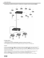
1
SIS
BEDIENUNGSANLEITUNG
OPERATING INSTRUCTIONS
Dolmetschersystem für Simultanübersetzungen
Simultaneous Interpretation System
Hinweis
Diese Bedienungsanleitung wendet sich an technisch qualifiziertes Personal, das speziell auf dem Gebiet der Elektrotechnik
ausgebildet ist. Die Kenntnis und das technisch einwandfreie Umsetzen der in dieser Bedienungsanleitung enthaltenen
Hinweise sind Voraussetzung für eine problemlose Installation und Inbetriebnahme sowie für die Sicherheit beim Betrieb der
beschriebenen Produkte.
In dieser Anleitung wird nicht jeder denkbare Fall der Installation, des Betriebs oder der Instandhaltung behandelt. Für weitere
Informationen steht Ihnen Ihr beyerdynamic-Händler oder beyerdynamic GmbH & Co. KG zur Verfügung.
beyerdynamic GmbH & Co. KG übernimmt keine Haftung für in dieser Dokumentation enthaltene Fehler sowie für beiläufige
oder Folgeschäden im Zusammenhang mit der Bereitstellung, Darstellung oder Verwendung dieser Dokumentation und der
darin beschriebenen Programme oder Produkte.
02
D
Inhalt
Inhaltsverzeichnis
1. Allgemeine Sicherheitshinweise Steuerzentrale und Dolmetscherpult SIS . . . . . . . . . . . . . . . . . . . . . . . . Seite
4
2. Aufstellung . . . . . . . . . . . . . . . . . . . . . . . . . . . . . . . . . . . . . . . . . . . . . . . . . . . . . . . . . . . . . . . . . . . . . . . . Seite
5
3. Das Dolmetschersystem SIS . . . . . . . . . . . . . . . . . . . . . . . . . . . . . . .
3.1
Allgemeine Informationen . . . . . . . . . . . . . . . . . . . . . . . . .
3.2
Das Dolmetscherpult SIS 1202 . . . . . . . . . . . . . . . . . . . . . . .
3.2.1 Anschlüsse, Bedien- und Kontrollelemente . . . . . . . . . . . .
3.2.2 Bedienung des Dolmetscherpultes . . . . . . . . . . . . . . . . . . .
Lautstärke, Klangregelung . . . . . . . . . . . . . . . . . . . . . . . . .
Einstellen der Zielsprache . . . . . . . . . . . . . . . . . . . . . . . . . .
Einstellen der Relaissprache . . . . . . . . . . . . . . . . . . . . . . . .
Hören der Originalsprache . . . . . . . . . . . . . . . . . . . . . . . . .
Hören der Relaissprache . . . . . . . . . . . . . . . . . . . . . . . . . . .
Einschalten des Mikrofons . . . . . . . . . . . . . . . . . . . . . . . . .
Mikrofon stummschalten . . . . . . . . . . . . . . . . . . . . . . . . . .
Mikrofon abschalten . . . . . . . . . . . . . . . . . . . . . . . . . . . . . .
Hilfe bei technischen Problemen . . . . . . . . . . . . . . . . . . . .
Gehörschutz . . . . . . . . . . . . . . . . . . . . . . . . . . . . . . . . . . . .
3.3
Die Steuerzentrale SIS 121/122/123 . . . . . . . . . . . . . . . . . . .
3.3.1 Anschlüsse, Bedien- und Kontrollelemente Steuerzentrale
.
.
.
.
.
.
.
.
.
.
.
.
.
.
.
.
.
.
.
.
.
.
.
.
.
.
.
.
.
.
.
.
.
.
.
.
.
.
.
.
.
.
.
.
.
.
.
.
.
.
.
.
.
.
.
.
.
.
.
.
.
.
.
.
.
.
.
.
.
.
.
.
.
.
.
.
.
.
.
.
.
.
.
.
.
.
.
.
.
.
.
.
.
.
.
.
.
.
.
.
.
.
.
.
.
.
.
.
.
.
.
.
.
.
.
.
.
.
.
.
.
.
.
.
.
.
.
.
.
.
.
.
.
.
.
.
.
.
.
.
.
.
.
.
.
.
.
.
.
.
.
.
.
.
.
.
.
.
.
.
.
.
.
.
.
.
.
.
.
.
.
.
.
.
.
.
.
.
.
.
.
.
.
.
.
.
.
.
.
.
.
.
.
.
.
.
.
.
.
.
.
.
.
.
.
.
.
.
.
.
.
.
.
.
.
.
.
.
.
.
.
.
.
.
.
.
.
.
.
.
.
.
.
.
.
.
.
.
.
.
.
.
.
.
.
.
.
.
.
.
.
.
.
.
.
.
.
.
.
.
.
.
.
.
.
.
.
.
.
.
.
.
.
.
.
.
.
.
.
.
.
.
.
.
.
.
.
.
.
.
.
.
.
.
.
.
.
.
.
.
.
.
.
.
.
.
.
.
.
.
.
.
.
.
.
.
.
.
.
.
.
.
.
.
.
.
.
.
.
.
.
.
.
.
.
.
.
.
.
.
.
.
.
.
.
.
.
.
.
.
.
.
.
.
.
.
.
.
.
.
.
.
.
.
.
.
.
.
.
.
.
.
.
.
.......
.......
.......
.......
.......
.......
.......
.......
.......
.......
.......
.......
.......
.......
.......
.......
.......
Seite
Seite
Seite
Seite
Seite
Seite
Seite
Seite
Seite
Seite
Seite
Seite
Seite
Seite
Seite
Seite
Seite
6
6
6
6
9
9
9
9
10
10
10
10
11
11
11
12
12
4. Aufbau des Systems und Inbetriebnahme. . . . . . . . . . . . . . . . . . . . . . . . . . . . . . . . . . . . . . . . . . . . . . . . .
Steuerzentrale vorbereiten . . . . . . . . . . . . . . . . . . . . . . . . . . . . . . . . . . . . . . . . . . . . . . . . . . . . . .
Dolmetscherpult vorbereiten . . . . . . . . . . . . . . . . . . . . . . . . . . . . . . . . . . . . . . . . . . . . . . . . . . . .
System in Betrieb nehmen . . . . . . . . . . . . . . . . . . . . . . . . . . . . . . . . . . . . . . . . . . . . . . . . . . . . . .
Anwendung SIS Dolmetschersystem, drahtloses digitales Konferenzsystem MCW-D und
drahtloses Translation-Tourguide-System TTS 300 . . . . . . . . . . . . . . . . . . . . . . . . . . . . . . . . . . . .
Anwendung SIS Dolmetschersystem und drahtloses digitales Konferenzsystem MCW-D . . . . . .
Seite
Seite
Seite
Seite
14
14
14
14
Seite
Seite
16
18
5. Konfiguration . . . . . . . . . . . . . . . . . . . . . . . . . . . . . . . . . . . . . . . . . . . . . . . . . . . . . . . . . . . . . . . . . . . . . . Seite
19
6. Zubehör . . . . . . . . . . . . . . . . . . . . . . . . . . . . . . . . . . . . . . . . . . . . . . . . . . . . . . . . . . . . . . . . . . . . . . . . . . . Seite
22
7. Technische Daten. . . . . . . . . . . . . . . . . . . . . . . . . . . . . . . . . . . . . . . . . . . . . . . . . . . . . . . . . . . . . . . . . . . . Seite
23
Anhang - Funktionsbeschreibung EarPatron-Technologie . . . . . . . . . . . . . . . . . . . . . . . . . . . . . . . . . . . . . . . Seite
26
Konformitätserklärung . . . . . . . . . . . . . . . . . . . . . . . . . . . . . . . . . . . . . . . . . . . . . . . . . . . . . . . . . . . . . . . . . . Seite
58
D
03
Sicherheitshinweise
1.
•
•
•
•
•
•
•
•
•
•
•
•
•
•
•
•
•
•
•
•
•
•
•
•
•
•
•
Allgemeine Sicherheitshinweise Steuerzentrale und Dolmetscherpult SIS
LESEN Sie die Bedienungsanleitung.
BEWAHREN Sie diese Bedienungsanleitung auf.
BEFOLGEN Sie die aufgeführten Bedienungs- und Sicherheitshinweise.
Das Gerät muss so aufgestellt werden, dass die Steckverbindung leicht zugänglich ist.
Das Gerät muss an eine Netz-Steckdose mit Schutzkontakt angeschlossen werden.
Setzen Sie das Gerät niemals Regen oder hoher Feuchtigkeit aus. Installieren Sie es daher nicht in unmittelbarer Nähe von
Swimming Pools, Duschanlagen, feuchten Kellerräumen oder sonstigen Bereichen mit außergewöhnlich hoher
Luftfeuchtigkeit.
Stellen Sie niemals mit Flüssigkeiten gefüllte Gegenstände (z.B. Vasen oder Trinkgläser) auf das Gerät. Denn Flüssigkeiten in
den Geräten können einen Kurzschluss verursachen.
Reinigen Sie das Gerät nur mit einem leicht feuchten oder trockenem Tuch. Verwenden Sie niemals Lösungsmittel, da diese
die Oberfläche beschädigen.
Installieren und betreiben Sie das Gerät auch niemals in unmittelbarer Nähe von Heizkörpern, Beleuchtungsanlagen oder
anderen wärmeerzeugenden Geräten.
Verlegen Sie alle Kabel stets so, dass sie nicht durch scharfe Gegenstände geknickt oder gar durchgetrennt werden können.
Verlegen Sie alle Anschlusskabel so, dass niemand darüber stolpern und sich verletzen kann.
Schalten Sie bei allen Arbeiten an den Ein- und Ausgängen die Stromzufuhr aus.
Überprüfen Sie, ob die Anschlusswerte mit der vorhandenen Netzstromversorgung übereinstimmen. Bei Anschluss des
Systems an die falsche Stromversorgung können ernsthafte Schäden entstehen. Eine falsche Netzspannung kann das Gerät
beschädigen oder einen elektrischen Schlag verursachen.
Dieses Gerät benötigt eine ausreichende Ventilation. Decken Sie die Lüftungsöffnungen nicht ab. Wenn die Eigenwärme
nicht abgeführt wird, kann das Gerät beschädigt oder brennbare Materialien in unmittelbarer Nähe können entzündet werden. Achten Sie daher darauf, dass die Luft durch die Lüftungsöffnungen frei zirkulieren kann und halten Sie brennbare
Materialien fern.
Stellen Sie niemals offene Brandquellen (z.B. Kerzen) auf das Gerät.
Wenn Sie defektes oder ungeeignetes Zubehör anschließen, kann das Gerät beschädigt werden. Verwenden Sie daher nur
die von beyerdynamic lieferbaren oder empfohlenen Anschlusskabel. Verwenden Sie selbstkonfektionierte Kabel, erlischt Ihr
Garantieanspruch.
Wenn Sie das Gerät an einen anderen Ort transportieren, achten Sie darauf, dass es ausreichend gesichert ist und niemand
durch ein eventuelles Herunterfallen oder Stoßen am Gerät verletzt werden kann.
Nehmen Sie das Gerät bei einem Gewitter oder wenn Sie es längere Zeit nicht benutzen vom Netz.
Wenn durch das Gerät eine Sicherung defekt oder ein Kurzschluss verursacht wurde, nehmen Sie es vom Netz und lassen Sie
es überprüfen und reparieren.
Öffnen Sie nicht eigenmächtig das Gerät. Sie könnten einen elektrischen Schlag erleiden. Überlassen Sie alle Servicearbeiten
nur autorisiertem Fachpersonal.
Fassen Sie das Netzkabel nicht mit nassen Händen an und an den Kontaktstiften sollte sich kein Wasser oder Staub befinden.
In beiden Fällen könnten Sie einen elektrischen Schlag erleiden.
Das Netzkabel muss fest angeschlossen sein. Ist es lose, besteht Brandgefahr.
Ziehen Sie das Netzkabel immer am Stecker vom Netz und/oder vom Gerät - niemals am Kabel. Das Kabel könnte beschädigt
werden und einen elektrischen Schlag oder Brand verursachen.
Wenn das Netzkabel angeschlossen ist, bringen Sie das Gerät nicht mit anderen metallischen Gegenständen in Berührung.
Berühren Sie den Kontaktstifte des Steckers nicht, nachdem Sie das Gerät vom Netz getrennt haben, Sie könnten einen elektrischen Schlag erleiden.
Stecken Sie weder Drähte noch andere Gegenstände in die Lüftungs- und andere Öffnungen. Sie könnten das Gerät beschädigen und/oder sich verletzen.
Setzen Sie das Gerät nicht ein, wenn der Netzstecker beschädigt ist.
Sicherheitsinfos für Kopfhörer / Headsets
• Wenn Sie den Kopfhörer / Headset anschließen, achten Sie darauf, dass die Lautstärke (Volume) auf Minimum gedreht ist.
Regeln Sie die Lautstärke erst nach Aufsetzen des Hörers. Stellen Sie die Lautstärke nicht zu hoch ein. Sie können Ihr Gehör
dauerhaft schädigen.
• Bei kabelgebundenen Kopfhörern / Headsets sollten Sie heftige Bewegungen vermeiden, bei denen der Hörer vom Kopf fallen kann. Sie könnten sich ernsthaft verletzen, insbesondere, wenn Sie Piercings, Ohrringe, Brille usw. tragen. Das Kabel
könnte sich um den Hals wickeln und zur Strangulation führen.
04
D
Hinweise zur Aufstellung
2.
Aufstellung
Das Dolmetschersystem SIS ist zur Aufstellung auf einen Tisch vorgesehen. Bei der Aufstellung müssen Sie die
Sicherheitsinformationen in Kapitel 1 beachten.
Insbesondere und darüber hinaus
•
•
•
•
•
•
darf die Umgebungstemperatur am Aufstellungsort 40°C nicht überschreiten.
darf der Aufstellungsort keiner übermäßigen Staub- und Feuchtigkeitsentwicklung ausgesetzt sein.
sollte das Gerät keiner direkten Sonneneinstrahlung ausgesetzt sein.
müssen die Anschlüsse vor direktem Zugriff während des Betriebes geschützt sein.
müssen die Zuleitungen gegebenenfalls durch extern anzubringende Vorrichtungen zugentlastet werden.
muss der Aufstellungsort vor Vibrationen geschützt sein.
D
05
Dolmetscherpult SIS 1202
3.
Das Dolmetschersystem SIS
3.1 Allgemeine Informationen
Das Dolmetschersystem SIS besteht aus der Steuerzentrale SIS 121/122/123, dem Dolmetscherpult SIS 1202 und der HörsprechKombination DT 394.SIS.
Das Dolmetscherpult SIS 1202 dient dem Dolmetscher in der Kabine zur Wahl der Kanäle, in die er spricht und welche er hören
möchte. Er trägt die Hörsprech-Kombination DT 394.SIS oder arbeitet mit einem Tischmikrofon und einem Kopfhörer. Das
Dolmetscherpult ist über ein spezielles Kabelsystem an die Steuerzentrale angeschlossen. Die Steuerzentrale verwaltet die Einund Ausgangskanäle des Dolmetschersystems. Eingespeist wird der Originalton aus dem Saal, einem Filmvorführgerät oder
anderen Quellen. Als Ausgangssignale stehen die einzelnen Dolmetscherkanäle zur Verfügung, die dann an angeschlossene
Kopfhörer oder an ein Konferenzsystem weitergegeben werden.
3.2 Das Dolmetscherpult SIS 1202
Das Bedienfeld von SIS 1202 ist als Doppelpult für zwei Dolmetscher ausgelegt. Damit diese eine Rede mithören und simultan
dolmetschen können, werden an das Pult Mikrofon und Kopfhörer oder eine Hörsprech-Kombination (Headset) angeschlossen.
Die einzelnen Bedienelemente sind so angeordnet, dass der Dolmetscher sie intuitiv bedienen kann. Das Dolmetscherpult wird
an die Steuerzentrale angeschlossen. Standardmäßig können bis zu 4 Dolmetscherpulte im Einkabelprinzip an eine
Steuerzentrale angeschlossen werden. Optional kann die Steuerzentrale mit zwei weiteren Einschüben à 4 Anschlüssen für weitere Fremdsprachen bestückt werden, so dass insgesamt 12 Dolmetscherpulte im Einkabelprinzip angeschlossen werden können.
3.2.1 Anschlüsse, Bedien- und Kontrollelemente
Oberseite
6
6
6
6
6
6
6
6
6
6
2
2
15
5
5
10
10
8
9
7
7
7
7
7
7
7
7
12
7
9
4
13
12
1
EarPatron
11
11
3
14
D
13
1
EarPatron
06
8
7
14
Dolmetscherpult SIS 1202
1
Talk = Sprechtaste
LED grün = Mikrofon ein
LED rot = Kanal wird bereits besprochen
LED aus = Mikrofon aus
2
On Air
LED leuchtet, wenn das Mikrofon eingeschaltet ist
3
Mute = Räuspertaste zum Stummschalten des Mikrofons (bei Bedarf gedrückt halten; nicht drehen)
4
Off-Taste
zum Ausschalten des Mikrofons
5
Language Select-Taste gedrückt halten
und eine der oberen „Relay“-Tasten 6 gleichzeitig drücken = Einstellen der Relaissprache, die gehört werden kann
(jeweilige LED der vorgewählten Sprache leuchtet grün).
5
Language Select-Taste gedrückt halten
und eine der unteren „Mic Out“-Tasten 7 gleichzeitig drücken = Einstellen der Sprache, in die übersetzt wird
(jeweilige LED der vorgewählten Sprache leuchtet grün)
6
obere Relay-Taste = Wählen der Relaissprache, die gehört werden soll (jeweilige LED leuchtet grün).
7
untere Mic Out-Taste = Wählen der Sprache, in die übersetzt wird (jeweilige LED leuchtet grün).
8
Original-Taste
Taste drücken, wenn die Originalsprache gehört werden soll -> LED leuchtet grün
9
Relay-Taste
Taste drücken, wenn die ausgewählte Relaissprache
6
gehört werden soll -> LED leuchtet grün
10
Service-Taste
bei technischen Problemen drücken:
LED rot = Ruf zum Techniker
LED grün = Techniker hat Ruf empfangen und bestätigt
11
Volume = Lautstärkeregler für Kopfhörer
12
Bass = Tiefenregler für Kopfhörer
13
Treble = Höhenregler für Kopfhörer
14
Gehörschutzfunktion. Funktion kann mit Kugelschreiber ein-/ausgeschaltet werden.
„Active“-LED leuchtet grün -> Funktion aktiviert
„Active“-LED leuchtet rot -> eingestellte Lautstärke ist zu hoch
ACHTUNG:
Wird der Gehörschutz ausgeschaltet, wenn die „Active“-LED rot leuchtet, kann es zu großen
Lautstärkesprüngen kommen, die im schlimmsten Fall zu Gehörschäden führen können.
15
Display-Anzeige
1. Zeile = Anzeige Relaissprache/n
Großbuchstaben = Kanal belegt; Sprache wird gerade gesprochen
Kleinbuchstaben = Kanal frei; Sprache wird nicht gesprochen
2. Zeile = Infozeile frei programmierbar über Steuerzentrale (Anzeige wer gerade spricht oder Nachricht usw.)
3. Zeile = Anzeige Uhrzeit und „EarPatron“ Dosis
4. Zeile = Sprache/n, in die übersetzt wird
D
07
Dolmetscherpult SIS 1202
Rechte Sprechstellenseite
18
17
DAN
20
21
19
22
16
16
17
18
19
20
21
22
Kartenleser
Netzwerkausgang (Anschluss zum nächsten Dolmetscherpult)
Netzwerkeingang (Anschluss von der Steuerzentrale oder des vorhergehenden Dolmetscherpultes)
Remote-Buchse für Fernbedienung des Mute-Tasters
Mikrofoneingang mit 12 V Phantomspeisung zum Anschluss eines Mikrofons
Kopfhöreranschluss 6,35 mm Klinke
Kopfhöreranschluss 3,5 mm Klinke, kann auch zum Anschluss eines Kassettenrekorders o.ä. dienen
Linke Sprechstellenseite
20
19
21
22
23
16
16 , 19
23
08
bis 22 dito
Anschluss für Netzspeiseteil
D
Dolmetscherpult SIS 1202
3.2.2 Bedienung des Dolmetscherpultes
Lautstärke, Klangregelung
Die Lautstärke, Höhen und Tiefen des an das Dolmetscherpult angeschlossenen Kopfhörers
/ Headsets können wie folgt eingestellt werden:
• Mit dem Lautstärkeregler 11 können Sie die Lautstärke des angeschlossenen Kopfhörers /
Headsets verändern.
• Mit dem Tiefenregler 12 können Sie die Bässe / Tiefen des angeschlossenen Kopfhörers /
Headsets verändern.
• Mit dem Höhenregler 13 können Sie die Höhen des angeschlossenen Kopfhörers /
Headsets verändern.
12
13
EarPatron
11
Einstellen der Zielsprache
Zum Dolmetschen in die Zielsprache muss diese am
Dolmetscherpult eingestellt werden. Zuvor müssen
alle Sprachen, die in der Konferenz gesprochen werden, an der Steuerzentrale eingestellt werden. Siehe
hierzu auch Kapitel 5. Konfiguration - Eingabe der
5
Sprachen.
• Halten Sie die Taste „Language Select“ 5
gedrückt und stellen Sie durch mehrmaliges
Drücken der Taste „Mic Out“ 7 die gewünschte
Zielsprache ein.
• Sollen weitere Zielsprachen eingestellt werden,
7
7
halten Sie wieder die Taste „Language Select“ 5
gedrückt und stellen mit der nächsten Taste „Mic
Out“ 7 in der Reihe die gewünschte Zielsprache ein.
• Wiederholen Sie diese Schritte so oft, bis alle Zielsprachen eingestellt sind.
• Die LED der „Mic Out“ Taste für die ausgewählte Zielsprache leuchtet grün.
Einstellen der Relaissprache
Wird nicht aus der Originalsprache, sondern einer
Zwischenübersetzung (= Relaissprache) eines anderen
Dolmetschers gedolmetscht, muss diese Relaissprache
eingestellt werden. Zuvor müssen alle Sprachen, die
in der Konferenz gesprochen werden, an der
Steuerzentrale eingestellt werden. Siehe hierzu auch
Kapitel 5. Konfiguration - Eingabe der Sprachen.
6
6
5
7
7
7
7
7
7
7
7
6
6
6
6
6
6
6
6
5
• Halten Sie die Taste „Language Select“ 5
gedrückt und und stellen Sie durch mehrmaliges
Drücken der Taste „Relay“ 6 die gewünschte
Relaissprache ein.
• Sollen weitere Relaissprachen eingestellt werden,
halten Sie wieder die Taste „Language Select“ 5 gedrückt und stellen mit der nächsten Taste „Relay“
gewünschte Relaissprache ein.
• Wiederholen Sie diese Schritte so oft, bis alle gewünschten Relaissprachen eingestellt sind.
• Die LED der „Relay“ Taste für die ausgewählte Relaissprache leuchtet grün.
5
6
in der Reihe die
WICHTIG:
• Ein belegter Kanal wird im Display mit Großbuchstaben dargestellt; d.h. die jeweilige Sprache wird gerade gesprochen.
• Ein freier Kanal wird im Display mit Kleinbuchstaben dargestellt; d.h. die jeweilige Sprache wird im Moment nicht gesprochen.
• Nicht besprochene Kanäle werden von der SIS Steuerzentrale automatisch mit dem Signal der Originalsprache (Floor) belegt.
D
09
Dolmetscherpult SIS 1202
Hören der Originalsprache
• Wenn der Dolmetscher aus der Originalsprache dolmetscht, muss die Taste „Original“
werden, damit er die Originalsprache über Kopfhörer hört.
• Die grüne LED der Taste „Original“ leuchtet.
8
gedrückt
8
Hören der Relaissprache
6
6
6
6
6
6
6
6
6
6
Wenn der Dolmetscher aus einer Relaissprache dolmetscht, muss diese zuvor wie unter „Einstellen der
Relaissprache“ beschrieben, eingestellt werden.
• Damit der Dolmetscher die Relaissprache über
Kopfhörer hört, muss die entsprechende
Relaissprache mit „Relay“ 6 ausgewählt sein,
sowie die Taste „Relay“ 9 gedrückt sein.
• Die grüne LED der Taste „Relay“ 9 leuchtet.
WICHTIG:
• Wird die ausgewählte Relaissprache nicht gesprochen, wird automatisch das Signal der
Originalsprache durchgeschaltet.
9
9
Einschalten des Mikrofons
Damit die Teilnehmer der Konferenz die Übersetzung
des Dolmetschers hören können, muss das Mikrofon
eingeschaltet werden.
• Drücken Sie am Dolmetscherpult die Taste „Talk“ 1 ,
die zugehörige LED muss grün leuchten.
• Gleichzeitig leuchtet die rote „On Air“-LED 2 .
• Die „Talk“-Taste 1 besitzt eine Toggle-Funktion,
d.h. wird z.B. die „Talk“-Taste 1 auf der linken
Seite des Pultes gedrückt, wenn das Mikrofon der
rechten Seite eingeschaltet ist, wird dieses ausgeschaltet und umgekehrt.
2
2
1
1
WICHTIG:
• Es ist nicht möglich, dass zwei Dolmetscher gleichzeitig dieselbe Sprache sprechen können. In diesem Fall kann das Mikrofon
nicht eingeschaltet werden, die LED der „Talk“-Taste 1 leuchtet rot und geht dann aus.
Mikrofon stummschalten
• Zum Stummschalten des Mikrofons drücken Sie die „Mute“-Taste 3 und halten Sie sie
gedrückt. Die „On Air“-LED 2 geht aus.
• Zum Wiedereinschalten des Mikrofons lassen Sie die Mute-Taste 3
los. Die „On Air“-LED 2 geht wieder an.
1
1
3
10
D
Dolmetscherpult SIS 1202
Mikrofon abschalten
• Zum Abschalten des Mikrofons drücken Sie die Off-Taste
LED der „Talk“-Taste 1 gehen aus.
4
. Die „On Air“-LED
2
und die
4
Hilfe bei technischen Problemen
Treten technische Probleme auf, kann der
Dolmetscher dem Techniker an der SIS Steuerzentrale
ein Signal übermitteln.
• Drückt der Dolmetscher auf die Taste „Service“ 10 ,
erhält der Techniker an der SIS Steuerzentrale eine
Meldung.
• Die zugehörige LED der Taste „Service“ 10 leuchtet
rot.
• Durch nochmaliges Drücken der Taste „Service“ 10
wird der Ruf gelöscht, die LED der Taste „Service“
erlischt und die Meldung an der SIS Steuerzentrale
verschwindet.
• Wenn der Techniker den Ruf über die SIS
Steuerzentrale empfangen und bestätigt hat,
leuchtet die LED der Taste „Service“ grün und geht
nach ca. 10 Sekunden aus.
10
10
EarPatron
EarPatron
Gehörschutz
EarPatron
EarPatron
14
14
Das Dolmetscherpult ist mit einer Gehörschutzfunktion ausgestattet.
• Standardmäßig ist der Gehörschutz 14 nach dem
Einschalten der SIS-Anlage aktiv.
• Die „Active“-LED leuchtet grün.
• Leuchtet die „Active“-LED rot, heißt das, die eingestellte Lautstärke ist zu hoch und der Gehörschutz
begrenzt die Lautstärke momentan.
• Zum Aus- und Einschalten des Gehörschutzes 14 drücken Sie z.B. mit einem Kugelschreiber in die Vertiefung neben der
„Active“-LED.
• Im Display des Dolmetscherpultes wird angezeigt, wieviel Prozent des Grenzwertes der Lautstärke bereits erreicht wurden.
ACHTUNG:
Wird der Gehörschutz ausgeschaltet, wenn die „Active“-LED rot leuchtet, kann es zu großen Lautstärkesprüngen
kommen, die im schlimmsten Fall zu Gehörschäden führen können.
Siehe auch Funktionsbeschreibung der Gehörschutz-Technologie im Anhang.
D
11
Steuerzentrale SIS 121/122/123
3.3
Die Steuerzentrale SIS 121/122/123
Die modular erweiterbare Steuerzentrale verwaltet bis zu 12 Dolmetscherpulte gleichzeitig. Dadurch wird das Übersetzen einer
Rede in maximal 12 Sprachen ermöglicht. Die Basis-Version der Steuerzentrale ist mit einem Originalkanal und 4 Fremdkanälen
ausgestattet. Durch bis zu zwei zusätzliche Einschubmodule mit jeweils 4 weiteren Ausgangskanälen ist eine Erweiterung auf 8
oder 12 Fremdkanäle möglich. Angeschlossen werden die Dolmetscherpulte mit handelsüblichen Standard-Netzwerkkabeln
(CAT.5) oder speziellen trittfesten Kabeln von beyerdynamic. Die Konfiguration des SIS Systems erfolgt über ein integriertes
5,5" Touch-Panel.
3.3.1 Anschlüsse, Bedien- und Kontrollelemente Steuerzentrale
Vorderseite
4
3
1
2
1
Lautstärkeregler für Kopfhöreranschluss
2
Kopfhöreranschluss, 6,3 mm Klinke
3
5,5" Touch-Panel
44
Power LED
12
D
2
Steuerzentrale SIS 121/122/123
Rückseite
18
22
19
21
20
8
6
10
6
7
6
7
6
7
7
9
17
16
15 14
12
11
13
5
5
Ausgang, sym. 15-pol. Sub-D, mit schaltbarer O-Tonunterdrückung (Ausgangskabel CA 3201 wird benötigt)
6
Ausgang, sym. 3-pol. XLR, z.B. zum Anschluss von stationären Sendern wie CT 316; untere Reihe „A“, mittlere Reihe „B“,
obere Reihe „C“
7
Ausgang, unsym. Cinch zum Anschluss von Kassettenrekorder o.ä. Geräten
8
„Digital Audio Network“ - DAN-Anschluss für Dolmetscherpulte (Einkabelprinzip)
9
10
Eingang (from MCW-D) /
Ausgang (to MCW-D - Kabel CA 3125 verwenden) 25-pol. Sub-D z.B. zum Anschluss eines Konferenzsystems wie MCW-D von
beyerdynamic
11
Eingang, sym. 3-pol. XLR, für Original-Signal (wenn kein Konferenzsystem am Eingang
12
Ausgang zum Durchschleifen des Original-Signals, wenn z.B. mehrere SIS-Steuerzentralen miteinander verbunden werden.
13
Umschalter dient zum Umschalten zwischen Eingang
14
Pegelschalter zum Umschalten der Empfindlichkeit zwischen +6 dB und -10 dB
15
Ground-Lift-Schalter
16
Eingang für externe Relais-Sprache
17
Ausgang zum Durchschleifen der Relais-Sprache, wenn z.B. mehrere SIS-Steuerzentralen miteinander verbunden sind.
18
Netzanschluss
19
Ein-/Ausschalter
20
RS 232-Anschluss für PC
21
LAN-Anschluss für PC (Netzwerk)
22
Netzsicherung
9
und
9
angeschlossen ist)
11
ACHTUNG
• Im Innern der Steuerzentrale befindet sich eine Lithium-Batterie (CR2032). Ersetzen Sie diese bei Bedarf nur
durch denselben oder einen gleichwertigen Typ. Bei unsachgemäßem Auswechseln der Batterie besteht
Explosionsgefahr.
D
13
Inbetriebnahme
4.
Aufbau des Systems und Inbetriebnahme
In diesem Kapitel lesen Sie, wie Sie das Dolmetschersystem SIS aufbauen und in Betrieb nehmen.
Steuerzentrale vorbereiten
• Schließen Sie das Netzkabel an der Anschlussbuchse
Stromnetz (100 - 240 V, 50 - 60 Hz) an.
18
18
19
und am
4
• Schalten Sie die Steuerzentrale mit dem Ein-/Ausschalter 19 ein.
Die grüne Power-LED 4 leuchtet. Nach ca. 30 Sekunden erscheint
der Hauptbildschirm auf dem Touch-Panel.
Dolmetscherpult anschließen
• Schließen Sie das mitgelieferte Netzteil an das Dolmetscherpult
und ans Netz an.
23
• Schließen Sie den Eingang (DAN In) 18 des ersten
Dolmetscherpultes an die DAN-Buchse 8 der Steuerzentrale an.
Verwenden Sie hierfür ein CAT.5 Kabel mit RJ 45 Stecker.
8
• Verbinden Sie den Ausgang (DAN Out) 17 des ersten Pultes mit
dem Eingang (DAN In) 18 des zweiten Pultes usw. Maximal können in diesem Einkabelprinzip 12 Pulte an die DAN-Buchse 8
einer SIS Steuerzentrale angeschlossen werden.
18
17
DAN
System in Betrieb nehmen
• Stellen Sie den Lautstärkeregler 11 am
Dolmetscherpult auf Minimum und schließen Sie
ein Headset 21 und 20 oder 22 und 20 oder ein
Mikrofon 20 und einen Kopfhörer 21 oder 22 an.
12
13
20
EarPatron
11
14
D
22
21
Inbetriebnahme
• Schließen Sie das Audiosignal der Originalsprache
an die Steuerzentrale 11 an.
• Wenn ein Konferenzsystem von beyerdynamic verwendet wird, z.B. MCW-D, schließen Sie die
Steuerzentrale MCW-D mit den Kabeln CA 3125 (2
Stück) an den Ein- 9 und Ausgang 10 der
Steuerzentrale SIS an.
• Wählen Sie mit dem Umschalter 13 welcher
Eingang 9 oder 11 aktiviert werden soll.
11
• Drücken Sie auf die Taste „Original“ 8 und drehen Sie
den Lautstärkeregler 11 am Dolmetscherpult langsam auf.
Sie sollten nun die Originalsprache über Kopfhörer hören,
sofern ein „Originalsignal“ anliegt.
13
9
10
8
8
EarPatron
EarPatron
11
11
• Wird eine externe Relaissprache verwendet, so
schließen Sie diese am Eingang 16 an. Bei
Verwendung einer internen Sprache als Relais
bleibt dieser Eingang frei.
16
• Stellen Sie die Relaissprache/n ein wie unter „Einstellen
der Relaissprache“ (Seite 9) beschrieben und drücken Sie
auf die Taste „Relay“ 9 . Sie sollten nun die Relaissprache
über Kopfhörer hören, sofern der Relaiskanal besprochen
wird. Wird die Relaissprache nicht gesprochen, ist hier
automatisch das Originalsignal zu hören.
• Wird die Dolmetscheranlage zusammen mit einem
Konferenzsystem wie z.B. MCW-D 200 von beyerdynamic eingesetzt, schließen Sie die Steuerzentrale des Konferenzsystems an den Ein- 9 und
Ausgang 10 der SIS Steuerzentrale an.
• Wird die Dolmetscheranlage zusammen mit einer
Führungsanlage wie z.B. TTS 300 von beyerdynamic
betrieben, schließen Sie den Stationären Sender
CT 316 an die Ausgänge 6 der SIS Steuerzentrale
an.
9
9
EarPatron
EarPatron
19
10
9
6
6
D
15
Inbetriebnahme
Anwendung SIS Dolmetschersystem, drahtloses, digitales Konferenzsystem MCW-D und
drahtloses Translation-Tourguide-System TTS 300
AD 707 NHF Set
Benötigtes Zubehör:
1 x MCW-D 200 Steuerzentrale
1 x CA 3125 Kabel zum Anschluss der MCW-D 200 Steuerzentrale an die SIS 121 Steuerzentrale
1 x Mikrofonkabel
1 x MCW-D 2073 Präsidentensprechstelle mit Display und Kopfhörer zum Abhören der Fremdsprachen
mehrere MCW-D 2071 Delegiertensprechstellen mit Display und Kopfhörer zum Abhören der Fremdsprachen
1 x CT 316 stationärer Sender für Originalsprache
3 x CT 316 stationärer Sender für 3 Fremdsprachen
1 x ZAC 41 Combiner 4 auf 1 für Sendepegel
1 x CA 2431 Kabel, dämpfungsarm mit CA 2447 Antennenkabeladapter
1 x AD 707 NHF Set Groundplaneantenne
mehrere FE 316 Taschenempfänger und Kopfhörer zum Abhören der Fremdsprachen
16
D
Inbetriebnahme
Anschluss
Verbinden Sie den Eingang (DAN In) 18 des ersten Dolmetscherpultes mit der DAN-Buchse 8 der SIS Steuerzentrale. Verbinden
Sie den Ausgang (DAN Out) 17 des ersten Dolmetscherpultes mit dem Eingang (DAN In) 18 des zweiten Pultes usw. Zum
Anschluss des ersten Pultes an die SIS Steuerzentrale verwenden Sie z.B. das Kabel CA 3110 (10 Meter lang). Für die Verbindung
der Pulte untereinander verwenden Sie z.B. das Kabel CA 3105 (5 Meter lang). An die Dolmetscherpulte können Sie z.B. das
Headset DT 394.SIS anschließen.
Verbinden Sie den Eingang (In) der Erweiterungsplatine CA 2451 (25-pol. Sub-D) der MCW-D 200 Steuerzentrale mit dem
Ausgang (to MCW-D) 10 der SIS Steuerzentrale sowie den Ausgang (Out) der MCW-D 200 Steuerzentrale mit dem Eingang
(from MCW-D) 9 der SIS Steuerzentrale. Verwenden Sie hierfür jeweils das Kabel CA 3125.
Für den Anschluss an die MCW-D Sprechstellen stehen verschiedene Hörer zur Verfügung, z.B. DT 1 S, DT 1 D und DT 2.
Sollen weitere Zuhörer die Konferenz mitverfolgen ohne aktiv daran teilzunehmen (z.B. Presse), kann dies mit den
Führungsempfängern FE 316 mit Kopfhörer und den stationären Sendern CT 316 geschehen.
Verbinden Sie den Eingang (IN) eines stationären Senders CT 316 mit dem Ausgang 6 der SIS Steuerzentrale sowie für jede
Fremdsprache je einen stationären Sender CT 316 mit den entsprechenden Ausgängen 6 der SIS Steuerzentrale.
Standardmäßig können so eine Originalsprache und bis zu 4 Fremdsprachen angeschlossen werden. Ist die SIS Steuerzentrale
mit zwei weiteren Einschüben mit je 4 Anschlüssen bestückt, können maximal 1 Originalsprache und bis zu 12 Fremdsprachen
angeschlossen werden.
Verbinden Sie die Ausgänge der Sender CT 316 mit den Eingängen des Combiners ZAC 41/ZAC 81. Schließen Sie die Antenne
z.B. AD 707 NHF Set mit dem Kabel CA 2431 und dem Antennenkabeladapter CA 2447 an den Combiner an.
D
17
Inbetriebnahme
Anwendung SIS Dolmetschersystem und drahtloses, digitales Konferenzsystem MCW-D
Benötigtes Zubehör:
1 x MCW-D 200 Steuerzentrale
2 x CA 3125 Kabel zum Anschluss der MCW-D 200 Steuerzentrale an die SIS 121 Steuerzentrale
1 x MCW-D 2073 Präsidentensprechstelle mit Display und Kopfhörer zum Abhören der Fremdsprachen
mehrere MCW-D 2071 Delegiertensprechstellen mit Display und Kopfhörer zum Abhören der Fremdsprachen
Anschluss
Verbinden Sie den Eingang (DAN In) 18 des ersten Dolmetscherpultes mit der DAN-Buchse 8 der SIS Steuerzentrale. Verbinden
Sie den Ausgang (DAN Out) 17 des ersten Dolmetscherpultes mit dem Eingang (DAN In) 18 des zweiten Pultes usw. Zum
Anschluss des ersten Pultes an die SIS Steuerzentrale verwenden Sie z.B. das Kabel CA 3110 (10 Meter lang). Für die Verbindung
der Pulte untereinander verwenden Sie das z.B. Kabel CA 3105 (5 Meter lang). An die Dolmetscherpulte können Sie z.B. das
Headset DT 394.SIS anschließen.
Verbinden Sie den Eingang (In) der Erweiterungsplatine CA 2451 (25-pol. Sub-D) der MCW-D 200 Steuerzentrale mit dem
Ausgang (to MCW-D) 10 der SIS Steuerzentrale sowie den Ausgang (Out) der MCW-D 200 Steuerzentrale mit dem
Eingang (from MCW-D) 9 der SIS Steuerzentrale. Verwenden Sie hierfür jeweils das Kabel CA 3125.
Für den Anschluss an die MCW-D Sprechstellen stehen verschiedene Hörer zur Verfügung, z.B. DT 1 S, DT 1 D und DT 2.
18
D
Konfiguration SIS System
5.
Konfiguration SIS System
Das SIS System wird über ein integriertes Touch-Screen Display an der SIS Steuerzentrale konfiguriert. Alle Einstellungen, die Sie
hier vornehmen, werden auf die Dolmetscherpulte übertragen. Nach dem Einschalten der SIS Steuerzentrale leuchtet zuerst die
grüne Power-LED. Bis der Hauptbildschirm erscheint, dauert es ca. 30 Sekunden.
Hauptbildschirm
• Im Hauptbildschirm können Sie keine Einstellungen
vornehmen. Er dient zur Kontrolle der eingestellten
Sprachen und der Anzahl der angeschlossenen
Dolmetscherpulte.
• Über einen an der SIS Steuerzentrale angeschlossenen
Kopfhörer können Sie die Originalsprache (Floor)
sowie die einzelnen Fremdsprachen abhören. Die
jeweilige Sprache können Sie auswählen, indem Sie
auf die entsprechende Taste drücken.
• Die in der Reihe A, B und C eingestellten Sprachen
entsprechen den Ausgängen 6 bzw. 7 auf der
Rückseite der SIS Steuerzentrale.
• Ein roter Balken über dem jeweiligen Sprachkürzel
zeigt an, dass die Sprache von einem Dolmetscher
gesprochen wird.
• Unter „No. of Desks“ wird Ihnen die Anzahl der an der
SIS Steuerzentrale und am Strom angeschlossenen
Dolmetscherpulte angezeigt.
• Unter „about“ werden Infos zur Firmwareversion eingeblendet.
Eingabe der Sprachen
• Damit an den Dolmetscherpulten die Relais- und
Zielsprachen eingestellt werden können, müssen diese
Sprachen an der SIS Steuerzentrale eingestellt werden.
• Drücken Sie im Hauptbildschirm auf die Taste
„Language“.
• In diesem Sprachauswahlmenü können Sie alle
Sprachen auswählen, die in der Konferenz gesprochen
werden.
• Drücken Sie auf die jeweilige Taste z.B. A1.
• Eine Liste mit verschiedenen Sprachkürzeln wird geöffnet.
• Wählen Sie eine Sprache aus dieser Liste aus.
• Verfahren Sie mit den anderen Tasten genauso, bis alle
Sprachen, die auf der Konferenz gesprochen werden,
eingestellt sind.
• Zum Übertragen der eingestellten Sprachen auf die
Dolmetscherpulte drücken Sie die „OK“-Taste.
• Sollte für eine Sprache kein Sprachkürzel vorhanden
sein, können Sie dieses Kürzel über eine Tastatur eingeben. Drücken Sie hierfür die Taste „New“ und ein
Fenster mit einer Tastatur wird geöffnet.
• Geben Sie mit den entsprechenden Tasten den
Sprachkürzel ein. Beachten Sie, dass der Sprachkürzel
aus drei Buchstaben bestehen muss.
• Haben Sie sich vertippt, können Sie einzelne
Buchstaben mit der „Back“-Taste löschen.
• Drücken Sie die „OK“-Taste, damit der neue
Sprachkürzel in die oben genannte Liste aufgenommen wird.
• Im Menü „Language“ können Sie dann dieses
Sprachkürzel aus der Liste auswählen.
• Wollen Sie die Eingabe abbrechen, drücken Sie die
„Cancel“-Taste.
Tastatur zur Eingabe neuer Sprachkürzel
D
19
Konfiguration SIS System
Eingabe von Infozeilen
• Wollen Sie eine Nachricht oder Info an ein oder an alle
Dolmetscherpulte senden, drücken Sie im
Hauptbildschirm auf die Taste „Message“.
• Bereits vorhandene Nachrichten können Sie aus dem
Pull-Down-Menü auswählen, wenn Sie auf die
Pfeiltaste drücken und die entsprechende Nachricht
auswählen.
• Neue Nachrichten können Sie erstellen, wenn Sie auf
die Taste „Create New Message“ drücken. Ein Fenster
mit einer Tastatur wird geöffnet.
• Schreiben Sie mit der Tastatur die gewünschte
Nachricht und drücken Sie dann die „OK“-Taste. Sie
gelangen in das Menü „Message“ zurück und die neue
Nachricht erscheint im Pull-Down-Menü. Sie können
die Nachricht auswählen und versenden. Mit „Cancel“
können Sie die Eingabe abbrechen.
• Soll die Nachricht an alle Dolmetscherpulte gesendet
werden, drücken Sie auf die Taste „Display Message on
all desks“.
• Soll die Nachricht nur an ein Dolmetscherpult gesendet werden, stellen Sie das entsprechende Pult mit den
„+“ oder „-“ Tasten ein und drücken dann auf die
Taste „Display on desk no.“.
• Die Nachricht oder Info erscheint in der zweiten Zeile
im Display des Dolmetscherpultes.
• Wollen Sie die Nachricht bei allen Dolmetscherpulten
löschen, drücken Sie die Taste „Clear message on all
desks“.
• Wollen Sie die Nachricht nur an einem
Dolmetscherpult löschen, stellen Sie das entsprechende
Pult mit den „+“ oder „-“ Tasten ein und drücken
dann auf die Taste „Clear message on desk no.“
• Drücken Sie im Menü „Message“ auf die „OK“-Taste
wird der Hauptbildschirm wieder angezeigt.
Eingabe Zeit / Datum
• Zum Anzeigen von Uhrzeit und Datum im Display der
Dolmetscherpulte, drücken Sie im Hauptbildschirm auf
die Taste „Time/Date“.
• Sie können wählen, ob die Zeit im 24- oder 12Stundenmodus angezeigt werden soll.
• Unter „Time“ können Sie mit den jeweiligen
Pfeiltasten die aktuelle Uhrzeit einstellen.
h = Stunde, m = Minute, s = Sekunde.
• Unter „Date“ stellen Sie mit den jeweiligen Pfeiltasten
das aktuelle Datum ein.
Day = Tag, Month = Monat, Year = Jahr.
• Zum Speichern und Verlassen des Menüs drücken Sie
auf die Taste „OK“.
• Wollen Sie die Eingabe abbrechen, drücken Sie auf die
Taste „Cancel“.
20
D
Tastatur zur Eingabe neuer Nachrichten
Konfiguration SIS System
Eingabe Kenndaten Headset
• Zum Anpassen der Kopfhörerlautstärke in den
Dolmetscherpulten können Sie die Kenndaten des
Hörers wie Impedanz (Ohm) und Schalldruckpegel
(dB SPL) eingeben.
• Drücken Sie im Hauptbildschirm auf die Taste
„Headset“.
• Für verschiedene Headsets (DT 391, DT 394.SIS usw.)
sind alle Eingaben wie Impedanz (Ohm), Schalldruckpegel (dB SPL) und Mikrofon bereits vorgegeben.
EarPatron
Wählen Sie das am Dolmetscherpult angeschlossenene
Headset aus, indem Sie auf die entsprechende Taste
drücken, z.B. DT 391, DT 394.SIS.
• Falls ein anderes Headset verwendet wird, geben Sie
die entsprechende Impedanz (Ohm) und den
Schalldruckpegel (dB SPL) mit den „+“ und „-“ Tasten
ein. Impedanz und Schalldruckpegel finden Sie in den
Technischen Daten des jeweiligen Headsets.
• Stellen Sie ein, ob das verwendete Headset über ein Kondensator- oder dynamisches Mikrofon verfügt.
• Zum Übertragen der Daten an alle Dolmetscherpulte drücken Sie auf die Taste „Send to Desk“.
• Zum Verlassen des Menüs drücken Sie auf „Ok“.
• Soll die bereits erhaltene „Lärmdosis“, die ebenfalls im Display der Dolmetscherpulte angezeigt wird, auf „0“ gesetzt werden, drücken Sie die Taste „Reset EarPatron“.
Abrufen / Speichern von Presets
• Presets sind Voreinstellungen der SIS Steuerzentrale.
Insgesamt können 20 Presets abgerufen werden.
Beim Einschalten der SIS Steuerzentrale wird automatisch das Preset, das zuletzt aktiv war, geladen.
Laden
• Drücken Sie im Hauptbildschirm auf die Taste „Presets“,
wählen Sie ein Preset aus und drücken dann auf die
Taste „Load“.
• Die Meldung „Overwrite present values?“ erscheint.
Drücken Sie auf die Taste „Yes“. Das ausgewählte
Preset wird geöffnet und der Hauptbildschirm
erscheint.
• Sie können nun alle Einstellungen unter „Language“,
„Message“, „Time/Date“ und „Headset“ vornehmen.
Speichern
• Wollen Sie die Eingaben eines Presets überschreiben
und speichern, drücken Sie im Hauptbildschirm auf die
Taste „Presets“.
• Wählen Sie aus dem Pull-Down-Menü das Preset aus,
das Sie überschreiben und neu abspeichern wollen.
• Zum Speichern des Presets drücken Sie auf die Taste
„Preset“ und auf die Taste „Save“.
• Die Meldung „Overwrite Presetxx?“ erscheint.
• Wollen Sie alle Einstellungen als Preset speichern,
drücken Sie auf die Taste „Yes“.
• Wenn Sie auf die Taste „OK“ drücken, erscheint der
Hauptbildschirm.
D
21
Zubehör
Service-Ruf
• Drückt ein Dolmetscher am Dolmetscherpult die
„Service“-Taste, erscheint die Meldung „Service Call!
Please confirm“ sowie von welchem Dolmetscherpult
der Ruf abgesetzt wurde.
• Zum Bestätigen drücken Sie auf die rote Fläche in der
Spalte „left“ oder „right“, die für das jeweilige
Dolmetscherpult und die Seite (links bzw. rechts) angezeigt wird.
6.
Zubehör
Komponenten
SIS 1202
Dolmetscherpult für zwei Dolmetscher, inkl. Netzteil . . . . . . . . . . . . . . . . . . . . . . . . . . . Best.-Nr. 475.424
SIS 121
SIS 122
SIS 123
Zentrale mit einem Modul bestückt (= 4 Fremdkanäle) . . . . . . . . . . . . . . . . . . . . . . . . . . Best.-Nr. 458.783
Zentrale mit zwei Modulen bestückt (= 8 Fremdkanäle) . . . . . . . . . . . . . . . . . . . . . . . . . Best.-Nr. 458.767
Zentrale mit drei Modulen bestückt (= 12 Fremdkanäle) . . . . . . . . . . . . . . . . . . . . . . . . . Best.-Nr. 458.759
Systemkabel
CA 3101
CA 3105
CA 3110
CA 3125
CAT.5-Kabel mit trittfestem RJ-45 Metall-Stecker, 1 m . . . . . .
CAT.5-Kabel mit trittfestem RJ-45 Metall-Stecker, 5 m . . . . . .
CAT.5-Kabel mit trittfestem RJ-45 Metall-Stecker, 10 m . . . . .
Verbindungskabel SIS - MCW-D mit 25-pol. Sub-D-Anschluss.
.
.
.
.
.
.
.
.
.
.
.
.
.
.
.
.
.
.
.
.
.
.
.
.
.
.
.
.
.
.
.
.
.
.
.
.
.
.
.
.
.
.
.
.
.
.
.
.
.
.
.
.
.
.
.
.
.
.
.
.
.
.
.
.
.
.
.
.
.
.
.
.
.
.
.
.
.
.
.
.
.
.
.
.
Best.-Nr.
Best.-Nr.
Best.-Nr.
Best.-Nr.
475.440
475.319
475.327
476.579
Optionale Systemkomponenten
CA 3201
Adapter-Ausgangskabel, 15-pol. Sub-D, 4xXLR
(schaltbare O-Tonunterdrückung). . . . . . . . . . . . . . . . . . . . . . . . . . . . . . . . . . . . . . . . . . . Best.-Nr. 475.955
CA 3204
Vierkanal-Ausgangsmodul für SIS Dolmetscher-System . . . . . . . . . . . . . . . . . . . . . . . . . . Best.-Nr. 475.343
CA 3221
Dockingstation mit Lautsprecher und Schwanenhalsmikrofon . . . . . . . . . . . . . . . . . . . . Best.-Nr. 475.335
Optionale Kommunikationssysteme
CT 316
Stationärer UHF-Sender (863 - 865 MHz), 16-Kanal . . .
FE 316
Führungsempfänger (863 - 865 MHz), 16-Kanal . . . . . .
MCW-D 200
Steuerzentrale, 2,4 GHz, drahtloses Konferenzsystem .
MCW-D 2071 Delegiertensprechstelle mit Display . . . . . . . . . . . . . . .
MCW-D 2073 Präsidentensprechstelle mit Display . . . . . . . . . . . . . . .
CA 2431
Antennenkabel, dämpfungsarm, 10 Meter . . . . . . . . .
CA 2432
Antennenkabel, dämpfungsarm, 20 Meter . . . . . . . . .
CA 2447
Antennenkabeladapter N/HF(F)-N/HF(F) . . . . . . . . . . . .
ZAC 41
Combiner 4 auf 1 für Sendepegel (CT 316). . . . . . . . . .
ZAC 81
Combiner 8 auf 1 für Sendepegel (CT 316). . . . . . . . . .
Hörer
DT 394.SIS
DT
DT
DT
DT
DT
DT
1
1
1
1
2
2
22
S
S
D
D
D
.
.
.
.
.
.
.
.
.
.
.
.
.
.
.
.
.
.
.
.
.
.
.
.
.
.
.
.
.
.
.
.
.
.
.
.
.
.
.
.
.
.
.
.
.
.
.
.
.
.
. . . . . . . . . . . . . . . . . . . . . Best.-Nr. 472.832
. . . . . . . . . . . . . . . . . . . . . Best.-Nr. 472.840
. . . . . . . . . . . . . . . . . . . . . Best.-Nr. 472.522
. . . . . . . . . . . . . . . . . . . . . Best.-Nr. 472.751
. . . . . . . . . . . . . . . . . . . . . Best.-Nr. 472.778
. . . . . . . . . . . . . . . . . . . . . Best.-Nr. 464.309
. . . . . . . . . . . . . . . . . . . . . Best.-Nr. 464.325
. . . . . . . . . . . . . . . . . . . . . Best.-Nr. 476.587
. . . . . . . . . . . . . . . . . . . . . Best.-Nr. 476.552
. . . . . . . . . . . . . . . . . . . . . Best.-Nr. 476.560
Kopfhörerkombination für SIS Simultan-Dolmetscher-System, Hörer 40 Ω,
Kondensatormikrofon (Niere), Kabel mit 6,3 mm Stereo-Klinke und
3-pol. XLR-Stecker . . . . . . . . . . . . . . . . . . . . . . . . . . . . . . . . . . . . . . . . . . . . . . . . . . . . . . . Best.-Nr.
Einohrhörer, 32 Ω, Kabellänge 0,8 m, Mono-Klinke 3,5 mm . . . . . . . . . . . . . . . . . . . . . . Best.-Nr.
dito, jedoch Kabellänge 1,6 m . . . . . . . . . . . . . . . . . . . . . . . . . . . . . . . . . . . . . . . . . . . . . Best.-Nr.
Zweiohrhörer, 16 Ω, Kabellänge 0,8 m, Mono-Klinke 3,5 mm . . . . . . . . . . . . . . . . . . . . . Best.-Nr.
dito, jedoch Kabellänge 1,6 m . . . . . . . . . . . . . . . . . . . . . . . . . . . . . . . . . . . . . . . . . . . . . Best.-Nr.
Kopfhörer, 16 Ω, Kabellänge 0,8 m, Mono-Klinke 3,5 mm. . . . . . . . . . . . . . . . . . . . . . . . Best.-Nr.
dito, jedoch Kabellänge 1,6 m . . . . . . . . . . . . . . . . . . . . . . . . . . . . . . . . . . . . . . . . . . . . . Best.-Nr.
475.815
471.399
471.402
471.410
471.429
471.437
471.445
Technische Daten
7.
Technische Daten
Allgemein
Die Anlage entspricht den Normen:
IEC 60914 – Konferenzsysteme
DIN 56924 – Kabinen für Simultanübertragung
IEC 2603.2
CAT 5 Kabellänge (DAN) . . . . . . . . . . . . . . . . max. 70m zwischen 2 SIS Komponenten
Dolmetscherpult SIS 1202
Netzspannung externes Netzteil . . . . . . . . . . 110 – 240 VAC, 50/60 Hz
Belegung DC-Stecker, XRL 5-pol. . . . . . . . . . . 1 = +5 V
2 = +12 V
3 = Masse
4 = -12 V
5 = Masse
Abmessungen . . . . . . . . . . . . . . . . . . . . . . . . . Tiefe: 208 mm
Breite: 335 mm
Höhe vorne:17 mm
Höhe hinten: 98 mm
Betriebstemperaturbereich . . . . . . . . . . . . . . +5º bis +40ºC (bei < 90 % Luftfeuchtigkeit)
Lagertemperaturbereich . . . . . . . . . . . . . . . . -20º bis +80ºC (bei < 90 % Luftfeuchtigkeit)
Signalrauschabstand. . . . . . . . . . . . . . . . . . . . > 70 dB
Kanaltrennung . . . . . . . . . . . . . . . . . . . . . . . . > 70 dB bei Vollaussteuerung
Kopfhörerausgang 6,3 mm
Frequenzgang bez. auf 1 kHz
Klirrfaktor. . . . . . . . . . . . . . . .
max. Ausgangspegel . . . . . . .
........................
Fremdspannungsabstand
bez. auf Vollaussteuerung . . .
Anschlussnorm . . . . . . . . . . . .
.
.
.
.
.
.
.
.
.
.
.
.
.
.
.
.
.
.
.
.
.
.
.
.
.
.
.
.
.
.
.
.
.
.
.
.
.
.
.
.
. . 50 Hz – 20 kHz (-3dB)
. . < 1% bei Vollaussteuerung
. . an 20 Ω Last 2,2 Veff
. . an 300 Ω Last 6,3 Veff
. . . . . . . . . . . . 83 dB (Fremd) / 85 dB(A)
. . . . . . . . . . . . 3-pol Klinkenbuchse 6,3 mm, beide Kanäle belegt
Kopfhörerausgang 3,5 mm (Dokumentationsausgang)
Frequenzgang bez. auf 1 kHz . . . . . . . . . . . . 50 Hz – 20 kHz (-3dB)
Klirrfaktor. . . . . . . . . . . . . . . . . . . . . . . . . . . . < 1% bei Vollaussteuerung
max. Ausgangspegel . . . . . . . . . . . . . . . . . . . an 20 Ω Last 0,18 Veff
an 300 Ω Last 2,6 Veff
Fremdspannungsabstand
bez. auf Vollaussteuerung . . . . . . . . . . . . . . . 83 dB (Fremd) / 85 dB(A)
Anschlussnorm . . . . . . . . . . . . . . . . . . . . . . . . 3-pol Klinkenbuchse 3,5 mm, beide Kanäle belegt
Mikrofoneingang
Phantomspeisung . . . . . . . . . . . . . . . . . . . . . . +12 V
Belegung Mikrofonbuchse . . . . . . . . . . . . . . . 1 = Schirm
2 = NF+ / Phantomspeisung +12 V
3 = NF- / Phantomspeisung +12 V
Frequenzgang bez. auf 1 kHz . . . . . . . . . . . . 80 Hz – 20 kHz (-3dB)
Klirrfaktor. . . . . . . . . . . . . . . . . . . . . . . . . . . . < 1% bei Vollaussteuerung
Eingangsempfindlichkeit
bez. auf Vollaussteuerung . . . . . . . . . . . . . . . high: 11 mV (für dynamische Mikrofonkapseln)
low: 115 mV (für Elektretmikrofonkapseln)
Fremdspannungsabstand
bez. auf Vollaussteuerung . . . . . . . . . . . . . . . 85 dB (Fremd) / 87 dB(A)
Anschlussnorm . . . . . . . . . . . . . . . . . . . . . . . . 3-pol. XLR, female
D
23
Technische Daten
Hörsprech-Kombination DT 394.SIS
Mikrofon
Wandlerprinzip . . . . . . . . . . . . . . . . . . . . . . . Elektrekondensator
Speisung . . . . . . . . . . . . . . . . . . . . . . . . . . . . . über integrierten Impedanzwandler
Versorgungsbereich 11 – 52 V
Richtcharakteristik . . . . . . . . . . . . . . . . . . . . . Niere
Empfindlichkeit . . . . . . . . . . . . . . . . . . . . . . . 6 mV / PA
Ausgangsspannung beim Besprechen
aus 5 cm Abstand . . . . . . . . . . . . . . . . . . . . . . ca. 12 mV
Grenzschalldruck . . . . . . . . . . . . . . . . . . . . . . 122 dB SPL
Kopfhörersystem
Systemimpedanz. . . . . . . . . . . . . . . . . . . . . . . 40 Ω
Kennschalldruckpegel (1 mW bei 1 kHz) . . . . 94 dB SPL
Nennbelastbarkeit . . . . . . . . . . . . . . . . . . . . . 100 mW, entspricht 114 dB SPL
Gewicht ohne Kabel und Stecker. . . . . . . . . . 154 g
Gewicht mit Kabel und Stecker . . . . . . . . . . . 218 g
Steuerzentrale SIS 12x
Netzspannung . . . .
Netzsicherung. . . . .
Leistungsaufnahme
Anzeige . . . . . . . . .
Abmessungen . . . . .
.
.
.
.
.
.
.
.
.
.
.
.
.
.
.
.
.
.
.
.
.
.
.
.
.
.
.
.
.
.
.
.
.
.
.
.
.
.
.
.
.
.
.
.
.
.
.
.
.
.
.
.
.
.
.
.
.
.
.
.
.
.
.
.
.
.
.
.
.
.
.
.
.
.
.
.
.
.
.
.
.
.
.
.
.
.
.
.
.
.
.
.
.
.
.
.
.
.
.
.
110 – 240 VAC, 50/60 Hz
0,63 AT
18 W
5,5" Touchpanel, 256 Farbdisplay
Breite: 483 mm (19")
Tiefe: 310 mm
Höhe: 132 mm (3HE)
Betriebstemperaturbereich . . . . . . . . . . . . . . +5º bis +40ºC (bei < 90 % Luftfeuchtigkeit)
Lagertemperaturbereich . . . . . . . . . . . . . . . . -20º bis +80ºC (bei < 90 % Luftfeuchtigkeit)
Ausgänge
Original Through . . . . . . . . . . . . . . . . . . . . . . XLR male, 0 dB Verstärkung, Mindestimpedanz 300 Ω
Ext.Language Through . . . . . . . . . . . . . . . . . . XLR male, 0 dB Verstärkung, Mindestimpedanz 300 Ω
to MCW-D. . . . . . . . . . . . . . . . . . . . . . . . . . . . 25 pol. Sub-D (Tascam Belegung)
. . . . . . . . . . . . . . . . . . . . . . . . . . . . . . . . . . . . symetrische Verbindung mit angepasstem Pegel für MCW-D
Sprachenausgang XLR
Frequenzgang bez. auf 1 kHz
Klirrfaktor. . . . . . . . . . . . . . . .
max. Ausgangspegel . . . . . . .
Fremdspannungsabstand
bez. auf Vollaussteuerung . . .
Anschlussnorm . . . . . . . . . . . .
Sprachenausgang Cinch
Frequenzgang bez. auf 1 kHz
Klirrfaktor. . . . . . . . . . . . . . . .
max. Ausgangspegel . . . . . . .
Fremdspannungsabstand
bez. auf Vollaussteuerung . . .
Anschlussnorm . . . . . . . . . . . .
Sprachenausgang Sub-D
Frequenzgang bez. auf 1 kHz
Klirrfaktor. . . . . . . . . . . . . . . .
max. Ausgangspegel . . . . . . .
Fremdspannungsabstand
bez. auf Vollaussteuerung . . .
Anschlussnorm . . . . . . . . . . . .
24
D
. . . . . . . . . . . . 50 Hz – 20 kHz (-3dB)
. . . . . . . . . . . . < 0,5% bei Vollaussteuerung
. . . . . . . . . . . . + 8dB
. . . . . . . . . . . . 106 dB (Fremd) / 110 dB(A)
. . . . . . . . . . . . 3-pol. XLR, male
. . . . . . . . . . . . 50 Hz – 20 kHz (-3dB)
. . . . . . . . . . . . < 0,5% bei Vollaussteuerung
. . . . . . . . . . . . + 1,55 Veff
. . . . . . . . . . . . 106 dB (Fremd) / 110 dB(A)
. . . . . . . . . . . . Cinch-Buchse
. . . . . . . . . . . . 50 Hz – 20 kHz (-3dB)
. . . . . . . . . . . . < 0,5% bei Vollaussteuerung
. . . . . . . . . . . . + 1,0 Veff
. . . . . . . . . . . . 106 dB (Fremd) / 110 dB(A)
. . . . . . . . . . . . 15 pol. Sub-D Buchse, Kabel CA 3201
Technische Daten
Kopfhörerausgang
Monitorausgang auf der Frontseite
Frequenzgang bez. auf 1 kHz . . . . . . . . . . . . 100 Hz – 20 kHz (-3dB)
Klirrfaktor. . . . . . . . . . . . . . . . . . . . . . . . . . . . < 1% bei Vollaussteuerung
max. Ausgangspegel . . . . . . . . . . . . . . . . . . . an 32 Ω Last 1,8 Veff
an 560 Ω Last 5,9 Veff
Fremdspannungsabstand
bez. auf Vollaussteuerung . . . . . . . . . . . . . . . 106 dB (Fremd) / 110 dB(A)
Anschlussnorm . . . . . . . . . . . . . . . . . . . . . . . . 3-pol Klinkenbuchse 6,3 mm, beide Kanäle belegt
Ausgangsspracheneinschub CA 3204
siehe technische Daten Sprachenausgänge
Eingänge
Original in . . . . . . . . . . . . . . . . . . . . . . . . . . . XLR female,
umschaltbar -10 dBu (1 Veff) / +6 dBu (6,5 Veff)
Ext. Language in. . . . . . . . . . . . . . . . . . . . . . . XLR male, +6 dBu
from MCW-D . . . . . . . . . . . . . . . . . . . . . . . . . 25 pol. Sub-D (Tascam Belegung)
symetrische Verbindung mit angepasstem Pegel für MCW-D
D
25
Anhang
Funktionsbeschreibung - Gehörschutz „EarPatron“
1. Grundlagen zum Gehörschutz
Hintergrund
Das menschliche Gehör ist eines unserer wichtigsten und zugleich sensibelsten Sinnesorgane. Speziell für Menschen, die über
längere Zeit nicht unerheblichen Schallpegeln ausgesetzt sind, muss somit der Schutz ihres Gehörs von größter Wichtigkeit sein.
Für Menschen, die auf ein gut funktionierendes Gehör zur Ausübung ihres Berufes angewiesen sind, hat dies sogar existentielle
Bedeutung. Hierzu zählen z.B. Musiker, Tontechniker, Dolmetscher und Radiomoderatoren.
Problematik
Genau wie beim Sonnenbad am Strand, wo man den Sonnenbrand erst bemerkt, wenn die Haut sich rötet, stellt man eine zu
hohe Lärmbelastung auch meist erst dann fest, wenn es bereits in den Ohren „rauscht“. In beiden Fällen ist es zu diesem
Zeitpunkt eigentlich schon zu spät, um über Schutz nachzudenken.
Stand der Technik
Das bisherige Marktangebot bezüglich „elektronischem Gehörschutz“ beschränkt sich fast ausschließlich auf den Einsatz mehr
oder weniger aufwendig gestalteter Audio-Limiter. Für einen umfassenden Gehörschutz ist jedoch die einfache Begrenzung des
elektrischen Ausgangsignals mit einem Limiter unzureichend. Es muss statt dessen der tatsächliche Schalldruck, dem der
Benutzer ausgesetzt ist, über die gesamte Hördauer erfasst, ausgewertet und in geeigneter Weise geregelt werden. Ziel ist, dass
sich der Hörer auch über eine lange Hördauer keine „kritische“ Lärmdosis verabreichen kann.
2. Funktionsweise
Die im Dolmetschersystem SIS implementierte und zum Patent angemeldete EarPatron-Technologie beinhaltet folgende
Funktionen:
„Headphone-Adapt“-Technologie
Jeder Kopfhörer erzeugt in Abhängigkeit seiner technischen Daten bei gleichem Ausgangspegel des Kopfhörerverstärkers einen
unterschiedlichen Schalldruck. Aus diesem Grund wurde die „Headphone Adapt“-Technologie entwickelt. Hierbei werden
gemessene elektrische Größen direkt in Relation zum verwendeten Kopfhörer gesetzt. Dadurch ist es EarPatron (nach Eingabe
der Kopfhörerkenndaten) möglich, als Basis aller Berechnungen die tatsächlich auftretenden Schallpegel zu verwenden, weil
elektrisch erfassbare Größen in direktem Zusammenhang zur akustischen Auswirkung stehen. In Verbindung mit dem
Dolmetschersystem SIS wird der einstellbare Kopfhörerpegel bei Vollaussteuerung des Datenbus und Rechtsanschlag des
Volume-Reglers auf maximal 105 dB(A) begrenzt.
Die „Lärm-Tankuhr“
Da durch den „Headphone Adapt“-Algorithmus zu jeder Zeit der tatsächlich auftretende Schalldruck ermittelt werden kann, ist
EarPatron in der Lage über einen beliebigen Zeitraum die bereits entstandene Lärmdosis zu berechnen. Diese wird in einen
Prozentwert des in BGVB3 vorgeschriebenen maximalen Beurteilungspegels (maximale Lärmdosis) von 85 dB(A) für 8 Stunden
umgerechnet.
Dieser Grenzwert besagt, dass ein permanenter Schalldruckpegel von 85 dB(A) für maximal 8 Stunden zulässig ist. Eine
Erhöhung des Pegels um 3 dB hat jeweils eine Halbierung der zulässigen Zeit zur Folge (z.B. 88 dB(A) für 4 Stunden, 91 dB(A)
für 2 Stunden usw.). Dieser Beurteilungspegel ist nicht zu verwechseln mit dem maximal erreichbaren Schalldruckpegel (hier
105 dB(A) bei 1 kHz), da der Beurteilungspegel den auftretenden Schalldruck im Verhältnis zur Einwirkzeit betrachtet. Eine
Schalleinwirkung von z.B. 119 dB(A) für 10 Sekunden ergibt dieselbe Lärmdosis wie eine 8-stündige Schalleinwirkung von
85 dB(A).
Im Display der Dolmetschersprechstelle wird wie bei einer Tankuhr angezeigt, wieviel Prozent dieses Grenzwertes bereits
erreicht wurden. 10% bedeutet somit: „Man darf sich noch jede Menge Lärm verabreichen“, 100% hingegen bedeuten: „Man
hat sich die komplette Tagesration an Lärm, die das Gehör verträgt bereits zugeführt.“
Die „Lärm-Tankuhr“ wird sowohl bei eingeschaltetem als auch bei ausgeschaltetem EarPatron dargestellt. Dies erlaubt auch
dem Benutzer, der keine automatische Regelung der Hörlautstärke wünscht (EarPatron ausgeschaltet), zu kontrollieren, ob
seine Hörgewohnheiten „gesund“ sind. Eine Anzeige über 100% bedeutet somit: „Die Hörlautstärke war für die Dauer der
Arbeit zu hoch!“. Zudem hilft es, ein Gefühl für die Auswirkungen hoher Hörlautstärken zu entwickeln, da eine Erhöhung der
Lautstärke direkt eine schneller ansteigende Anzeige der „Lärm-Tankuhr“ zur Folge hat.
Intelligente EarPatron Regelung
Durch die „Lärm-Tankuhr“ ist EarPatron in der Lage zu überwachen, ob sich die Lärmdosis des Benutzers noch in einem unbedenklichen Bereich befindet oder ob es angebracht ist, in die Hörlautstärke einzugreifen. Dies geschieht zu einem so rechtzeitigen Zeitpunkt, dass der Eingriff sehr sanft und damit weitgehend unbemerkt erfolgen kann. Die weitere Regelung setzt den
Hörpegel mit fortschreitender Hördauer kontinuierlich so weit herab, dass die maximale Lärmdosis (100%) normalerweise nie
erreicht wird. Sollte dies aufgrund einer ungesunden Arbeitsweise dennoch der Fall sein (oder wurde EarPatron erst bei einer
erhaltenen Dosis >100% aktiviert), wird der Algorithmus den Lautstärkepegel so weit absenken, dass keine bedenkliche oder
schädigende Lautstärke mehr erreicht werden kann (< 85dB(A). Dies ermöglicht ein Weiterarbeiten bei relativ unbedenklichen
Audiopegeln, ohne dass eine nennenswerte zusätzliche Belastung des Gehörs zu befürchten ist.
Der EarPatron Algorithmus arbeitet ohne automatische Rückstellung. Dies bedeutet, dass Pausen des Benutzers, wenn die
26
D
Anhang
Hörlautstärke auf 0 eingestellt ist, nicht als Erholungsphasen für das Gehör gewertet werden. Ein Zurücksetzen von
EarPatron ist nur durch „Reset“ möglich. Grund hierfür ist, dass die Lärmbelastung des Benutzers während seiner „Pause“
unbekannt ist. Es kann nicht ermittelt werden, ob sich das Gehör des Benutzers während dieser Zeit erholen konnte oder
vielleicht sogar noch einer höheren Belastung ausgesetzt war. Dies bedeutet, dass die „Tankuhr-Anzeige“ auch dann nicht
zurückgehen wird, wenn die Hörlautstärke für längere Zeit auf 0 eingestellt ist. Die Aufgabe von EarPatron ist nicht, den
kompletten Tagesablauf des Benutzers zu berücksichtigen, aber mit EarPatron und dem Dolmetschersystem SIS kann die
Gehörbelastung in einem unbedenklichen Rahmen gehalten werden.
Zusammenfassung
Die EarPatron Technologie beinhaltet folgende Funktionen:
•
•
•
•
•
„Headphone Adapt“-Technologie
Umrechnung elektrisch messbarer Größen in äquivalente akustische Kennwerte
Ermöglicht die Berechnung tatsächlicher Schalldrücke und Lärmdosen
Kalibrierung des Systems auf den verwendeten Kopfhörer
Eingabe der Kopfhörerkenndaten erforderlich
•
•
•
•
•
„Lärm-Tankuhr“
Setzt „Headphone-Adapt“-Technologie voraus
Anzeige der verabreichten Lärmdosis in Prozent der maximal zulässigen „Tagesration“
Werkzeug zur Information und Selbstkontrolle des Benutzers
Nicht deaktivierbar
•
•
•
•
•
•
•
„Intelligente EarPatron“-Regelung
Setzt „Headphone-Adapt“-Technologie und „Lärm-Tankuhr“ voraus
Vom Benutzer deaktivierbar
Überwachung der zugeführten Lärmdosis über die gesamte Benutzungsdauer
Sensibler Eingriff in die Hörlautstärke, sobald eine zukünftige Überlastung des Gehörs absehbar ist.
Keine permanente Signalmanipulation bzw. Signalverfremdung
Die gesetzlich festgelegte maximale, tägliche „Lärmdosis“ kann nicht überschritten werden.
D
27
SIS
OPERATING INSTRUCTIONS
Simultaneous Interpretation System
Note
This manual is for electro-technically qualified staff. The knowledge and the precise realisation of these instructions are necessary
for a smooth installation and security during the operation of the described products.
This manual does not include each possible case of installation, operation or maintenance. For more information please contact
your beyerdynamic dealer or beyerdynamic GmbH & Co. KG.
beyerdynamic assumes no liability for errors in this documentation and for damages resulting from using this documentation
and the products described in it.
30
E
Contents
Table of Contents
1. General Safety Information for SIS Control Unit and Interpreter Station . . . . . . . . . . . . . . . . . . . . . . . . Page
32
2. Installation. . . . . . . . . . . . . . . . . . . . . . . . . . . . . . . . . . . . . . . . . . . . . . . . . . . . . . . . . . . . . . . . . . . . . . . . . Page
33
3. SIS - Simultaneous Interpretation System . . . . . . . . . . . . . . . . . . .
3.1
General Information . . . . . . . . . . . . . . . . . . . . . . . . . . . . .
3.2
SIS 1202 Interpreter Station . . . . . . . . . . . . . . . . . . . . . . .
3.2.1 Connections, Controls and Indicators . . . . . . . . . . . . . . . .
3.2.2 How to operate the Interpreter Station . . . . . . . . . . . . . .
How to set Volume, Treble and Bass . . . . . . . . . . . . . . . . .
How to set the Target Language . . . . . . . . . . . . . . . . . . .
How to set the Relay Language . . . . . . . . . . . . . . . . . . . .
How to listen to the Original Language . . . . . . . . . . . . . .
How to listen to the Relay Language . . . . . . . . . . . . . . . .
How to switch on the Microphone . . . . . . . . . . . . . . . . . .
How to mute the Microphone . . . . . . . . . . . . . . . . . . . . .
How to switch off the Microphone. . . . . . . . . . . . . . . . . .
Assistance when technical Problems occur . . . . . . . . . . . .
Hearing Protection . . . . . . . . . . . . . . . . . . . . . . . . . . . . . .
3.3
SIS 121/122/123 Control Unit . . . . . . . . . . . . . . . . . . . . . . .
3.3.1 Connections, Controls and Indicators of the Control Unit
.
.
.
.
.
.
.
.
.
.
.
.
.
.
.
.
.
.
.
.
.
.
.
.
.
.
.
.
.
.
.
.
.
.
.
.
.
.
.
.
.
.
.
.
.
.
.
.
.
.
.
.
.
.
.
.
.
.
.
.
.
.
.
.
.
.
.
.
.
.
.
.
.
.
.
.
.
.
.
.
.
.
.
.
.
.
.
.
.
.
.
.
.
.
.
.
.
.
.
.
.
.
.
.
.
.
.
.
.
.
.
.
.
.
.
.
.
.
.
.
.
.
.
.
.
.
.
.
.
.
.
.
.
.
.
.
.
.
.
.
.
.
.
.
.
.
.
.
.
.
.
.
.
.
.
.
.
.
.
.
.
.
.
.
.
.
.
.
.
.
.
.
.
.
.
.
.
.
.
.
.
.
.
.
.
.
.
.
.
.
.
.
.
.
.
.
.
.
.
.
.
.
.
.
.
.
.
.
.
.
.
.
.
.
.
.
.
.
.
.
.
.
.
.
.
.
.
.
.
.
.
.
.
.
.
.
.
.
.
.
.
.
.
.
.
.
.
.
.
.
.
.
.
.
.
.
.
.
.
.
.
.
.
.
.
.
.
.
.
.
.
.
.
.
.
.
.
.
.
.
.
.
.
.
.
.
.
.
.
.
.
.
.
.
.
.
.
.
.
.
.
.
.
.
.
.
.
.
.
.
.
.
.
.
.
.
.
.
.
.
.
.
.
.
.
.
.
.
.
.
.
.
.
.
.
.
.
.
.
.
.
.
.
.
.
.
.
.
.
.
.
.
.
.
.
.
.
.
.
.
.
.
.
.
.
.
.
.
.
.
.
.
.
.
.
.
.
.
.
.
.
.
.
.
.
.
.
.
.
.
.
.
.
.
.
.
.
.
.
.
.
.
.
.
.
.
.
.
.
.
.
.
.
.
.
.
.
.
.
.
.
.
.
.
.
.
.
.
.
.
.
.
.
.
.
.
.
.
.
.
.
.
.
.
.
.
.
.
.
.
.
.
.
.
.
.
.
.
.
.
.
.
.
.
.
.
.
.
.
.
.
.
.
.
.
.
.
.
.
.
.
.
.
.
.
.
.
.
.
.
.
.
.
.
.
.
.
.
.
.
.
.
.
.
.
.
.
.
.
.
Page
Page
Page
Page
Page
Page
Page
Page
Page
Page
Page
Page
Page
Page
Page
Page
Page
34
34
34
34
37
37
37
37
38
38
38
38
39
39
39
40
40
4. How to set up the System and put it into Operation . . . . . . . . . . . . . . . . . . . . . . . . . . . . . . . . . . . . . . . .
How to prepare the Control Unit . . . . . . . . . . . . . . . . . . . . . . . . . . . . . . . . . . . . . . . . . . . . . . . . .
How to connect the Interpreter Station . . . . . . . . . . . . . . . . . . . . . . . . . . . . . . . . . . . . . . . . . . . .
How to put the System into Operation . . . . . . . . . . . . . . . . . . . . . . . . . . . . . . . . . . . . . . . . . . . .
Application with SIS Interpretation System, MCW-D Wireless Digital Conference System
and TTS 300 Wireless Tourguide System . . . . . . . . . . . . . . . . . . . . . . . . . . . . . . . . . . . . . . . . . . . .
Application with SIS Interpretation System and MCW-D Wireless Digital Conference System. . .
Page
Page
Page
Page
42
42
42
42
Page
Page
44
46
5. Configuration SIS System . . . . . . . . . . . . . . . . . . . . . . . . . . . . . . . . . . . . . . . . . . . . . . . . . . . . . . . . . . . . . Page
47
6. Accessories. . . . . . . . . . . . . . . . . . . . . . . . . . . . . . . . . . . . . . . . . . . . . . . . . . . . . . . . . . . . . . . . . . . . . . . . . Page
50
7. Technical Specifications . . . . . . . . . . . . . . . . . . . . . . . . . . . . . . . . . . . . . . . . . . . . . . . . . . . . . . . . . . . . . . . Page
51
Functional Description of the Hearing Protection . . . . . . . . . . . . . . . . . . . . . . . . . . . . . . . . . . . . . . . . . . . . . Page
54
Declaration of Conformity . . . . . . . . . . . . . . . . . . . . . . . . . . . . . . . . . . . . . . . . . . . . . . . . . . . . . . . . . . . . . . . Page
57
E
31
Safety Information
1.
•
•
•
•
•
•
•
•
•
•
•
•
•
•
•
•
•
•
•
•
•
•
•
•
•
•
•
General Safety Information for SIS Control Unit and Interpreter Station
READ the Operating Instructions.
KEEP these Operating Instructions safe.
COMPLY with the Operating and Safety instructions listed.
The equipment must be set up so that the plug connector is easily accessible.
The equipment must be connected to a mains socket that has an earth contact.
Never expose the equipment to rain or a high level of humidity. For this reason do not install it in the immediate vicinity of
swimming pools, showers, damp basement rooms or other areas with unusually high atmospheric humidity.
Never place objects containing liquid (e.g. vases or drinking glasses) on the equipment. Liquids in the equipment could cause
a short circuit.
Only clean the equipment with a slightly damp or dry cloth. Never use solvents as these damage the surface.
Never install and operate the equipment close to radiators, lighting equipment or other heat generating equipment.
Always run all cables so that they cannot be damaged or severed by sharp objects.
Lay all connection cables so that they do not present a trip hazard.
Whenever working on the equipment switch off all inputs and outputs to the power supply.
Check whether the connection figures comply with the existing mains supply. Serious damage could occur due to connecting
the system to the wrong power supply. An incorrect mains voltage could damage the equipment or cause an electric shock.
This equipment needs adequate ventilation. Do not cover ventilation grilles. If the heat it generates cannot be dissipated,
the equipment could be damaged or flammable materials in its immediate vicinity could be ignited. Take care to ensure that
the air can circulate freely through the ventilation grilles and keep flammable materials away.
Never place naked flames near the equipment.
If you connect defective or unsuitable accessories, the equipment could be damaged. Only use connection cables available
from or recommended by beyerdynamic. If you use cables you have made up yourself, all claim to warranty is null and void.
If you transport the equipment to another location take care to ensure that it is adequately secured and can never be damaged
by being dropped or by impacts on the equipment.
If there is a thunderstorm or you will not be using the equipment for a lengthy period of time, remove it from the mains
supply.
If the equipment causes a blown fuse or a short circuit, disconnect it from the mains and have it checked and repaired.
Do not open the equipment without authorisation. You could receive an electric shock. Leave all service work to authorised
expert personnel.
Do not hold the mains cable with wet hands. There must be no water or dust on the contact pins. In both cases you could
receive an electric shock.
The mains cable must be firmly connected. If it is loose there is a fire hazard.
Always pull out the mains cable from the mains and/or from the equipment by the plug - never by the cable. The cable could
be damaged and cause an electric shock or fire.
If the power cable is connected, avoid contact of the unit with other metallic objects.
Do not touch the contact pins of the plug even after you have disconnected the equipment from the mains. You could receive
an electric shock.
Do not insert objects into the ventilation grilles or other openings. You could damage the equipment and/or injure yourself.
Do not use the equipment if the mains plug is damaged.
Safety Information for Headphones / Headsets
• When connecting the headphone / headset please ensure that the volume is turned down to minimum. Adjust the volume
after putting on the headphone. Do not set the volume too high, as you could permanently damage your hearing.
• With wired headphones / headsets you should avoid sharp movements, which could cause the headphone to fall off your
head. You could be seriously injured especially if you are wearing pierced earrings, spectacles etc. The cable could wind
around your neck and cause strangulation.
32
E
Installation
2.
Installation
The SIS Simultaneous Interpretation System has been developed for installation on tables. When setting up the system please
follow the safety instructions mentioned in chapter 1.
Furthermore, please note
•
•
•
•
•
•
the ambient temperature of the installation site must not exceed 40°C.
there must not be exceeding dust and humidity at the installation site.
that the unit is not exposed to direct sunlight.
the connections must be protected against direct access during operation.
that there must be a strain relief of the cables.
the installation site must be protected against vibrations.
E
33
SIS 1202 Interpreter Station
3.
SIS - Simultaneous Interpretation System
3.1 General Information
The SIS Interpretation System consists of the SIS 121/122/123 control unit, the SIS 1202 interpreter station and the DT 394.SIS
headset.
With the SIS 1202 interpreter station the interpreter can select the channel into which he/she wants to translate and which
he/she wants to listen to. For his/her work the interpreter can use the DT 394.SIS headset or a microphone and a headphone.
The interpreter station is connected to the control unit with special cables. The SIS control unit manages the input and output
channels of the interpreting system. The system is fed with the original signal from the room, film projector or other sources.
Each interpreting channel is available as output signal, which is transmitted to headphones connected to receivers or a
discussion system.
3.2 SIS 1202 Interpreter Station
The SIS 1202 interpreter station has been designed for two interpreters. For listening and interpreting simultaneously, a headset or a microphone and a headphone have to be connected to the station. Each operating element can be operated intuitively
by the interpreter. As a standard up to 4 interpreter stations can be connected in a daisy chain to the control unit. If the
control unit is equipped with two more modules for further languages, a maximum of 12 interpreter stations can be connected
in a daisy chain.
3.2.1 Connections, Controls and Indicators
Top View
6
6
6
6
6
6
6
6
6
6
2
2
15
5
5
10
10
8
9
7
7
7
7
7
7
7
7
12
7
9
4
13
12
1
EarPatron
11
11
3
14
E
13
1
EarPatron
34
8
7
14
SIS 1202 Interpreter Station
1
Talk button
LED green = Microphone on
LED red = Occupied channel
LED off = Microphone off
2
On Air LED
will illuminate when the microphone is switched on
3
Mute = Cough button to mute the microphone (press, do not turn)
4
Off button
to switch off the microphone
5
Language Select button
and one of the upper „Relay“ buttons 6 must be pressed simultaneously to select the relay language that is to be
listened to (appropriate LED of the selected language will illuminate green).
5
Language Select button
and one of the lower „Mic Out“ buttons 7 must be pressed simultaneously to select the target language into which the
interpreter will translate (appropriate LED of the selected language will illuminate green).
6
upper Relay button to select the language that is to be listened to (appropriate LED will illuminate green)
7
lower Mic Out button to select the language into which the interpreter will translate
(appropriate LED will illuminate green)
8
Original button
This button is to be pressed if the original language is to be listened to -> LED will illuminate green
9
Relay button
This button is to be pressed if the selected relay language
6
is to be listened to -> LED will illuminate green
10
Service button
This button is to be pressed if technical problems occur:
LED red = Call is sent to the technician
LED green = technician has received the call and confirmed via the control unit
11
Volume control for headphone
12
Bass control for headphone
13
Treble control for headphone
14
Hearing protection. This function can be switched on/off by using a pen.
„Active“ LED is illuminated green -> function is activated
„Active“ LED is illuminated red -> volume is too high
WARNING:
If the hearing protection is switched off when the „Active“ LED is illuminated red, the
volume suddenly can become too high and irreversible hearing damage can occur.
15
Display
1. line = Relay language/s
Capital letters = channel occupied; language is spoken currently
Small letters = channel vacant; language is not spoken
2. line = free programmable via control unit (display of current speaker or message etc.)
3. line = Display of time and hearing protection
4. line = Target language
E
35
SIS 1202 Interpreter Station
Right Side of the Interpreter Station
18
17
DAN
20
21
19
22
16
16
17
18
19
20
21
22
Card reader
Network output (to connect to the next interpreter station)
Network input (to connect to the control unit or the previous interpreter station)
Remote connection for remote control of the mute button
Microphone input with 12 V phantom powering to connect a microphone
Headphone connection 6.35 mm jack (1/4")
Headphone connection 3.5 mm jack (mini), also for the connection of a recorder
Left Side of the Interpreter Station
20
19
21
22
23
16
16 , 19
23
36
- 22 same as above
Connection for power supply unit
E
SIS 1202 Interpreter Station
3.2.2 How to operate the Interpreter Station
How to set Volume, Treble and Bass
Volume, treble and bass of the headphone / headset connected to the interpreter station
can be adjusted as follows:
• Use the volume control 11 to adjust the volume of the connected headphone / headset.
• Use the bass control 12 to adjust the bass of the connected headphone / headset.
• Use the treble control 13 to adjust the treble of the connected headphone / headset.
12
13
EarPatron
11
How to set the Target Language
The target language into which the interpreter is to
translate has to be selected on the interpreter station.
Before you can select the language, you have to
enter at the SIS control unit all languages that are
spoken during the meeting. Please refer to chapter
5
5. Configuration of the SIS System - How to enter
Languages.
• Hold down the “Language Select” button 5 and
adjust the desired target language by
pressing the “Mic Out” button 7 several times.
• If you want to select more target languages, hold
7
7
7
7
7
down the “Language Select” button 5 and adjust
the desired target language by pressing the next
“Mic Out” button 7 of the row several times.
• Repeat these steps until all target languages are adjusted.
• The LED of the “Mic Out” button for the selected target language will illuminate green.
How to set the Relay Language
6
6
6
6
6
5
7
7
7
7
7
6
6
6
6
6
If the interpreter does not translate from the original
language, but from an interpretation (= relay language),
the appropriate relay language must be adjusted.
Before you can select the language, you have to
enter at the SIS control unit all languages that are
spoken during the meeting. Please refer to chapter
5
5. Configuration of the SIS System - How to enter
Languages.
• Hold down the “Language Select” button 5 and
adjust the desired relay language by pressing the
“Relay” button 6 several times.
• If you want to select more relay languages, hold
down the “Language Select” button 5 and adjust
the desired relay language by pressing the next “Relay” button 6 of the row several times.
• Repeat these steps until all relay languages are adjusted.
• The LED of the “Relay” button for the selected relay language will illuminate green.
5
IMPORTANT :
• An occupied channel is displayed with capital letters, i.e. the language is spoken currently.
• A free channel is displayed with small letters, i.e. the language is not spoken at the moment.
• On free channels (i.e. when the appropriate language is not spoken at the moment) the original language (floor) is switched
through by the SIS control unit.
E
37
SIS 1202 Interpreter Station
How to listen to the Original Language
• If the interpreter wants to interpret from the original language, he/she must press the “Original”
button 8 to listen to the original language via headphones.
• The green LED of the “Original” button will illuminate.
8
How to listen to the Relay Language
6
6
6
6
6
6
6
6
6
6
If the interpreter wants to interpret from a relay
language, it has to be selected before as described
under “How to set the Relay Language”.
• To listen to the relay language, the appropriate
relay buttons 6 and 9 must be selected.
• The green LED of the “Relay” button 9 will
illuminate.
IMPORTANT:
• If the selected relay language is not spoken, the
signal of the original language is switched through
automatically.
9
9
How to switch on the Microphone
The microphone has to be switched on for the
participants of the meeting to be able to listen to
the translation of the interpreter.
• Press the “Talk” button 1 . The appropriate LED will
illuminate green.
• At the same time the red “On Air” LED 2 will
illuminate.
• The “Talk” button 1 features a toggle function, i.e.
if the “Talk” button 1 of the right hand side is
pressed, when the microphone of the left hand side
is switched on, the microphone is switched off and
vice versa.
2
2
1
1
IMPORTANT:
• It is not possible that two interpreters speak the same language simultaneously. In this case the microphone cannot be
switched on. The LED of the “Talk” button 1 will illuminate red and then go out.
How to mute the Microphone
• In order to mute the microphone, press the “Mute” button 3 and hold it down.
The “On Air” LED 2 goes out.
• In order to release the microphone again, stop pressing the “Mute” button 3 .
The “On Air” LED 2 will illuminate again.
1
1
3
38
E
SIS 1202 Interpreter Station
How to switch off the Microphone
• In order to switch off the microphone press the Off button
the LED of the “Talk” button 1 will extinguish.
4
. The “On Air” LED
2
and
4
Assistance when technical Problems occur
If technical problems occur, the interpreter can send
a signal to the technician at the SIS control unit.
• If the interpreter presses the “Service” button 10 ,
the technician at the SIS control unit receives a
message.
• The LED of the “Service” button 10 will illuminate
red.
• If the “Service” button 10 is pressed once again,
the call is deleted, the LED of the “Service” button
will extinguish and the message on the screen of
the SIS control unit will disappear.
• If the technician at the SIS control unit has received
and confirmed the message, the LED will turn
green and extinguish after approx. 10 seconds.
10
10
EarPatron
EarPatron
Hearing Protection
EarPatron
EarPatron
The interpreter station features a hearing protection.
• The hearing protection 14 is activated as soon as
14
14
the SIS system is active.
• The “Active” LED will illuminate green.
• Should the “Active” LED illuminate red, is the
adjusted volume too high and the hearing
protection is limiting the volume.
• If you want to switch off the hearing protection 14 press with a pen into the dip next to the “Active” LED.
• The display of the interpreter station indicates how much percentage of the allowed noise level have been achieved already.
WARNING:
If the hearing protection is switched off when the „Active“ LED is illuminated red, the volume suddenly can
become too high and irreversible hearing damage can occur.
For the functional description of the hearing protection please refer to the Appendix.
E
39
SIS 121/122/123 Control Unit
3.3
SIS 121/122/123 Control Unit
The modular control unit can manage a maximum of 12 interpreter stations allowing translation into 12 languages. The base
version of the control unit is equipped with one original channel and 4 foreign language channels. With two additional
modules, each with 4 output channels, the system can be extended to 8 or 12 foreign language channels. The interpreter
stations are connected with usual standard network cables (CAT.5) or special cables. The SIS control unit is configured via an
integrated 5.5" touch screen.
3.3.1 Connections, Controls and Indicators of the Control Unit
Front View
4
3
1
2
1
Volume control for headphone connection
2
Headphone connection, 6.3 mm jack (1/4")
3
5.5" Touch panel
4
Power LED
40
E
2
SIS 121/122/123 Control Unit
Rear View
18
22
19
21
20
8
6
10
6
7
6
7
6
7
7
9
17
16
15 14
12
11
13
5
5
Output, balanced, 15-pin Sub-D, with switchable floor signal suppression (CA 3201 output cable is required)
6
Output, balanced, 3-pin XLR, e.g. for the connection of stationary transmitters such as CT 316, lower row “A”,
middle row “B”, upper row “C”
7
Output, unbalanced, RCA for the connection of recorders or similar
8
„Digital Audio Network“- DAN connection for the interpreter stations (connected in a daisy chain)
9
10
Input (from MCW-D) /
Output (to MCW-D - use CA 3125 cable), 25-pin Sub-D for the connection of a discussion system such
as MCW-D from beyerdynamic
11
Input, balanced, 3-pin XLR, for original signal (if there is no discussion system connected to input
12
Output to loop through the original signal if several SIS control units are linked
13
Changeover switch to switch over between input
14
Level switch to select +6 dB or -10 dB gain
15
Ground lift switch
16
Input for external relay language
17
Output to loop through the relay language, if several SIS control units are linked
18
Power connection
19
On/Off switch
20
RS 232 connection for PC
21
LAN connection for PC (network)
22
Fuse
9
and
9
)
11
CAUTION
• Inside of the control unit there is a lithium battery (CR2032). If necessary replace it by the same or equivalent
type only. There is danger of explosion if the battery is replaced incorrectly.
E
41
Installation
4.
How to set up the System and put it into Operation
In this chapter you will learn how to set up the SIS interpretation system and how to put it into operation.
How to prepare the Control Unit
• Connect the power cable to the power connection
power socket (100 - 240 V, 50 - 60 Hz)
18
18
19
and to a
4
• Switch on the control unit with the on/off switch 19 . The green
“Power” LED 4 will illuminate. After approx. 30 seconds the
main screen will appear on the touch panel.
How to connect the Interpreter Station
• Connect the supplied power supply unit to the interpreter station
and to power 23 .
• Connect the DAN In input 18 of the first interpreter station to the
DAN connection 8 of the control unit. Use a CAT.5 cable with
RJ 45 plug for this.
8
• Connect the DAN Out output 17 of the first interpreter station to
the DAN In input 18 of the second interpreter station and so on.
In this daisy chain a maximum of 12 interpreter stations can be
connected to the DAN connection 8 of one SIS control unit.
18
17
DAN
How to put the System into Operation
• Set the volume control 11 of the interpreter
station to minimum. Connect a headset 21 and 20
or 22 and 20 or connect a microphone 20 and a
headphone 21 or 22 .
12
13
20
EarPatron
11
42
E
22
21
Installation
• Connect the audio signal of the original language
to the control unit 11 .
• If you use a discussion system from beyerdynamic
such as MCW-D connect the MCW-D control unit to
the input 9 and output 10 of the SIS control unit
by using two CA 3125 cables.
• With the changeover switch 13 select which input
9 or 11 is to be activated.
11
• Press the “Original” button 8 of the interpreter station
and turn up slowly the volume control 11 . Now the
original language should be heard via headphone, if it is
spoken.
13
9
10
8
8
EarPatron
EarPatron
11
11
• If an external relay language is used, connect it to
the input 16 . If an internal language is used as
relay language this input remains vacant.
16
• Adjust the relay language/s as described under “How to
set the Relay Language” (page 37) and press the “Relay”
button 9 . Now the relay language should be heard via
headphone, if it is spoken. If the relay language is not
spoken, the original language is heard automatically.
• If the interpreter system is used with a discussion
system such as MCW-D 200 from beyerdynamic,
connect the control unit of the discussion system to
the input 9 and output 10 of the SIS control unit.
• If the interpreter system is used with a tourguide
system such as TTS 300 from beyerdynamic, connect
the stationary CT 316 transmitter to the outputs 6
of the SIS control unit.
9
9
EarPatron
EarPatron
19
10
9
6
6
E
43
Installation
Application with SIS Interpretation System, MCW-D Wireless, Digital Conference System
and TTS 300 Wireless Tourguide System
AD 707 NHF Set
Required Components:
1 x MCW-D 200 Control unit
1 x CA 3125 Cables to connect the MCW-D 200 control unit to the SIS 121 control unit
1 x Microphone cable
1 x MCW-D 2073 Chairman station with display and headphones to listen to the foreign languages
several MCW-D 2071 Delegate stations with display and headphones to listen to the foreign languages
1 x CT 316 Stationary transmitter for original language
3 x CT 316 Stationary transmitters for 3 foreign languages
1 x ZAC 41 Combiner 4 to 1 for transmitter level
1 x CA 2431 Cable, low-attenuation with CA 2447 antenna cable adapter
1 x AD 707 NHF Set Groundplane antenna
several FE 316 Tourguide receivers and headphones to listen to foreign languages
44
E
Installation
Connection
Connect the DAN In input 18 of the first interpreter station to the DAN connection 8 of the SIS control unit. Connect the DAN
Out output 17 of the first interpreter station to the DAN In input 18 of the second interpreter station and so on. Use e.g. the
CA 3110 cable (10 metres long) to connect the first interpreter station to the SIS control unit. To connect the interpreter
stations to one another use e.g. the CA 3105 cable (5 metres long). Connect the DT 394.SIS headset to the interpreter stations
for instance.
Connect the input (In) of the CA 2451 PCB (25-pin Sub-D) of the MCW-D 200 control unit to the output 10 (to MCW-D) of the
SIS control unit and the output (Out) of the MCW-D 200 control unit to the input 9 (from MCW-D) of the SIS control unit. Use
CA 3125 cables for each connection.
There are several headphones available to connect to the MCW-D microphone units, such as DT 1 S, DT 1 D and DT 2.
If more listeners are to listen to the discussion without taking part (e.g. press), the FE 316 tourguide receivers with headphones
and the stationary CT 316 transmitters can be used. Connect the input (In) of a stationary CT 316 transmitter to the output 6
of the SIS control unit and for each foreign language connect one stationary CT 316 transmitter to the appropriate outputs 6
of the SIS control unit. As a standard one original language and a maximum of 4 foreign languages can be connected. If the
SIS control unit is equipped with two other plug-in modules each with 4 connections, one original language and a maximum of
12 foreign languages can be connected.
Connect the outputs of the CT 316 transmitters to the inputs of the ZAC 41/ZAC 81 combiner. Connect the antenna e.g.
AD 707 NHF Set with the CA 2431 cable and the CA 2447 antenna cable adapter to the combiner.
E
45
Installation
Application with SIS Interpretation System and MCW-D Wireless, Digital Conference System
Required Components:
1 x MCW-D 200 Control unit
2 x CA 3125 Cables to connect the MCW-D 200 control unit to the SIS 121 control unit
1 x MCW-D 2073 Chairman station with display and headphone to listen to the foreign languages
several MCW-D 2071 Delegate stations with display and headphones to listen to the foreign languages
Connection
Connect the DAN In input 18 of the first interpreter station to the DAN connection 8 of the SIS control unit. Connect the DAN
Out output 17 of the first interpreter station to the DAN In input 18 of the second interpreter station and so on. Use e.g. the
CA 3110 cable (10 metres long) to connect the first interpreter station to the control unit. To connect the interpreter stations to
one another use e.g. the CA 3105 cable (5 metres long). Connect the DT 394.SIS headset to the interpreter stations for instance.
Connect the input (In) of the CA 2451 PCB (25-pin Sub-D) of the MCW-D 200 control unit to the output (to MCW-D) 10 of the
SIS control unit and the output (Out) of the MCW-D 200 control unit to the input (from MCW-D) 9 of the SIS control unit. Use
CA 3125 cables for each connection.
There are several headphones available to connect to the MCW-D microphone units, such as DT 1 S, DT 1 D and DT 2.
46
E
Configuration SIS System
5.
Configuration SIS System
The SIS system is configured via an integrated touch screen display on the SIS control unit. All settings that are done here are
transmitted to the interpreter stations. After switching on the SIS control unit the green Power LED will illuminate first. It takes
approx. 30 seconds until the main screen will be displayed.
Main Screen
• In the main screen no settings can be done. It is to
control the selected languages and the number of
connected interpreter stations.
• With a headphone connected to the SIS control unit
you can listen to the original language (Floor) or the
individual foreign languages. You can select the
language by pressing the appropriate button.
• The languages adjusted in the rows A, B and C
correspond to the rows of the outputs 6 or 7 on the
rear of the SIS control unit.
• A red bar above the appropriate language indicates
that the language is currently spoken by an interpreter.
• “No. of Desks” displays the number of the interpreter
stations connected to the SIS control unit and to the
mains.
• If the “about” button is pressed, information about
the firmware version will be displayed.
How to enter Languages
• In order to be able to select the relay and target
languages on the interpreter stations, the languages
have to be adjusted on the SIS control unit before.
• Press the “Language” button on the main screen.
• In this menu you can select all languages that are
spoken during the meeting.
• Press for instance the “A1” button.
• A list with different international abbreviations of
languages will be opened.
• Select a language from this list.
• Proceed with the other buttons until all languages
which are spoken at the meeting are selected.
• To transmit the selected languages to the interpreter
stations press the “OK” button.
• If there is no abbreviation for a language in the list,
you can enter this abbreviation via a keyboard. Press
the “New” button and a window with a keyboard will
be opened.
• Enter the abbreviation with the appropriate buttons.
Please note that the abbreviation must consist of
three letters.
• If you have entered wrong letters, you can delete
individual letters with the back space button.
• Press the “OK” button to enter the new abbreviation
into the list.
• In the “Language” menu you can then select the
abbreviation from the list.
• If you want to cancel the entering, press the “Cancel”
button.
Keyboard to enter new abbreviations for languages
E
47
Configuration SIS System
How to enter Messages
• If you want to send a message to one or all interpreter
stations, press the “Message” button on the main
screen.
• Existing messages can be selected from the pull-down
menu by pressing the arrow button and selecting the
appropriate message.
• By pressing the “Create New Message” button you can
create new messages. A window with a keyboard will
be opened.
• Write your message with the keyboard and then press
the “OK” button. You will return to the “Message”
menu and can select the new message from the pulldown menu. If you want to cancel the entering press
the “Cancel” button.
• Press the “Display Message on all desks” button, if you
want to transmit the message to all interpreter
stations.
• If the message is to be sent to one interpreter station
only, select the station with the “+” or “-” button and
then press the “Display on desk no.” button.
• The message appears in the second line of the display.
• If you want to delete the message on all interpreter
stations, press the “Clear message on all desks”
button.
• If you want to delete the message on one interpreter
station only, select the station with the “+” or “-”
button and then press the “Clear message on desk
no.” button.
• If you press the “OK” button in the “Message” menu
the main screen will be displayed again.
Keyboard to enter new messages
How to enter Time / Date
• To display the time and date in the display of the
interpreter stations, press the “Time/Date” button on
the main screen.
• You can choose if the time is to be displayed in 24- or
12-hour mode.
• Under “Time” you can set the current time with the
appropriate arrow buttons.
h = hour, m = minute, s = seconds
• Under “Date” you can set the current date with the
appropriate arrow buttons.
• Press the “OK” button to save the settings and to
leave this menu.
• If you want to cancel the entering, press the “Cancel”
button.
48
E
Configuration SIS System
How to enter the Headset Specifications
• For matching the headphone volume in the interpreter
stations you can enter the impedance (ohm) and the
sound pressure level (dB SPL) of the headphone.
• Press the “Headset” button on the main screen.
• For different headsets (e.g. DT 391, DT 394.SIS etc.)
there are settings such as impedance (ohm), SPL and
microphone already available. Select the headset
connected to the interpreter station by pressing the
appropriate button e.g. DT 391, DT 394.SIS.
EarPatron
• If you use another headset, enter the appropriate
impedance (ohm number) and SPL with the “+” or “-”
button. You will find the impedance (ohm number)
and the SPL in the Technical Specifications of the
appropriate headset.
• Select if the used headset has a condenser or dynamic
microphone.
• In order to transmit the data to all interpreter stations press the “Send to Desk” button.
• Press the “OK” button to leave this menu.
• If the percentage of the noise level, which is also displayed on the interpreter station is to be reset to “0” press the
“Reset EarPatron” button.
How to load / save Presets
• Presets are settings of the SIS control unit which have
been set before. You can load 20 presets. When you
switch on the SIS control unit, the Preset that was
activated before will be loaded automatically.
Loading
• Press the Presets button on the main screen, select the
Preset and then press the “Load” button.
• The message “Overwrite present values?” will be
displayed. Press the “Yes” button. The selected Preset
will be opened and displayed on the main screen.
• Now you can enter all settings such as “Language”,
“Message”, “Time/Date” and “Headset”.
Saving
• If you want to overwrite and save a Preset, press the
“Preset” button.
• Select the desired Preset from the Pull-Down-menu to
overwrite and save it.
• To save the Preset press the “Preset” and then the
“Save” button.
• The message “Overwrite Presetxx?” will be displayed.
• If you want to save all settings as Preset, press the
“Yes” button.
• You will return to the main screen by pressing the
“OK” button.
E
49
Accessories
Service Call
• If an interpreter presses the “Service” button on the
interpreter station, the message “Service Call! Please
confirm” and the interpreter station that has sent the
call will be displayed as red area.
• To confirm press the red area in the “left” or “right”
column, which indicates the appropriate interpreter
station and the side (left or right).
6.
Accessories
Components
SIS 1202
Interpreter station for two interpreters, with power supply unit . . . . . . . . . . . . . . . . . . Order # 475.424
SIS 121
SIS 122
SIS 123
Control unit with one module (= 4 foreign language channels) . . . . . . . . . . . . . . . . . . . Order # 458.783
Control unit with two modules (= 8 foreign language channels) . . . . . . . . . . . . . . . . . . Order # 458.767
Control unit with three modules (=12 foreign language channels) . . . . . . . . . . . . . . . . . Order # 458.759
System Cables
CA 3101
CAT.5 cable with footproof RJ-45 metal connector, 1 m. . . . .
CA 3105
CAT.5 cable with footproof RJ-45 metal connector, 5 m. . . . .
CA 3110
CAT.5 cable with footproof RJ-45 metal connector, 10 m. . . .
CA 3125
Connecting cable SIS - MCW-D with 25-pin Sub-D connector
.
.
.
.
.
.
.
.
.
.
.
.
.
.
.
.
.
.
.
.
.
.
.
.
.
.
.
.
.
.
.
.
.
.
.
.
.
.
.
.
.
.
.
.
.
.
.
.
.
.
.
.
.
.
.
.
.
.
.
.
.
.
.
.
.
.
.
.
.
.
.
.
.
.
.
.
.
.
.
.
.
.
.
.
Order
Order
Order
Order
#
#
#
#
475.440
475.319
475.327
476.579
Optional System Components
CA 3201
Adapter output cable, 15-pin Sub-D, 4xXLR
(switchable floor signal suppression) . . . . . . . . . . . . . . . . . . . . . . . . . . . . . . . . . . . . . . . . Order # 475.955
CA 3204
4-channel output module for SIS interpreter system . . . . . . . . . . . . . . . . . . . . . . . . . . . . Order # 475.343
CA 3221
Docking station with loudspeaker and gooseneck microphone. . . . . . . . . . . . . . . . . . . . Order # 475.335
Optional Communication Systems
CT 316
Stationary UHF transmitter (863 - 865 MHz), 16-channel . . . . . . . . . . . . . . . . . . . . . . . . . Order # 472.832
FE 316
Tourguide receiver (863 - 865 MHz), 16-channel . . . . . . . . . . . . . . . . . . . . . . . . . . . . . . . Order # 474.840
MCW-D 200
Control unit, 2.4 GHz, wireless conference system . . . . . . . . . . . . . . . . . . . . . . . . . . . . . . Order # 472.522
MCW-D 2071 Delegate station with display . . . . . . . . . . . . . . . . . . . . . . . . . . . . . . . . . . . . . . . . . . . . . . Order # 472.751
MCW-D 2073 Chairman station with display . . . . . . . . . . . . . . . . . . . . . . . . . . . . . . . . . . . . . . . . . . . . . Order # 472.778
CA 2431
Antenna cable, low-attenuation, 10 metres . . . . . . . . . . . . . . . . . . . . . . . . . . . . . . . . . . . Order # 464.309
CA 2432
Antenna cable, low-attenuation, 20 metres . . . . . . . . . . . . . . . . . . . . . . . . . . . . . . . . . . . Order # 464.325
CA 2447
Antenna cable adapter N/HF(F)-N/HF(F) . . . . . . . . . . . . . . . . . . . . . . . . . . . . . . . . . . . . . . Order # 476.587
ZAC 41
Combiner 4 to 1 for transmitter level (CT 316) . . . . . . . . . . . . . . . . . . . . . . . . . . . . . . . . . Order # 476.552
ZAC 81
Combiner 8 to 1 for transmitter level (CT 316) . . . . . . . . . . . . . . . . . . . . . . . . . . . . . . . . . Order # 476.560
Headphones
DT 394.SIS
Headset for SIS Simultaneous Interpreter System, headphone 40 Ω, condenser
microphone (cardioid), cable with 6.3 mm stereo jack and 3-pin XLR plug . . . . . . . . . . . Order #
DT 1 S
Single earphone, 32 Ω, cable length 0.8 m, mono jack 3.5 mm . . . . . . . . . . . . . . . . . . . . Order #
DT 1 S
same as above, but cable length 1.6 m. . . . . . . . . . . . . . . . . . . . . . . . . . . . . . . . . . . . . . . Order #
DT 1 D
Dual earphone, 16 Ω, cable length 0.8 m, mono jack 3.5 mm . . . . . . . . . . . . . . . . . . . . . Order #
DT 1 D
same as above, but cable length 1.6 m. . . . . . . . . . . . . . . . . . . . . . . . . . . . . . . . . . . . . . . Order #
DT 2
Headphone, 16 Ω, cable length 0.8 m, mono jack 3.5 mm. . . . . . . . . . . . . . . . . . . . . . . . Order #
DT 2
same as above, but cable length 1.6 m. . . . . . . . . . . . . . . . . . . . . . . . . . . . . . . . . . . . . . . Order #
50
E
475.815
471.399
471.402
471.410
471.429
471.437
471.445
Technical Specifications
7.
Technical Specifications
General
The system corresponds to the standards:
IEC 60914 – Discussion Systems
DIN 56924 – Booths for Simultaneous Transmission
IEC 2603.2
CAT 5 cable length (DAN). . . . . . . . . . . . . . . . max. 70m between 2 SIS components
SIS 1202 Interpreter Station
Power supply voltage, external PSU. . . . . . . . 110 – 240 VAC, 50/60 Hz
Wiring DC-connector, 5-pin XLR. . . . . . . . . . . 1 = +5 V
2 = +12 V
3 = ground
4 = -12 V
5 = ground
Dimensions . . . . . . . . . . . . . . . . . . . . . . . . . . . Depth: 208 mm
Width: 335 mm
Height front:17 mm
Height rear: 98 mm
Operating temperature range . . . . . . . . . . . . +5º to +40ºC (at < 90 % humidity)
Storage temperature range . . . . . . . . . . . . . . -20º to +80ºC (bei < 90 % humidity)
S/N ratio . . . . . . . . . . . . . . . . . . . . . . . . . . . . . > 70 dB
Channel separation . . . . . . . . . . . . . . . . . . . . > 70 dB at full modulation
Headphone output 6.3 mm (1/4")
Frequency response rel. to 1 kHz . . . . . . . . . . 50 Hz – 20 kHz (-3dB)
T.H.D. . . . . . . . . . . . . . . . . . . . . . . . . . . . . . . . < 1% at full modulation
Max. output level . . . . . . . . . . . . . . . . . . . . . . at 20 Ω load 2.2 Veff
at 300 Ω load 6.3 Veff
Unweighted S/N ratio
rel. to full modulation . . . . . . . . . . . . . . . . . . 83 dB (unweighted) / 85 dB(A)
Connection . . . . . . . . . . . . . . . . . . . . . . . . . . . 3-pole jack socket 6.3 mm, both channels occupied
Headphone output 3.5 mm (documentation output)
Frequency response rel. to 1 kHz . . . . . . . . . . 50 Hz – 20 kHz (-3dB)
T.H.D. . . . . . . . . . . . . . . . . . . . . . . . . . . . . . . . < 1% at full modulation
Max. output level . . . . . . . . . . . . . . . . . . . . . . at 20 Ω load 2.2 Veff
at 300 Ω load 6.3 Veff
Unweighted S/N ratio
rel. to full modulation . . . . . . . . . . . . . . . . . . 83 dB (unweighted) / 85 dB(A)
Connection . . . . . . . . . . . . . . . . . . . . . . . . . . . 3-pole jack socket 3.5 mm, both channels occupied
Microphone Input
Phantom powering . . . . . . . . . . . . . . . . . . . . +12 V
Wiring microphone connection . . . . . . . . . . . 1 = Shield
2 = AF+ / phantom powering +12 V
3 = AF- / phantom powering +12 V
Frequency response rel. to 1 kHz . . . . . . . . . . 80 Hz – 20 kHz (-3dB)
T.H.D. . . . . . . . . . . . . . . . . . . . . . . . . . . . . . . . < 1% at full modulation
Input sensitivity
rel. to full modulation . . . . . . . . . . . . . . . . . . high: 11 mV (for dynamic microphone capsules)
low: 115 mV (for electret microphone capsules)
Unweighted S/N ratio
rel. to full modulation . . . . . . . . . . . . . . . . . . 85 dB (unweighted) / 87 dB(A)
Connection . . . . . . . . . . . . . . . . . . . . . . . . . . . 3-pin XLR, female
E
51
Technical Specifications
DT 394.SIS Headset
Microphone
Transducer type . . . . . . . . . . . . . . . . . . . . . . . Electret condenser
Powering . . . . . . . . . . . . . . . . . . . . . . . . . . . . via integrated impedance transducer
voltage range 11 – 52 V
Polar pattern . . . . . . . . . . . . . . . . . . . . . . . . . Cardioid
Sensitivity . . . . . . . . . . . . . . . . . . . . . . . . . . . . 6 mV / PA
Output voltage while talking
at a distance of 5 cm . . . . . . . . . . . . . . . . . . . approx. 12 mV
Max. sound pressure level . . . . . . . . . . . . . . . 122 dB SPL
Headphone
System impedance . . . . . . . . . . . . . . . . . . . . . 40 Ω
Nominal sound pressure level
(1 mW at 1 kHz) . . . . . . . . . . . . . . . . . . . . . . . 94 dB SPL
Nominal power handling . . . . . . . . . . . . . . . . 100 mW, corresponds to 114 dB SPL
Weight without cable and connector . . . . . . 154 g
Weight with cable and connector . . . . . . . . . 218 g
SIS 12x Control Unit
Power supply voltage .
Fuse . . . . . . . . . . . . . .
Power consumption . .
Display . . . . . . . . . . . .
Dimensions . . . . . . . . .
.
.
.
.
.
.
.
.
.
.
.
.
.
.
.
.
.
.
.
.
.
.
.
.
.
.
.
.
.
.
.
.
.
.
.
.
.
.
.
.
.
.
.
.
.
.
.
.
.
.
.
.
.
.
.
.
.
.
.
.
.
.
.
.
.
. . . . . 10 – 240 VAC, 50/60 Hz
. . . . . 0.63 AT
. . . . . 18 W
. . . . . 5.5" touch screen, 256-colour display
. . . . . Width: 483 mm (19")
Depth: 310 mm
Height: 132 mm (3HU)
Operating temperature range . . . . . . . . . . . . +5º to +40ºC (at < 90 % humidity)
Storage temperature range . . . . . . . . . . . . . . -20º to+80ºC (at < 90 % humidity)
Outputs
Original Through . . . . . . . . . . . . . . . . . . . . . . XLR male, 0 dB gain, min. impedance 300 Ω
Ext.Language Through . . . . . . . . . . . . . . . . . . XLR male, 0 dB gain, min. impedance 300 Ω
to MCW-D. . . . . . . . . . . . . . . . . . . . . . . . . . . . 25 pin Sub-D (Tascam wiring)
balanced connection with appropriate level for MCW-D
Language Output XLR
Frequency response rel. to 1 kHz .
T.H.D. . . . . . . . . . . . . . . . . . . . . . .
Max. output level . . . . . . . . . . . . .
Unweighted S/N ratio
rel. to full modulation . . . . . . . . .
Connection . . . . . . . . . . . . . . . . . .
Language Output RCA
Frequency response rel. to 1 kHz .
T.H.D. . . . . . . . . . . . . . . . . . . . . . .
Max. output level . . . . . . . . . . . .
Unweighted S/N ratio
rel. to full modulation . . . . . . . . .
Connection . . . . . . . . . . . . . . . . .
Language Output Sub-D
Frequency response rel. to 1 kHz .
T.H.D. . . . . . . . . . . . . . . . . . . . . . .
Max. output level . . . . . . . . . . . .
Unweighted S/N ratio
rel. to full modulation . . . . . . . . .
Connection . . . . . . . . . . . . . . . . . .
52
E
. . . . . . . . . 50 Hz – 20 kHz (-3dB)
. . . . . . . . . < 0.5% at full modulation
. . . . . . . . . + 8dB
. . . . . . . . . 106 dB (unweighted) / 110 dB(A)
. . . . . . . . . 3-pin XLR, male
. . . . . . . . . 50 Hz – 20 kHz (-3dB)
. . . . . . . . . < 0.5% at full modulation
. . . . . . . . . + 1.55 Veff
. . . . . . . . . 106 dB (unweighted) / 110 dB(A)
. . . . . . . . . RCA socket
. . . . . . . . . 50 Hz – 20 kHz (-3dB)
. . . . . . . . . < 0.5% at full modulation
. . . . . . . . . + 1.0 Veff
. . . . . . . . . 106 dB (unweighted) / 110 dB(A)
. . . . . . . . . 15 pin Sub-D socket, CA 3201 cable
Technical Specifications
Headphone output
Monitoring output on the front
Frequency response rel. to 1 kHz . . . . . . . . . . 100 Hz – 20 kHz (-3dB)
T.H.D. . . . . . . . . . . . . . . . . . . . . . . . . . . . . . . . < 1% at full modulation
Max. output level . . . . . . . . . . . . . . . . . . . . . . at 32 Ω load 1.8 Veff
at 560 Ω load 5.9 Veff
Unweighted S/N ratio
rel. to full modulation . . . . . . . . . . . . . . . . . . 106 dB (unweighted) / 110 dB(A)
Connection . . . . . . . . . . . . . . . . . . . . . . . . . . 3-pole jack socket 6.3 mm, both channels occupied
CA 3204 Module for Source Languages
please refer to Technical Specifications for Language Outputs
Inputs
Original in . . . . . . . . . . . . . . . . . . . . . . . . . . . XLR female,
switchable -10 dBu (1 Veff) / +6 dBu (6.5 Veff)
Ext. Language in. . . . . . . . . . . . . . . . . . . . . . . XLR male, +6 dBu
from MCW-D . . . . . . . . . . . . . . . . . . . . . . . . . 25-pin Sub-D (Tascam wiring)
balanced connection with appropriate level for MCW-D
E
53
Appendix
Functional Description of the Hearing Protection
1. Basic Principles of Hearing Protection
Background
The human hearing is one of the most important and sensitive sense organ. Therefore, hearing protection is essential for
people who are exposed to high sound pressure levels for a longer period of time. It is even of existential importance for
people who need a good hearing for their profession such as musicians, sound engineers, interpreters or radio moderators.
Problem
Like a sunburn which is noticed when the skin has become red already, it is found out that the noise level was too high when
the ears are already “ringing”. In both cases it is too late to think about protective measures.
State of the Art
The current offer of electronic hearing protection includes more or less the use of audio limiters only. For an extensive hearing
protection the limiting of the electric output signal with a limiter is not sufficient. Instead of this the actual sound pressure the
user is exposed to has to be registered, evaluated and regulated during the whole time of listening. The target is that the
listener cannot reach a critical noise dose over a long period of time of listening.
2. Function of EarPatron
The patent pending EarPatron technology implemented in the SIS interpretation system contains the following functions:
“Headphone-Adapt” Technology
Depending on the technical specifications, each headphone produces a different sound pressure with the same output level of
the headphone amplifier. For this reason the “Headphone Adapt” technology has been developed. The measured electrical
values are put into relation to the used headphone. After entering the technical specifications of the headphone, EarPatron is
able to use the actual sound pressures as basis of all calculations, because electrical values are in direct relation to the acoustical
impact. In conjunction with the SIS interpretation system the adjustable headphone level is limited to a maximum of 105 dB(A)
with full modulation of the data bus and right stop of the volume control.
“Noise Fuel Gauge”
As the “Headphone Adapt” algorithm is used to find out the actual sound pressure at any time, EarPatron is able to sum up the
level of noise already arisen over an arbitrary period of time. This is converted into a percentage value of the rating sound level
(maximum noise level) of 85 dB(A) for 8 hours. A rise of the noise level by 3 dB results in a splitting of the permitted time (e.g.
88 dB(A) for 4 hours, 91 dB(A) for 2 hours etc.). This rating sound level must not be mixed up with the maximum sound pressure
level that can be achieved (here 105 dB(A) at 1 kHz), as the effective sound pressure is regarded in proportion to the working
time. A sound pressure of e.g. 119 dB(A) for 10 seconds results in the same noise level as an 8-hour sound pressure of 85 dB(A).
The display of the interpreter station indicates how much percentage of this value has been achieved already. 10% means: „A
lot of noise still may be given“, 100%, however, means: “You have already received the whole daily ration of noise”.
The “noise fuel gauge” is always displayed, no matter if EarPatron is switched on or off. Therefore, even a user, who does not
want an automatic control of the hearing volume (EarPatron switched off), can check if his listening habits are “healthy”. A
displayed value of more than 100% means: “The hearing volume has been too high for the duration of the work”.
Furthermore, it is helpful to develop a feeling for the consequences of high listening levels, because an increase of the volume
automatically increases the display of the “noise fuel gauge”.
Intelligent EarPatron Control
EarPatron can control if the noise level for the user is still in a safe area or if it makes sense to reduce the hearing volume. This
happens so that the intervention is performed smoothly and unnoticed. With a progressive hearing duration, the hearing level
is reduced continuously so that the maximum noise level (100%) is usually never reached. Should the maximum noise level,
however, be reached due to unhealthy listening habits (or EarPatron was activated when the noise level had exceeded 100%
already), the algorithm will reduce the volume level so that no serious volume (> 85 dB (A)) can be achieved anymore. This
allows continuous work at relatively safe audio levels without fearing additional stress of the hearing.
The EarPatron algorithm works without automatic reset. This means that breaks of the user, when the hearing volume is set to
“0”, are not evaluated as recreation phases for the hearing. EarPatron can be reset with “Reset” only. The reason why is that
the noise level the user is exposed to during a break is unknown. It is unknown, if the hearing of the user really could recover
or if it was exposed to a higher noise. This means the “noise fuel gauge” will not reduce, even when the hearing volume has
been “0” for a longer period of time. EarPatron cannot take into account the whole daily routine of the user, but with
EarPatron and the SIS interpretation system the stress of the hearing can be kept harmless.
54
E
Appendix
Summary
The EarPatron technology includes the following functions:
•
•
•
•
•
“Headphone Adapt” technology
Conversion of electrically measurable values in equivalent acoustic identification values
Allows the calculation of actual sound pressures and noise levels
Calibration of the system according to the used headphone
Headphone characteristics required
•
•
•
•
•
“Noise fuel gauge”
Requires “Headphone Adapt” technology
Display of the given noise level percentage of the maximum daily ration
Tool for information and self-control of the user
Cannot be deactivated
•
•
•
•
•
•
•
Intelligent EarPatron Function
Requires “Headphone Adapt” technology and “noise fuel gauge”
Can be deactivated by the user
Monitoring of the supplied noise level over the complete duration of usage
Sensitive intervention in the hearing volume before stress of the hearing becomes obvious
No permanent signal manipulation or signal alienation
The maximum, legally fixed, daily noise level cannot be exceeded.
E
55
FCC Class B Compliance Statement
Information to the User
NOTE:
This equipment has been tested and found to comply with the limits for a class B
digital device, pursuant to Part 15 of the FCC Rules and meets all requirements of
the Canadian Interference-Causing Equipment Regulations (ICES-003). These limits
are designed to provide reasonable protection against harmful interference in a
residential installation. This equipment generates, uses and can radiate radio
frequency energy and, if not installed and used in accordance with the instructions,
may cause harmful interference to radio communications. However, there is no
guarantee that interference will not occur in a particular installation. If this
equipment does cause harmful interference to radio or television reception, which
can be determined by turning the equipment on and off, the user is encouraged to
try to correct the interference by one or more of the following measures:
• Reorient or relocate the receiving antenna.
• Increase the separation between the equipment and receiver.
• Connect the equipment into an outlet on a circuit different from that to which
the receiver is connected.
• Consult the dealer or an experienced radio/T.V. technician for help.
beyerdynamic GmbH & Co. KG is not responsible for any radio or television
interference caused by unauthorized modifications of this equipment or the
substitution or attachment of connecting cables and equipment other than those
specified by beyerdynamic GmbH & Co. KG. The correction of interference
caused by such unauthorized modification, substitution or attachment will be the
responsibility of the user.
The use of shielded I/O cables is required when connecting this equipment to any
and all optional peripheral or host devices. Failure to do so may violate FCC and ICES
rules.
56
E
FCC-DECLARATION
OF
CONFORMITY
This device complies with Part 15 of the FCC Rules. Operation is subject to the
following two conditions:
(1)
(2)
This device may not cause harmful interference, and
This device must accept any interference received, including interference
that may cause undesired operation.
Manufacturer:
beyerdynamic GmbH & Co. KG
Theresienstrasse 8
D- 74003 Heilbronn, Germany
U.S. Responsible Party:
beyerdynamic North America
56 Central Avenue
Farmingdale, NY 11735, USA
Contact Person:
Wolfgang Luckhardt
Phone: Tel. (631) 293 3200
Fax: (631) 293 4463
Type of Equipment:
Simultaneous Interpretation System SIS
Model Names:
SIS 121, SIS 122, SIS 123, SIS 1202
Classification:
Class B digital device
We hereby declare that the equipment bearing the trade name and model number
specified above was tested conforming to the applicable FCC rules under the most
accurate measurement standards possible, and that the necessary steps have been
taken and are in force to assure that production units of the same equipment will
continue to comply with the Commission’s requirements.
October 12, 2004
Signature:
E
57
EC-DECLARATION
OF
CONFORMITY
Application of
Council directive:
89/336/EEC, 93/68/EEC
Electromagnetic Compatibility
73/23/EEC, 93/68/EEC
Low Voltage Directive
Standards to which
Conformity is Declared:
EMC
EN 55 022
EN 61 000-6-2
EN 61 000-6-3
Safety
EN 60 065
Manufacturer's Name:
beyerdynamic GmbH & Co. KG
Manufacturer's Address:
Theresienstrasse 8, 74072 Heilbronn, Germany
Type of Equipment:
Simultaneous Interpretation system
Model Numbers:
SIS 121, SIS 122, SIS 123, SIS 1202
I, the undersigned, as an employee of beyerdynamic, hereby declare that the
equipment specified conforms to the above Directive and Standards.
Full Name:
Ulrich Roth
Date:
1. November, 2004
Position:
Director of R&D
58
E
beyerdynamic GmbH & Co. KG
Theresienstr. 8
D-74072 Heilbronn
Tel. +49 (0 )71 31 / 6 17-0
Fax +49 (0 )71 31 / 617-224
E-mail: [email protected]
Internet: www.beyerdynamic.de
beyerdynamic U.K. Ltd.
17 Albert Drive
Burgess Hill RH15 9TN
Tel. +44 (0)1444 / 258 258
Fax +44 (0)1444 / 258 444
E-mail: [email protected]
Internet: www.beyerdynamic.co.uk
Änderungen und Irrtümer vorbehalten • Subject to change without notice.
DE 1/BA SIS (12.04)/576.034
beyerdynamic Inc. USA
56 Central Ave.
Farmingdale, NY 11735
Tel. +1 (631) 293-3200
Fax +1 (631) 293-3288
E-mail: [email protected]
Internet: www.beyerdynamic-usa.com