1
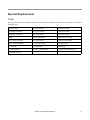
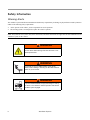
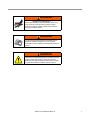
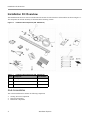
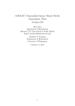
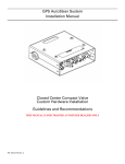
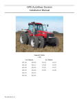
GPS AutoSteer System
Hardware Installation Manual
Supported Vehicles:
Cat Challenger
35
45
55
PN: 602-0214-01-A
LEGAL DISCLAIMER
Note: Read and follow ALL instructions in this manual carefully before installing or operating the AutoSteer system.
Note: Take careful note of the safety information in the Safety Information section and throughout this manual.
The manufacturer disclaims any liability for damage or injury that results from failure to follow the instructions and warnings
set forth herein.
Please take special note of the following warnings:
1. There is NO obstacle avoidance system included in the manufacturer’s product. Therefore, users must always have an
operator on the equipment when the AutoSteer system is in use to look for any obstacles including people, animals, trees,
ditches, buildings, etc.
2. During installation of the AutoSteer system and during the Calibration and Tuning processes the vehicle will pivot from
side to side on its tracks. Be sure that all people and obstacles are clear of the vehicle before installation, calibration and
tuning, or use of the AutoSteer system.
3. Use of the AutoSteer system is NOT permitted while the vehicle is on public roads or in public areas. Ensure that the system is OFF before driving on roads or in public areas.
ii
AutoSteer System
Special Requirements
Tools
This list consists of the tools required to complete the installation. The installer is assumed to have a complete set of common
installation tools.
Flat screwdriver
3/8" open wrench
15mm open wrench
#1 Phillips screwdriver
9/16" open wrench
17mm open wrench
#2 Phillips screwdriver
3/4" open wrench
21mm open wrench
Pliers
13/16" open wrench
17mm socket and ratchet
9/16" socket and ratchet
7/8" open wrench
21mm socket and ratchet
15/16" socket and ratchet
15/16" open wrench
Wire cutter small
Oil catch pan
Cleaning brush
Cleaning rags
Cable puller pole
Ten foot (3 meter) ladder
Tape measure (12ft minimum)
3/4" Torque wrench
Hardware Installation Manual
iii
Safety Information
Warning Alerts
The AutoSteer system installer and manufacturer disclaim any responsibility for damage or physical harm caused by failure to
adhere to the following safety requirements:
•
•
As the operator of the vehicle, you are responsible for its safe operation.
The steering system is not designed to replace the vehicle’s operator.
Note: Verify that all screws, bolts, nuts, hose connections, and cable connections are tight after the final installation of the
AutoSteer system on the vehicle.
WARNING
To avoid electrical shock hazards, remove the Roof Module
from the vehicle before driving under low structures or low
electrical power lines.
WARNING
Ensure that you are in a stable position on the vehicle
platform when installing or removing the Roof Rail and Roof
Module so you do not fall.
WARNING
To prevent accidental death or injury from being run over by
the vehicle, never leave the vehicle's operator chair with the
AutoSteer system engaged.
iv
AutoSteer System
WARNING
High-Pressure Fluid Hazard
Read the Owner’s Manual before installation. Wear hand
and eye protection while performing hydraulic system
maintenance. Relieve hydraulic system pressure before
servicing the hydraulic system.
WARNING
To understand the potential hazards associated with the
operation of AutoSteer equipment, read the provided
documentation before installing the GPS steering system on
a vehicle.
WARNING
To prevent the accidental engagement of AutoSteer and loss
of vehicle control while driving on roads, shut down the
AutoSteer system (exit the program). Never drive on roads
or in public areas with the AutoSteer system turned on.
Hardware Installation Manual
v
Caution Alerts
The AutoSteer system installer and manufacturer disclaim any responsibility for damage or physical harm caused by failure to
adhere to the following safety requirements:
CAUTION
The Roof Module must be removed when transporting or
driving the vehicle at speeds above 30 mph (48 km/h). The
Roof Module can possibly detach due to wind loads at
higher speeds.
CAUTION
The AutoSteer system does not detect obstacles in the
vehicle’s path. The operator must observe the path being
driven in order to avoid obstacles.
CAUTION
When engaged, the AutoSteer system controls only the
steering of the vehicle. The operator must control the speed
of the vehicle.
CAUTION
The AutoSteer system must be powered OFF when
installing or removing the Roof Module.
CAUTION
The Roof Module must always be firmly secured to the Roof
Rail using the hardware whenever the vehicle is in operation
to prevent the Roof Module from releasing from its bracket
and falling.
vi
AutoSteer System
Vehicle Requirements
The vehicle steering and hydraulic systems must be in good working order before installing the AutoSteer system. Check for
loose or worn parts. Drive the vehicle and confirm that it steers straight and the vehicle turns proportionally to the left and
right. Check the steering system hydraulic hoses and connections to ensure there are no oil leaks.
The vehicle electrical system and battery must be in good working order.
The vehicle should be fully cleaned before installing the AutoSteer system. A clean vehicle will improve the overall
installation and cable routing and will also reduce the chance for oil contamination when the hydraulic connections are
opened.
Hardware Installation Manual
vii
Important Information
This installation manual contains valuable information for servicing the AutoSteer system. After the installation is complete,
store this manual in a safe place for future reference.
Note: Verify that all screws, bolts, nuts, hose connections, and cable connections are tight after the final installation of the
AutoSteer system on the vehicle.
Technical Support
Refer to your owner's manual for technical support information.
Contact Information
Refer to your owner's manual for contact information.
Copyright © 2009 All Rights Reserved.
viii
AutoSteer System
Table of Contents
Chapter 1
Installation Overview....................................................................................... 1
Installation Kit Overview. . . . . . . . . . . . . . . . . . . . . . . . . . . . . . . . . . . . . . . . . . . . . . . . . . . . . . 2
Sub-Assemblies . . . . . . . . . . . . . . . . . . . . . . . . . . . . . . . . . . . . . . . . . . . . . . . . . . . . . . . . . . . 2
Pre-Installation Vehicle Tests . . . . . . . . . . . . . . . . . . . . . . . . . . . . . . . . . . . . . . . . . . . . . . . . . . 5
Installation Procedure Outline . . . . . . . . . . . . . . . . . . . . . . . . . . . . . . . . . . . . . . . . . . . . . . . . . . 7
Cable Diagram . . . . . . . . . . . . . . . . . . . . . . . . . . . . . . . . . . . . . . . . . . . . . . . . . . . . . . . . . . . . . 8
Chapter 2
Steering Valve Installation................................................................................ 9
Steering Valve Installation Procedure Overview. . . . . . . . . . . . . . . . . . . . . . . . . . . . . . . . . . . . 9
Prepare the Steering Valve for Installation . . . . . . . . . . . . . . . . . . . . . . . . . . . . . . . . . . . . . . . 10
Install the Steering Valve. . . . . . . . . . . . . . . . . . . . . . . . . . . . . . . . . . . . . . . . . . . . . . . . . . . . . 13
Hydraulic Hose Overviews . . . . . . . . . . . . . . . . . . . . . . . . . . . . . . . . . . . . . . . . . . . . . . . . . . . 15
Steering Valve Port Overview . . . . . . . . . . . . . . . . . . . . . . . . . . . . . . . . . . . . . . . . . . . . . . . 15
Hose Connection Overview . . . . . . . . . . . . . . . . . . . . . . . . . . . . . . . . . . . . . . . . . . . . . . . . . 16
Hydraulic Hose Connection Procedure . . . . . . . . . . . . . . . . . . . . . . . . . . . . . . . . . . . . . . . . . . 18
Attach Hoses to the Steering Valve . . . . . . . . . . . . . . . . . . . . . . . . . . . . . . . . . . . . . . . . . . . 18
Attach Hoses to the Vehicle Connections . . . . . . . . . . . . . . . . . . . . . . . . . . . . . . . . . . . . . . 23
Hydraulic Installation Checklist . . . . . . . . . . . . . . . . . . . . . . . . . . . . . . . . . . . . . . . . . . . . . . . 30
Chapter 3
SA Module Installation................................................................................... 31
SA Module Mounting Orientation . . . . . . . . . . . . . . . . . . . . . . . . . . . . . . . . . . . . . . . . . . . . . . 31
Mount the SA Module . . . . . . . . . . . . . . . . . . . . . . . . . . . . . . . . . . . . . . . . . . . . . . . . . . . . . . . 32
Chapter 4
Roof Module Installation ................................................................................ 35
Safety Notes . . . . . . . . . . . . . . . . . . . . . . . . . . . . . . . . . . . . . . . . . . . . . . . . . . . . . . . . . . . . . . . 35
Roof Rail Installation Procedure . . . . . . . . . . . . . . . . . . . . . . . . . . . . . . . . . . . . . . . . . . . . . . . 36
Chapter 5
Display Installation ........................................................................................ 41
Introduction . . . . . . . . . . . . . . . . . . . . . . . . . . . . . . . . . . . . . . . . . . . . . . . . . . . . . . . . . . . . . . . 41
Installation Procedure . . . . . . . . . . . . . . . . . . . . . . . . . . . . . . . . . . . . . . . . . . . . . . . . . . . . . . . 41
Chapter 6
Connecting System Cables............................................................................. 43
SA Module Harness . . . . . . . . . . . . . . . . . . . . . . . . . . . . . . . . . . . . . . . . . . . . . . . . . . . . . . . . . 43
SA Module Connection . . . . . . . . . . . . . . . . . . . . . . . . . . . . . . . . . . . . . . . . . . . . . . . . . . . . 43
Steering Valve Connections . . . . . . . . . . . . . . . . . . . . . . . . . . . . . . . . . . . . . . . . . . . . . . . . 44
Main Cable Harness . . . . . . . . . . . . . . . . . . . . . . . . . . . . . . . . . . . . . . . . . . . . . . . . . . . . . . . . . 45
Roof Module . . . . . . . . . . . . . . . . . . . . . . . . . . . . . . . . . . . . . . . . . . . . . . . . . . . . . . . . . . . . 45
SA Module Harness Connections . . . . . . . . . . . . . . . . . . . . . . . . . . . . . . . . . . . . . . . . . . . . 47
Main Cable Harness Connections Inside Cab . . . . . . . . . . . . . . . . . . . . . . . . . . . . . . . . . . . 49
Power Supply Connection . . . . . . . . . . . . . . . . . . . . . . . . . . . . . . . . . . . . . . . . . . . . . . . . . . . . 50
Cab Power Connection . . . . . . . . . . . . . . . . . . . . . . . . . . . . . . . . . . . . . . . . . . . . . . . . . . . . 50
Battery Power Connection . . . . . . . . . . . . . . . . . . . . . . . . . . . . . . . . . . . . . . . . . . . . . . . . . . 51
Chapter 7
Post-Installation Procedures and Information .................................................... 53
Create New Vehicle . . . . . . . . . . . . . . . . . . . . . . . . . . . . . . . . . . . . . . . . . . . . . . . . . . . . . . . . . 53
Hydraulic Leak Check . . . . . . . . . . . . . . . . . . . . . . . . . . . . . . . . . . . . . . . . . . . . . . . . . . . . . . . 53
ix
Chapter 8
x
Final Hardware Installation Checklist ............................................................... 55
Final Hardware Installation Checklist . . . . . . . . . . . . . . . . . . . . . . . . . . . . . . . . . . . . . . . . . 56
Hydraulic Installation Checklist . . . . . . . . . . . . . . . . . . . . . . . . . . . . . . . . . . . . . . . . . . . . . 56
AutoSteer Performance Checklist . . . . . . . . . . . . . . . . . . . . . . . . . . . . . . . . . . . . . . . . . . . . 56
GPS AutoSteer System
1
Installation Overview
The Installation Overview chapter information is provided in the following sections:
•
•
•
•
Installation Kit Overview
• Sub-Assemblies
• Steering Valve Kit Components
• Hose Kit Components
• Bracket Kit Components
Pre-Installation Vehicle Tests
Installation Procedure Outline
Cable Diagram
This installation guide describes the installation of the AutoSteer system on several models of Caterpillar track vehicles. The
AutoSteer installation kit PN: 188-0023-01 is used on the following models:
•
Caterpillar Track 35, 45, and 55 models
The vehicle specific sub-assemblies for the vehicle series are listed in Table 1-1.
Note: If you are installing an electric steering wheel actuator such as OnTrac II, skip the Steering Valve, SA Module, and
SA Module Harness installation information in this book and refer to your electric steering product manual for further
instructions.
Hardware Installation Manual
1
Installation Kit Overview
Installation Kit Overview
This Installation Kit Overview section is divided into sub-sections for each of the three sub-assemblies as shown in Figure 1-1.
The components in each sub assembly are described in the following sections.
Figure 1-1
Installation Kit Components (PN: 188-0023-01)
Table 1-1
Installation Kit Components (PN: 188-0023-01)
Item
Component
Part Number
1.
Steering Valve Kit - Cat
153-0007-01
2.
Hose Kit - Cat 35/45/55 (06/2004)
500-0022-02
3.
Brackets Kit Cat 35/45/55
152-0021-01
Sub-Assemblies
This vehicle installation kit contains the following components:
•
•
•
2
Steering Valve Kit Components
Hose Kit Components
Bracket Kit Components
AutoSteer System
Installation Kit Overview
Steering Valve Kit Components
Figure 1-2
Steering Valve Kit Components (PN: 153-0007-01)
Table 1-2
Steering Valve Kit Components (PN: 153-0007-01)
Item
Component
Part Number
1.
SA Module Harness - Cat
201-0162-02
2.
Assembly Kit - Common
200-0497-02
3.
SA Module Bracket Assembly
200-0190-01
4.
Valve Assembly - Cat
500-0010-02
5.
Cable Routing Hardware - Cat 35/45/55
200-0121-01
Hardware Installation Manual
3
Installation Kit Overview
Item
Component
Part Number
6.
Kit - RAM Mount Base with Screws
200-0508-01
8.
Attention Switch Off Label
603-0074-01
15.
SA Module Assembly - Wheeled
200-0206-01
16.
Temperature Sensor Kit - Cat
200-0119-01
Hose Kit Components
Figure 1-3
Hose Kit Components (PN: 500-0022-02)
Table 1-3
Hose Kit Components (PN: 188-0012-01)
Item
Component
Part Number
1.
Hose - 1/2” x 78” -8F 90 Degree x -8F ORFS
502-0006-02
2.
Hose - 1/2” x 78” -8F 90 Degree x -8M ORFS
502-0007-02
3.
Adapter, Run Tee ORFS F-M-M -8
506-0004-01
4.
Adapter, Run Tee ORFS F-M-M -6
506-0003-01
5.
Adapter, 45 Degree Elbow ORFS -8
506-0027-01
4
AutoSteer System
Pre-Installation Vehicle Tests
Item
Component
Part Number
6.
Adapter, Expander -8M x -6F ORFS
506-0061-01
7.
Tape Teflon 1/2” x 520”
511-0001-01
8.
Adapter, 90 Degree Elbow ORFS -8
506-0013-01
9.
Kit - Cable Tie Hose ID
200-0467-01
Bracket Kit Components
Figure 1-4
Bracket Kit Components (PN: 152-0021-01)
Table 1-4
Hose Kit Components (PN: 188-0012-01)
Item
Component
Part Number
1.
Display Bracket Assembly
200-0469-02
2.
Installation Guide
602-0214-01
3.
Washer, Flat M16x30x3
517-0007-01
Pre-Installation Vehicle Tests
The vehicle’s steering system must be in good working condition prior to the installation of the AutoSteer System. Verify the
existing steering system is operating correctly by performing the tests listed below in a wide open area.
Note: The steering system test requires a relatively large area. Ensure you have enough room to perform the test before
beginning.
Hardware Installation Manual
5
Pre-Installation Vehicle Tests
1. Drive the vehicle in a low gear and slowly turn the steering wheel all the way to the left. The vehicle should steer to the left
at a steadily increasing rate until it is making a sharp left turn.
2. Drive the vehicle in a low gear and slowly turn the steering wheel all the way to the right. The vehicle should steer to the
right at a steadily increasing rate until it is making a sharp right turn.
3. On flat terrain, drive the vehicle in a straight line in a low gear and release the steering wheel. The vehicle and steering
wheel should spring back to the center position and continue to drive straight after releasing the wheel without drifting
right or left.
Note: The vehicle and steering wheel should return to the center position and continue to drive straight after releasing
the wheel without drifting right or left.
4. Ask the vehicle driver or owner if they have experienced any vehicle steering problems. The operator should report no
steering problems.
If the vehicle passes the four tests, proceed with the AutoSteer system installation. If the vehicle fails one or more of the tests,
the steering system must be evaluated by a Caterpillar dealer and repaired if necessary.
Possible causes of steering problems:
•
•
Incorrect track tension
Hydraulic problem
Note: The Steering Valve controls the steering of the vehicle by changing the oil flow in the steer lines. The amount of
oil used to control the vehicle’s turn is very small. On some higher hour vehicles, it is possible that the vehicle may have
excessive internal leakage in the steering system that will not allow the Steering Valve to build up enough flow to control
6
AutoSteer System
Installation Procedure Outline
the steering. Though the AutoSteer system will not work, it is possible that manual steering work adequately in this
situation. If after installing the AutoSteer system the system does not steer and all troubleshooting procedures have been
followed, it may be necessary to have the system pressure and flow checked by an Caterpillar dealer service technician.
Installation Procedure Outline
1. Verify that all components have been received.
Note: Steps 2, 3, 4, and 8 are skipped if installing an electric steering actuator such as OnTrac II.
2. Install the Hydraulic Valve Assembly.
3. Install the Hydraulic Hoses.
4. Install the SA Module.
5. Install the Roof Rail on the cab roof.
6. Install the Roof Module on the Roof Rail.
7. Install the Monitor Mounting bracket in the cab
8. Install the SA Module harness.
9. Install the Main Cable harness.
10. Install the display using a RAM mount arm.
11. Connect the Main Cable harness to the display harness (Power, DB9 serial, RJ-45)
Note: Instructions for connecting the vehicle kit cables to the display can be found in the display owner’s manual.
12. Verify that all connectors are properly coupled and secured.
13. Start the vehicle and check for oil leaks.
14. Power ON the AutoSteer system.
15. Calibrate the vehicle.
16. Tune the vehicle.
17. Verify that the AutoSteer system has been installed properly and operates satisfactorily.
Hardware Installation Manual
7
Installation Procedure Outline
Cable Diagram
8
AutoSteer System
2
Steering Valve Installation
The Steering Valve Installation chapter information is provided in the following sections:
•
•
•
•
•
•
Steering Valve Installation Procedure Overview
Prepare the Steering Valve for Installation
Install the Steering Valve
Hydraulic Hose Overviews
• Steering Valve Port Overview
• Hose Connection Overview
Hydraulic Hose Connection Procedure
• Attach Hoses to the Steering Valve
• Attach Hoses to the Vehicle Connections
Hydraulic Installation Checklist
Note: Only technicians trained for hydraulic valve installations should perform the installation procedures in this chapter.
If your vehicle requires a hydraulic Steering Valve to be installed ensure a trained technician is available for the
installation.
Steering Valve Installation Procedure Overview
1. Prepare the Steering Valve for installation on the vehicle.
2. Install the Steering Valve on the vehicle.
3. Connect the six hoses between the Steering Valve and the vehicle.
4. Check for oil leaks.
5. Perform a manual functional test to confirm correct valve operation.
WARNING
High-Pressure Fluid Hazard
Read the Owner’s Manual before installation. Wear hand
and eye protection while performing hydraulic system
maintenance. Relieve hydraulic system pressure before
servicing the hydraulic system.
Hardware Installation Manual
9
Steering Valve Installation Procedure Overview
Prepare the Steering Valve for Installation
Prior to installing the Steering Valve onto the vehicle, an elbow and pressure transducer must be attached to the valve. Follow
the procedure below to prepare the valve for installation.
1. Place the Steering Valve on a flat surface, identify the pressure transducer port, and remove the protective port plug with a
pliers or flat screwdriver. See Figure 2-1.
Figure 2-1
Identify the Pressure Transducer Port
Pressure Transducer Port
10
AutoSteer System
Steering Valve Installation Procedure Overview
2. Wrap Teflon tape two times around the threaded side of the street elbow provided with the kit.
3. Attach the street elbow to the pressure transducer port and tighten with a 3/4" wrench. Point the elbow away from the valve
body as shown in Figure 2-2.
Figure 2-2
Street Elbow Attached
Street Elbow Attached
4. Wrap Teflon tape around the threads of the pressure transducer two times.
5. Attach the pressure transducer to the street elbow and tighten with a 3/4" wrench.
6. Tighten the pressure transducer until the pins match the connector so the wire will stay near the Steering Valve as shown in
Figure 2-3 and Figure 2-5.
Note: Verify the pins match up correctly. Do not force the connection.
Figure 2-3
Pressure Transducer Connectors
Pressure Transducer Pins
Pressure Transducer Connector
Hardware Installation Manual
11
Steering Valve Installation Procedure Overview
7. Attach the rubber gasket over the pressure transducer connector, then attach the pressure transducer connector to the
pressure transducer, and then secure the connection with the screw. Tighten the screw with a #1 Phillips screwdriver. See
Figure 2-4
Figure 2-4
Pressure Transducer Connector Detail
Note: The pressure transducer kit may come with an alternative rubber gasket. Either one can be used, but ensure that
one is installed. Failure to use the rubber gasket will allow moisture to get into the sensor and cause it to fail.
8. The Steering Valve is ready to install and should look similar to Figure 2-5.
Figure 2-5
Pressure Transducer Attached
Pressure Transducer and Cable Attached
12
AutoSteer System
Install the Steering Valve
Install the Steering Valve
The Steering Valve is installed on the inside of the vehicle’s frame ahead of the cab on the right side of the vehicle. Figure 2-6
shows the mounting location from the outside. The valve is attached directly to the frame.
Figure 2-6
Caterpillar 35, 45, and 55 Steering Valve Mounting Location
Steering Valve Mounting Location
1. Locate the two existing bolt holes from the inside of the of the right side frame under the engine area as shown in
Figure 2-7.
Figure 2-7
Steering Valve Mounting Location
Rear of the Vehicle is this Direction
Steering Valve Mounting
Bolt Holes
Hardware Installation Manual
13
Install the Steering Valve
2. Attach the Steering Valve with the two 3/8"x 4" bolts, washers, and nuts provided with the installation kit shown in
Figure 2-8. Tighten the bolts with a 9/16" wrench and 9/16" socket and ratchet.
Figure 2-8
Steering Valve Mounted
Mounting Bolts
3. The Steering Valve is now mounted.
14
AutoSteer System
Install the Steering Valve
Hydraulic Hose Overviews
Steering Valve Port Overview
The Steering Valve has six ports that need to be connected to the vehicle’s hydraulic system. The ports on the left side of the
valve are shown in Figure 2-9 and the ports on the bottom of the valve are shown in Figure 2-10.
Figure 2-9
Left Side Ports on Steering Valve
Figure 2-10 Bottom Ports on Steering Valve
Hardware Installation Manual
15
Install the Steering Valve
Table 2-1 shows a description and the fitting types and sizes of each of the ports on the Steering Valve.
Table 2-1
Steering Valve Port Functions and Fitting Sizes
Valve Label
Function
Fitting Type/Size
P
Pressure Line
-8 ORFS
T
Tank Line
-8 ORFS
STIN1
Steer Right from Orbitrol
-8 ORFS
STOUT1
Steer Right out to Vehicle
-8 ORFS
STIN2
Steer Left from Orbitrol
-8 ORFS
STOUT2
Steer Right out to Vehicle
-8 ORFS
Hose Connection Overview
Figure 2-11 shows an overview on how the hose connections are to be attached. The P port is teed into the main steering
pressure line. The T port is teed into the main steering tank line. The existing steer lines are disconnected from the vehicle
ports and the steer right line from the orbitrol is connected to the STIN1 port and the steer left line from the orbitrol is
connected to the STIN2 port. The STOUT1 port is then connected to the steer right port on the vehicle and the STOUT2 port is
connected to the steer left port on the vehicle.
Table 2-2 shows the list of hoses provided by the installation kit. The kit also provides colored cable ties. To ensure the correct
hose is attached to the correct port on both sides, attach the colored cable tie shown in the table to each end of the hose listed
prior to beginning the installation. It is also recommended that the existing hoses and ports on the vehicle are also labeled with
the colored cable tie that the new hoses will be attaching to before disconnecting the hoses to prevent a mix up.
The numbers in Figure 2-11 and Table 2-2 correspond to the Item Numbers for each hose provided in Table 1-2. If the number
has a “- #” after it, it means that there are multiple hoses with the same length and fittings.
16
AutoSteer System
Install the Steering Valve
Figure 2-11 Caterpillar 35, 45, and 55 Hose Connections
Table 2-2
Color Codes for Hydraulic Hoses
Valve Port Hose
Color
Item Number
Notes
P
Red
1-1
1/2" x 78" Hose -8 90 Deg ORFS x -8F ORFS
T
Green
1-2
1/2" x 78" Hose -8 90 Deg ORFS x -8F ORFS
STIN1
Blue
2-1
1/2" x 78" Hose -8 90 Deg ORFS x -8F ORFS
STIN2
Grey
2-2
1/2" x 78" Hose -8 90 Deg ORFS x -8F ORFS
STOUT1
Yellow
1-3
1/2" x 78" Hose -8 90 Deg ORFS x -8F ORFS
STOUT2
Orange
1-4
1/2" x 78" Hose -8 90 Deg ORFS x -8F ORFS
Hardware Installation Manual
17
Hydraulic Hose Connection Procedure
Hydraulic Hose Connection Procedure
Note: Due to the limited space in the Steering Valve port area, the hoses should be connected in the order provided by this
installation manual to reduce installation problems. Refer to the hose diagram in Figure 2-11 and Table 2-1 and Table 2-2
for information on connecting the correct hydraulic hose to the correct ports on the vehicle and Steering Valve.
WARNING
High-Pressure Fluid Hazard
Read the Owner’s Manual before installation. Wear hand
and eye protection while performing hydraulic system
maintenance. Relieve hydraulic system pressure before
servicing the hydraulic system.
Attach Hoses to the Steering Valve
1. Prepare the hydraulic hoses in the kit by attaching the proper colored cable ties to the ends of the hoses as described in
Table 2-2.
2. Attach the 90 degree connector of the Steer In Right hose to the STIN1 port on the Steering Valve.
3. Position the hose as shown in Figure 2-12 and tighten the connection with a 15/16" wrench.
Figure 2-12 STIN1 Hose Connection
STIN1 Connected
18
AutoSteer System
Hydraulic Hose Connection Procedure
4. Attach the 90 degree connector of the Steer In Left hose to the STIN2 port on the Steering Valve. Leave the connection
loose for the time being.
5. Attach the 90 degree connector of the Steer Out Right hose to the STOUT1 port on the Steering Valve. Leave the
connection loose for the time being.
6. Attach the 90 degree connector of the Steer Out Left hose to the STOUT2 port on the Steering Valve. Leave the connection
loose for the time being.
7. Adjust the angles of the 90 degree hose connections as shown in Figure 2-13 and then tighten the three connectors with a
15/16" wrench.
Figure 2-13 STIN2, STOUT1, STOUT2 Hose Connection
STIN2 Connected
STOUT2 Connected
STOUT1 Connected
8. To simplify the installation of the Tank hose, remove the solenoid from the left side of the valve with a 3/4" wrench.
Hardware Installation Manual
19
Hydraulic Hose Connection Procedure
9. Attach the 90 degree connector of the Tank hose to the T port on the Steering Valve. Point the hose connection downward
and tighten the connection with a 15/16" wrench as shown in Figure 2-14.
Figure 2-14 Tank Hose Connection
Solenoid Removed
Tank Hose
10. Reattach the solenoid valve and tighten only to 4-6 ft. lbs (5-8 nm) with a torque wrench. Verify that it is attached the
correct way (wires point towards the valve).
Note: Do not over tighten the nut or the solenoid could be damaged.
11. Assemble the temperature sensor assembly by attaching the temperature sensor to the probe. Tighten the connection with
17mm and 21mm wrenches. No Teflon is required for this connection as there is no oil pressure here.
20
AutoSteer System
Hydraulic Hose Connection Procedure
12. Attach the probe to the tee. Before attaching, the probe to the tee, wrap the threads two times with Teflon tape. Tighten the
connections with 3/4" and 17mm wrenches. See Figure 2-15 for the final assembly.
Figure 2-15 Temperature Sensor Assembly
Temperature Sensor
Probe
Tee
13. Attach the temperature sensor assembly to the P port on the Steering Valve. The temperature sensor should point upwards.
14. Connect the temperature sensor connector of the Steering Valve harness to the temperature sensor.
15. Attach a 90 -8 ORFS degree elbow to the end of the temperature sensor assembly tee and point the elbow downward.
Hardware Installation Manual
21
Hydraulic Hose Connection Procedure
16. Attach the 90 degree connector of the Pressure hose to the elbow. Tighten all connections with a 15/16" wrench. See
Figure 2-16 for an example of the final assembly.
Figure 2-16 Pressure Hose Connected
Steering Valve Harness
Temperature Sensor Connector
Temperature Sensor Assembly
90 Degree Elbow
Pressure Hose
22
AutoSteer System
Hydraulic Hose Connection Procedure
Attach Hoses to the Vehicle Connections
1. Locate the nuts and bolts holding the side panel to the right side of the vehicle between the tracks and the cab. See
Figure 2-17. Remove the nuts and bolts with a 1/2" socket and ratchet.
Figure 2-17 Side Panel
Remove Nuts and Bolts
Holding Panel
Note: Remove the nuts last as the studs will hold the panel from falling. When the nuts are removed be careful to not
allow the panel to fall.
Hardware Installation Manual
23
Hydraulic Hose Connection Procedure
2. Identify the ports and hoses that the Steering Valve will be connected to. See Figure 2-18.
Figure 2-18 Vehicle Hose Attachment Points
Tank Hose
(Hose Connects Directly
to Hydraulic Housing)
Steer Right Hose
Steer Left Hose
Pressure Hose
3. Mark the existing steer left and steer right hoses with the colored cable ties provided with the kit to prevent them from
being mixed up. The hose ends should be labeled the same color as the Steer In Left and Steer In Right hoses are. The
existing ports would be labeled the same color as the Steer Out Left and Steer Out Right hoses are colored.
24
AutoSteer System
Hydraulic Hose Connection Procedure
4. Disconnect the exiting Tank line with 13/16" and 3/4" wrenches. See Figure 2-19.
Figure 2-19 Tank Line Disconnected
5. Attach a -6 ORFS run tee to the existing fitting.
6. Attach the original hose to the end of the run tee.
7. Attach a -8 ORF to -6 ORFS hose adapter to the end of the Tank hose from the Steering Valve.
8. Attach the Tank hose to the tee port. See Figure 2-20
Figure 2-20 Attach Tank Hose
Original Tank Hose
Tank Hose Connection
-6 ORFS to -8 ORFS to
Hose Adapter
Run Tee
Hardware Installation Manual
25
Hydraulic Hose Connection Procedure
9. Tighten all hose connections and adapters with 13/16", 7/8", and 15/16" wrenches.
10. Disconnect the Orbitrol Steer Left hose from the diagnostic port fitting with 3/4" and 15/16" wrenches.
11. Attach the Steer In Left hose from the Steering Valve to the Orbitrol Steer Left hose. Tighten fittings with 7/8" and 15/16"
wrenches. See Figure 2-21.
Figure 2-21 Attach Steer In Left Hose
Orbitrol Steer Left Hose
Steer In Left Hose
Diagnostic Port Fitting
12. Disconnect the Orbitrol Steer Right hose from the pressure test port with 3/4" and 15/16" wrenches.
13. Attach the Steer In Right hose from the Steering Valve to the Orbitrol Steer Right hose. Tighten fittings with 7/8" and
15/16" wrenches. See Figure 2-22.
Figure 2-22 Attach Steer In Right Hose
Orbitrol Steer Right Hose
Steer In Right Hose
Diagnostic Port Fitting
26
AutoSteer System
Hydraulic Hose Connection Procedure
14. Attach the Steer Out Right hose to the steer right diagnostic port adapter. Tighten the hose with 3/4" and 15/16" wrenches.
15. Attach the Steer Out Left hose to the steer left diagnostic port adapter. Tighten the hose with 3/4" and 15/16" wrenches. See
Figure 2-23.
Figure 2-23 Attach Steer Out Hoses
Steer Left Diagnostic Port Fitting
Steer Out Left Hose
Steer Out Right Hose
Steer Right Diagnostic Port Fitting
16. Disconnect the existing Pressure line from the fitting at the pump with 3/4", 7/8", and 15/16" wrenches.
17. Attach a -8 ORFS run tee to the fitting.
18. Connect the existing pressure line to the end of the tee.
19. Attach a 90 degree -8 ORFS elbow to the tee port and point towards the front of the machine.
Hardware Installation Manual
27
Hydraulic Hose Connection Procedure
20. Attach the Pressure hose from the Steering Valve to the elbow and tighten all connections with a 15/16" wrench. See
Figure 2-24.
Figure 2-24 Pressure Hose Connected
Pressure Hose from Steering Valve
90 Degree Elbow
Existing Pressure Line
Run Tee
21. Organize and secure the hoses using cable ties in the side compartment so they cannot be damaged. See Figure 2-25.
Figure 2-25 Secure Hoses on Side
28
AutoSteer System
Hydraulic Hose Connection Procedure
22. Organize and secure the hoses under the vehicle going to the Steering Valve using heavy duty cable ties. Attach the hoses
to the existing metal lines. See Figure 2-26.
Figure 2-26 Secure Hoses to Bottom of Vehicle
Existing Metal Lines
Hardware Installation Manual
29
Hydraulic Hose Connection Procedure
Hydraulic Installation Checklist
Before starting the vehicle after installing the valve and hoses, verify the following to prevent damage to the vehicle or oil
spills.
1. The mounting bolts that secure the valve to the frame are tight.
2. The P hose is connected to correct port on Steering Valve and vehicle pressure port.
3. The T hose is connected to correct port on Steering Valve and vehicle tank port.
Note: If the Pressure and Tank hoses are reversed, the vehicle could possibly turn unexpectedly when the AutoSteer is
engaged. Double check these connections to make sure they are correct.
4. The STIN1 steer hose is connected to the correct port on the Steering Valve and attached to the steer right line from the
orbitrol.
5. The STIN2 steer hose is connected to the correct port on the Steering Valve and attached to the steer left line from the
orbitrol.
6. The STOUT1 steer hose is connected to correct port on the Steering Valve and the steer right port on the vehicle.
7. The STOUT2 steer hose is connected to correct port on the Steering Valve and the steer left port on the vehicle.
8. The Pressure Transducer has been installed and tightened.
9. The Temperature Sensor has been installed and tightened.
10. All other hose fittings are tight.
11. Checked that all hose and cables have been routed so they will not be damaged by moving parts or foreign objects.
WARNING
Prior to starting the vehicle, verify all people and equipment
are clear from around the vehicle and the AutoSteer system
is powered down. The vehicle could turn unexpectedly and
cause injury or death to bystanders.
Note: Before powering up the AutoSteer system, move the vehicle to a flat, wide open area where if the vehicle does
begin to spin, it will not damage anything.
30
AutoSteer System
3
SA Module Installation
The SA Module Installation chapter contains information in the following sections:
•
•
SA Module Mounting Orientation
Mount the SA Module
SA Module Mounting Orientation
The SA Module can also only be mounted in certain orientations. Figure 3-1 shows the correct mounting positions and
Figure 3-2 shows the improper mounting positions.
Figure 3-1
Correct SA Module Mounting Orientations
Figure 3-2
Incorrect SA Module Mounting Orientations
Hardware Installation Manual
31
Mount the SA Module
Mount the SA Module
Due to the variety of options available on vehicles and the possible configuration differences, it may be necessary to install the
SA Module in a location other than the example shown here. If an alternative location is required, choose a location where the
SA Module can be protected from damage from moving parts or crop debris and excessive moisture from weather and
cleaning equipment.
1. Locate the mounting bracket on the left, rear side of the vehicle. See Figure 3-3.
Figure 3-3
SA Module Mounting Location
SA Module Bracket
Mounting Location
32
AutoSteer System
Mount the SA Module
2. Start two of the SA Module mounting screws into the mounting bracket on the opposite side of the L-bracket.
3. Attach the SA Module bracket to the vehicle frame with a 3/8" x 1-1/2" bolt, flat washers, and nut from the installation kit.
See Figure 3-4. Tighten the bracket with a 9/16" wrench and 9/16"socket and ratchet.
Figure 3-4
SA Module Bracket Installed
Mounting Bolt
SA Module Mounting Screws
4. Attach the SA Module to the bracket with the connector facing the rear with the two other screws provided in the
installation kit. Tighten the screws with a #2 Philips screwdriver. See Figure 3-5.
Figure 3-5
SA Module Attached to the Bracket
Hardware Installation Manual
33
Mount the SA Module
34
AutoSteer System
4
Roof Module Installation
The Roof Module Installation chapter contains information in the following sections:
•
•
Safety Notes
Roof Rail Installation Procedure
Safety Notes
•
•
•
•
•
The AutoSteer system must be powered OFF when installing or removing the Roof Module.
The Roof Module must always be firmly secured to the Roof Rail using the hardware provided whenever the vehicle is in
operation to prevent the Roof Module from releasing from its bracket and falling.
The Roof Module must be removed when transporting the vehicle at speeds above 30 mph (48 km/h).
Ensure you are in a stable position on the vehicle platform when removing the Roof Module so that you do not fall or drop
the Roof Module.
Use a ladder to install the AutoSteer Roof Rail.
WARNING
Ensure that you are in a stable position on the vehicle
platform when installing or removing the Roof Rail and Roof
Module, so that you do not fall.
Hardware Installation Manual
35
Roof Rail Installation Procedure
Roof Rail Installation Procedure
1. Place the ladder as close as possible to the side of the cab.
2. Locate the two bolts on top of the cab shown in Figure 4-1. Remove the bolts with a 21mm socket and ratchet.
Note: Leave the rubber gasket on top of the roof.
Figure 4-1
Mounting Bolts Location
Mounting Bolt Locations
3. Place two M16 flat washers on both rubber gaskets. See Figure 4-2.
Figure 4-2
36
Place Flat Washers on Rubber Gasket
AutoSteer System
Roof Rail Installation Procedure
4. Place the Roof Rail on top of the washers and center it over the cab.
5. Attach the Roof Rail using the bolts removed earlier and tighten it securely with a 21mm socket and ratchet. See
Figure 4-3.
Figure 4-3
Attach Quick Attach Rail
6. Attach the three antennas to the proper antennas connections on the Roof Module. See Figure 4-4.
Note: Hand tighten the connections. Do not over tighten.
Figure 4-4
Attach the Antennas
Hardware Installation Manual
37
Roof Rail Installation Procedure
7. Place the Roof Module on the Roof Rail.
8. Remove the locking pin from the Roof Rail. See Figure 4-5.
Note: Press the button on the end of the handle to allow the pin to be removed.
Figure 4-5
Removing the Locking Pin
Locking Pin Button
9. Adjust the Roof Module position on the rail.
10. Re-insert the locking pin to lock the Roof Module onto the vehicle. See Figure 4-6.
Figure 4-6
Locking Pin Inserted
Locking Pin
38
AutoSteer System
Roof Rail Installation Procedure
11. The Roof Module is now installed. See Figure 4-6.
Figure 4-7
Roof Module Installed
Hardware Installation Manual
39
Roof Rail Installation Procedure
40
AutoSteer System
5
Display Installation
The Display Installation chapter contains information in the following sections:
•
•
Introduction
Installation Procedure
Introduction
This chapter provides the instructions for installing the RAM mount ball in the cab so that the user display can be attached
later. Refer to your display’s User Manual for instructions on installing the display.
Note: If the holes shown for mounting the display are being used by another piece of equipment, other mounting
locations can be used. However, for best performance and ease of use, use the holes shown in the installation manual.
Installation Procedure
1. Locate the accessory mounting bracket holes on the front right corner cab post. If necessary, remove any protective screws
or covers from the cab post. See Figure 5-1.
Figure 5-1
Identify the Bracket Mounting Holes
Mounting Holes for User
Display Bracket
Hardware Installation Manual
41
Installation Procedure
2. Attach the user display bracket to the mounting holes with the two longer M10 x 35mm bolts and washers that are included
with the installation kit. See Figure 5-2. Tighten the bracket with a 17mm socket and ratchet. The bracket should angle
back towards the side window.
Figure 5-2
Monitor Bracket Installed
Bracket Bolts
3. Attach the RAM mount ball to mounting bracket using the four 10-32x3/4 Phillips screws and lock nuts provided. Tighten
using a 3/8" wrench and #2 Philips screwdriver.
Figure 5-3
Mounted Display Bracket
RAM Mount Base
Note: Refer to the user display manual for the remaining user display specific installation instructions.
4. Replace the side panel between the tracks and the cab on the vehicle that was removed at the beginning of the installation.
42
AutoSteer System
6
Connecting System Cables
The Connecting System Cables chapter provides information in the following sections:
•
•
•
SA Module Harness
• SA Module Connection
• Steering Valve Connections
Main Cable Harness
• Roof Module
• SA Module Harness
• Main Cable Harness Connections Inside Cab
Power Supply Connection
• Cab Power Connection
• Battery Power Connection
SA Module Harness
SA Module Connection
1. Connect the SA Module harness to the SA Module. See Figure 6-1. Figure 6-1 shows an example SA Module not attached
to a vehicle and is to be used as a reference on how the SA Module harness connector attaches to the SA Module.
Figure 6-1
Connecting SA Module Connector
Bottom of SA Module
Cable Connector
Locking Mechanism in
Open Position (Latch)
Hardware Installation Manual
43
SA Module Harness
2. Close the cable connector locking mechanism as shown in Figure 6-2.
Figure 6-2
SA Module Connector (closed)
Locked Position Closed
Steering Valve Connections
1. Route SA Module harness’s 4-pin and 10 pin cable to the Steering Valve along the rear of the vehicle and then along the
right side with the newly installed hose connections.
2. Connect the 4-pin and 10-pin connectors to the Steering Valve jumper cable. See Figure 6-3.
Figure 6-3
Hydraulic Valve Connections
SA Module Harness Connectors
3. Neatly coil any excess cable and secure with cable ties.
4. Replace the side panel between the tracks and the cab on the vehicle that was removed at the beginning of the installation.
44
AutoSteer System
Main Cable Harness
Main Cable Harness
Roof Module
1. Attach the Main Cable Harness’s Roof Module connector and Ethernet connector to the Roof Module. See Figure 6-4.
Figure 6-4
Attach Data and RJ-45 Connector to Roof Module
Ethernet Connector
Roof Module Connector
2. Route the Roof Module data cable to the back of the cab. Secure the cable to the roof with a metal wire clamp and to the
underside of the roof with a cable tie. See Figure 6-5. Loosen the bolt on the roof with a 15mm socket and ratchet.
Figure 6-5
Route Cable to Left Rear Post
Metal Wire Clip
Cable Tie to Filter Hinge
Under the Lip of Cab
Hardware Installation Manual
45
Main Cable Harness
3. Route the cable down the left side cab post. There is nothing to attach the cable to the cab post on the bottom. To hold the
harness, a cable tie must be looped through the space between the fender and the cab and wrapped around the square tubing
below the fender.
4. Open the rear window and remove the wire access rubber grommet. See Figure 6-6.
Figure 6-6
Remove Rubber Grommet
5. Route the Main Cable Harness into the cab through the wire access port.
46
AutoSteer System
Main Cable Harness
SA Module Harness Connections
1. Route the Main Cable Harness’s SA Module data and SA Module power cables out the back window where the Roof
Module harness was routed in.
2. Connect the 12-pin data and 2-pin power connectors between the Main Cable Harness and the SA Module harness near the
SA Module. See Figure 6-7.
Figure 6-7
Connect SA Module Data and Power Connectors
2-Pin Power Connection
12-Pin Data Connection
3. If necessary cut a slot in the rubber grommet and then replace the rubber grommet and close the rear window.
4. Secure the Main Cable Harness cables to the rear of the vehicle. See Figure 6-8.
Figure 6-8
Route Cables on Back of Vehicle
Hardware Installation Manual
47
Main Cable Harness
5. Neatly coil excess cables and secure with cable ties. See Figure 6-9.
Figure 6-9
Coil and Secure Excess Cables
Coil Excess Cable and Secure
48
AutoSteer System
Main Cable Harness
Main Cable Harness Connections Inside Cab
Figure 6-10 shows the Main Cable Harness connections used inside the cab. Table 6-1 shows the functions of the Main Cable
Harness cab connectors. Refer to your display's User Manual for instructions on connecting the main cable harness
connections shown to the correct ports and harnesses on the user display and display cables.
Figure 6-10 Main Cable Harness Cab Connections
Table 6-1
Cab Main Cable Harness Connector Functions
Main Cable Harness Connector
Connector Function
DISPLAY ETH
Display Ethernet Port (RJ-45)
DISPLAY COMM
Display Communication Port (DB-9)
VEHICLE POWER
12 Volt Power Supplied by Display Harness
SAM POWER
Connected to SA Module Harness Power Connector
SAM DATA
Connected to SA Module Harness Data Connector
CAN IN
Not Used for this Installation
CAN OUT
Not Used for this Installation
Hardware Installation Manual
49
Main Cable Harness
Power Supply Connection
The following sub-sections describe basic instructions for connecting the AutoSteer system to available vehicle power
sources:
•
•
Cab Power Connection
Battery Power Connection
Note: Refer to your display user manual before connecting the AutoSteer system to vehicle power.
The AutoSteer Main Cable Harness must be connected to a 3-pin 12V power source. Your display user manual provides
specific instructions for connecting power to the AutoSteer system and specifies the appropriate vehicle power source.
Cab Power Connection
1. Locate the cab console right-side 12V power outlet. See Figure 6-11.
2. Use this 12V accessory power connector if the display manual specifies connecting to power inside the cab.
Figure 6-11 Cab 12V Power Outlet
Cab Power Connection
50
AutoSteer System
Main Cable Harness
Battery Power Connection
1. Locate the vehicle battery. See Figure 6-12.
2. Connect to the vehicle battery if the display manual specifies a direct battery connection.
Figure 6-12 Vehicle Battery Location
Note: A battery cable is provided with the AutoSteer system when a direct battery connection is required.
Hardware Installation Manual
51
Main Cable Harness
52
AutoSteer System
7
Post-Installation Procedures and Information
The Post-Installation Procedures and Information chapter provides information in the following sections:
•
•
•
Create New Vehicle
Hydraulic Leak Test
Calibration and Tuning Notes
Once the entire AutoSteer system, including the user display and display harnesses, have been installed on the vehicle, the
procedures and notes provided in this chapter must be followed to complete the installation and prepare the vehicle for full
AutoSteer capabilities.
Create New Vehicle
Once the entire system has been installed, the operator must first create a new vehicle profile. This configures the system so
that the user display can properly communicate with the various sensors and components on the vehicle. Follow the procedure
below to create a new vehicle.
1. Ensure that the vehicle is still in Park and/or the park brake is set to prevent the vehicle from moving.
2. Ensure the vehicle is off. Do not start the vehicle yet.
3. Power up the AutoSteer system.
4. Follow the instructions provided in the user display’s user manual to create a new vehicle.
Note: Do not start the vehicle until after the Hydraulic Leak Test has been performed on the vehicle. After the vehicle
has been created, shut down the AutoSteer system prior to starting the vehicle.
Hydraulic Leak Check
On completion of installing the entire AutoSteer system including the Roof Module and user display, the system needs to be
checked for leaks. Follow the procedure below to check for leaks.
1. Clear any bystanders away from the vehicle. If there is a hydraulic leak, they could be injured.
2. Put the vehicle into Park and/or set the park brake to prevent the vehicle from moving.
3. Turn the vehicle over for a few seconds and if the vehicle starts, immediately shut it down.
4. Walk around the vehicle and check all the hydraulic fittings that were opened. Look for any oil leaks.
5. Once all leaks have been repaired, or if none are found, start the vehicle again and let it run at a low idle.
Hardware Installation Manual
53
Hydraulic Leak Check
Note: If an oil leak is noticed during any part of this test, immediately shut down the vehicle and repair the leak.
Note: The entire vehicle will rotate on the tracks when the steering wheel is turned. Make sure the vehicle will not
strike anything or anyone before continuing. If necessary, move the vehicle to an open area.
6. Take the vehicle out of Park and/or remove the park brake. Turn the steering wheel manually to the right and left stops two
or three times to get any air out of the hoses.
7. Confirm that the vehicle rotates in the correct direction and that the vehicle steers the same as it did before the system was
installed.
8. Put the vehicle back into Park and/or reset the park brake. Shut down the vehicle, walk around it again, and check for any
hydraulic leaks.
9. Once the leaks have been repaired, or if none are found, start the vehicle again and let it run at a low idle.
10. Take the vehicle out of Park and/or remove the park brake. Move the vehicle to an open, flat area and leave the vehicle in
park.
11. Power up the AutoSteer display.
12. Power up the User display and navigate to the Hydraulic Valve window from the Steering Components window.
13. Command the vehicle to turn Right and then Left a few times. The vehicle should rotate in the direction it is commanded.
If the vehicle rotates in the wrong direction, the hoses were attached to the wrong ports on the valve and need to be
switched.
14. Power down the AutoSteer display, put the vehicle back into Park and/or reset the park brake, and shutdown the vehicle.
15. Once again check the vehicle for hydraulic leaks and repair any that are found.
54
AutoSteer System
8
Final Hardware Installation Checklist
This Final Hardware Installation Checklist contains the verifications steps necessary after the installation of the AutoSteer
system.
Note: The Final Hardware Installation Checklist is on the back of this page. Fill in the checklist after the installation is
complete. You should keep a copy of this checklist for future reference when servicing the AutoSteer system.
Customer Name: _______________________________________________________________________________________
Location/Address: _____________________________________________________________________________________
Contact Information ____________________________________________________________________________________
Machine Model: _________________________________ Year: _________ Serial #: _______________________________
AutoSteer Installation Kit Part Number: ____________________________________________________________________
NOTES
____________________________________________________________________________________________________
____________________________________________________________________________________________________
____________________________________________________________________________________________________
____________________________________________________________________________________________________
____________________________________________________________________________________________________
____________________________________________________________________________________________________
____________________________________________________________________________________________________
____________________________________________________________________________________________________
____________________________________________________________________________________________________
____________________________________________________________________________________________________
____________________________________________________________________________________________________
____________________________________________________________________________________________________
Name of Installer: __________________________________________________ Date Installed:_______________________
Hardware Installation Manual
55
Final Hardware Installation Checklist
Final Hardware Installation Checklist
1. User Display Bracket Installed and all fasteners are tight.
2. User Display Installed.
3. Roof Rail is installed and all fasteners are tight.
4. SA Module is installed and all fasteners are tight.
5. All cable ends are connected.
6. All cables are secured with cable ties.
Hydraulic Installation Checklist
1. Steering Valve is installed and all fasteners are tight.
2. All hose fittings are tight.
3. All hoses are routed and secured with cable ties.
4. Vehicle has been checked for hydraulic leaks after the installation.
5. Manual steering is normal after the AutoSteer installation.
AutoSteer Performance Checklist
1. Complete AutoSteer system calibration.
2. Complete AutoSteer system tuning.
3. Line acquisition performance is good.
4. On-line steering performance is good.
5. Manual override (kick-out) is working.
6. Temperature sensor is working.
7. Record Temperature Sensor reading after idling engine for 10 minutes:
8. Check that Manual Steering speed is the same as before the installation.
56
AutoSteer System
Temp.___________