1
User Manual
March 2010
Revision 1.3
Galeo
Point – of - Sale
Hardware System
Copyright 2008 ~ 2010
All Rights Reserved
Manual Version 1.3
The information contained in this document is subject to change without notice.
We make no warranty of any kind with regard to this material, including, but not limited to, the
implied warranties of merchantability and fitness for a particular purpose. We shall not be liable
for errors contained herein or for incidental or consequential damages in connection with the
furnishing, performance, or use of this material.
This document contains proprietary information that is protected by copyright. All rights are
reserved. No part of this document may be photocopied, reproduced or translated to another
language without the prior written consent of the manufacturer.
TRADEMARK
Intel®, Pentium® and MMX are registered trademarks of Intel® Corporation. Microsoft® and
Windows® are registered trademarks of Microsoft Corporation.
2
Safety
IMPORTANT SAFETY INSTRUCTIONS
1. To disconnect the machine from the electrial power supply, turn off the power switch and
remove the power cord plug from the wall socket. The wall socket must be easily
accessible and in close proximity to the machine.
2. Read these instructions carefully. Save these instructions for future reference.
3. Follow all warnings and instructions marked on the product.
4. Do not use this product near water.
5. Do not place this product on an unstable cart,stand,or table.The product may fall, causing
serious damage to the product.
6. Slots and openings in the cabinet and the back or bottom are provided for ventilation;to
ensure reliable operation of the product and to protect it from overheating. These openings
must not be blocked or covered.The openings should never be blocked by placing the
product on a bed, sofa, rug, or other similar surface.This product should never be placed
near or over a radiator or heat register,or in a built-in installation unless proper ventilation is
provided.
7. This product should be operated from the type of power indicated on the marking label.If
you are not sure of the type of power available, consult your dealer or local power
company.
8. Do not allow anything to rest on the power cord. Do not locate this product where persons
will walk on the cord.
9. Never push objects of any kind into this product through cabinet slots as they may touch
dangerous voltage points or short out parts that could result in a fire or electric shock.
Never spill liquid of any kind on the product.
CE MARK
This device complies with the requirements of the EEC directive 2004/108/EC
with regard to “Electromagnetic compatibility” and 2006/95/EC “Low Voltage
Directive”.
FCC
This device complies with part 15 of the FCC rules. Operation is subject to the following two
conditions:
(1) This device may not cause harmful interference.
(2) This device must accept any interference received, including interference that
may cause undesired operation.
3
CAUTION ON LITHIUM BATTERIES
There is a danger of explosion if the battery is replaced incorrectly. Replace only with the same
or equivalent type recommended by the manufacturer. Discard used batteries according to the
manufacturer’s instructions.
LEGISLATION AND WEEE SYMBOL
2002/96/EC Waste Electrical and Electronic Equipment Directive on the treatment,
collection, recycling and disposal of electric and electronic devices and their
components.
The crossed dustbin symbol on the device means that it should not be disposed of with other
household wastes at the end of its working life. Instead, the device should be taken to the
waste collection centers for activation of the treatment, collection, recycling and disposal
procedure.
To prevent possible harm to the environment or human health from uncontrolled waste
disposal, please separate this from other types of wastes and recycle it responsibly to promote
the sustainable reuse of material resources.
Household users should contact either the retailer where they purchased this product, or their
local government office, for details of where and how they can take this item for
environmentally safe recycling.
Business users should contact their supplier and check the terms and conditions of the
purchase contract.
This product should not be mixed with other commercial wastes for disposal.
4
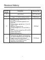
Revision History
Revision
Number
Description
Revision Date
1.0
Initial release
2007 December
1.1
Chapter 7.2.3 default setting correction
2008 January
1.2
1.3
• Drivers of B78 M/B updated from v1.0 to
v2.2 (page 11~21)
• M/B Layout of B78 M/B updated to v2.2.
(page 36)
• Jumper settings updated from v1.0 to v2.2
(page 37~42)
• MB photos updated to v2.2.
• I/O Port change line-in / line-out to MIC-in /
line-out
• HDD Connector changed from IDE to SATA.
• Updated specification
• Updated optional items
Update for new VFD module:
• configuration by software (no dip-switches)
• non volatile EEPROM to store configuration
• supports user defined character set
• software utilities to configure VFD, define
character set and update firmware
• Added dimensional drawings
5
2009 April
2010 March
Table of Contents
1.
Item Checklist ..................................................................................................................7
1.1. Standard Items..........................................................................................................7
1.2. Optional Items...........................................................................................................8
2.
System View.....................................................................................................................9
2.1. Front View.................................................................................................................9
2.2. Back View .................................................................................................................9
2.3. Side View................................................................................................................10
2.4. I/O View ..................................................................................................................10
3.
Driver Installation .......................................................................................................... 11
3.1. Driver List................................................................................................................11
3.2. Chipset Driver Installation .......................................................................................11
3.3. USB 2.0 Driver Installation......................................................................................13
3.4. VGA Driver Installation............................................................................................16
3.5. Audio Driver Installation ..........................................................................................17
3.6. 17
3.7. ELO Touch Driver Installation .................................................................................18
3.8. USB VFD Driver Installation....................................................................................21
3.9. 10/100/1000Mb LAN Driver Installation ..................................................................22
4.
Peripherals Installation .................................................................................................23
4.1. Accessing to the I/O................................................................................................23
4.2. MSR Installation......................................................................................................24
4.3. Cash Drawer Installation.........................................................................................25
5.
System Disassembly .....................................................................................................27
5.1. Replacing the HDD .................................................................................................27
5.2. Replacing the Slim VFD..........................................................................................28
5.3. Replacing the Mainboard ........................................................................................29
5.4. To Separate the Panel from the Stand ....................................................................31
5.5. Replacing Inverter Board, Touch Screen Board & MSR Board ...............................32
6.
Specification ..................................................................................................................34
7.
Jumper Settings.............................................................................................................36
7.1. Connectors .............................................................................................................37
7.2. Jumper settings ......................................................................................................38
8.
BIOS Settings.................................................................................................................43
8.1. BIOS Setup Utility ...................................................................................................43
8.2. Starting the BIOS Setup..........................................................................................43
8.3. When a Problem Occurs.........................................................................................43
8.4. BIOS Main Menu ....................................................................................................43
9.
Dimensions ....................................................................................................................45
10. Customer Display Command Settings.........................................................................47
6
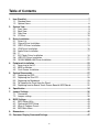
1. Item Checklist
Take the system unit out of the carton. Remove the unit from the carton by holding it by the
foam inserts. The following contents should be found in the carton:
1.1. Standard Items
a. Driver CD
b. System
c. Power Cable
d. Power adapter
e. COM port cables (4)
7
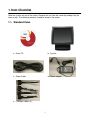
1.2. Optional Items
a. Magnetic Card reader
b. iButton Dallas reader
c. Magnetic Card +
iButton Dallas reader
d. RFID reader
e. Magnetic Card Reader +
Biometric Reader (fingerprint)
8
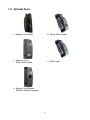
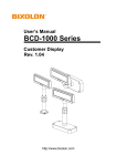
2. System View
2.1. Front View
Power LED
USB
Power Button
2.2. Back View
Customer Display
(VFD)
MSR
dummy
door
Ventilation slots
9
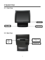
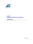
2.3. Side View
Tilt Angle 65˚ ~ -25˚
Ventilation slots
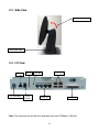
2.4. I/O View
LAN
MIC in
DC Connector
Cash
Drawer
USB (4)
Line out
COM (4)
Parallel
Note: The maximum current that can be drawn from each COM port is 500 mA.
10
3. Driver Installation
3.1. Driver List
Folder/File
File Description
<CD>:\Galeo\Galeo.htm
Galeo Driver List
<CD>:\COMMON\INTEL\Chipset\i8xx
Chipset Driver
<CD>:\COMMON\INTEL\USB20
USB 2.0 Driver
<CD>:\COMMON\INTEL\VGA\i85x
VGA Driver
<CD>: COMMON\ELO_Touch
<CD>:\COMMON\Ac97_codec\Realtek\ALC202A
ELO Touch Driver
Audio Driver
<CD>:\ Common\Lan_driver\Realtek_PCI
10/100/1000MB LAN Driver
<CD>:\ Common\USB2COM\PL-2303HX
USB-VFD PL2303 Driver
-The following procedures are for Windows 2000/XP, other platforms are similar.
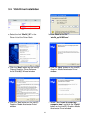
3.2. Chipset Driver Installation
a. Double-click
“infinst_enu_6.0.1.1002.exe” on the
My computer window.
b. Click the “Next” button on the Welcome
window.
11
c. Click the “Yes” button on the License
Agreement window.
d. Click the”Next” button on the Readme
Information window.
e. Click the “Finish” button and restart your system.
12
3.3. USB 2.0 Driver Installation
OS Requirements
OS
USB 2.0 requirements
Windows XP
USB 2.0 drivers are provided in Service Pack 1 (SP1) for Windows XP,
which is available through Windows Update.
Windows 2000
USB 2.0 drivers are available through Windows Update or Service Pack
4.
Windows 98SE/Me USB 2.0 drivers are available on the Intel developer site.
Windows 98
(Retail)
Developers and OEMs should contact Orange Ware. For end-users, if
your device does not ship with Windows 98 drivers, contact your device
or system manufacturer. If USB 2.0 drivers are not available, your device
will operate at USB 1.1 speeds
Linux
USB 2.0 support is available in kernel 2.4.19 or later development
kernels, or in the 2.4.19 or later production kernel. More information.
13
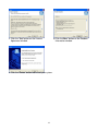
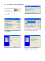
a. Right click “My Computer” on the
desktop and select “properties”
b. Select “Hardware””Device
Manager” on system properties
c. Select ”Other Devices” “Universal Serial Bus (USB) Controller” ”Properties” on
Device Manager
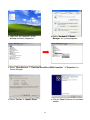
d. Select “Device” “Update Driver”
e. Click the ”Next” button on the welcome
window.
14
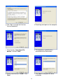
f. Select “Search for a suitable…”and
click the “Next” button on the Install
Hardware Device Drivers window
g. Select “Specify a location” and click
the “Next” button on the Locate Driver
Files window.
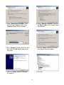
h. Press “Browse” to select the driver and
then click the “OK” button to go to the
next page
i. Click the “Next” button on the Driver
Files Search Results window.
j. Click the “Finish” button to complete
this process.
k. Finished.
15
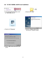
3.4. VGA Driver Installation
a. Select the link “Win2K_XP” in the
Driver List of the Driver Bank.
b. Click “Run” to run the
“win2k_xp141950.exe”.
c. Click the “Next” button on the Intel(R)
Chipset Graphics Driver SoftwareInstall Shield(R) Wizard window.
d. Click the “Next” button on the Intel(R)
Graphics Media Accelerator Driver
window.
e. Click the “Yes” button on the Intel(R)
Graphics Media Accelerator Driver
window.
f. Select “Yes, I want to restart my
computer now” and click the “Finish”
button on the Intel(R) Graphics Media
Accelerator Driver window.
16
3.5. Audio Driver Installation
3.6.
a. Double-click “A3.71” on the My Computer
window.
b. Double-click “wdm_a371.exe” on the
My Computer window.
c. Click “Next” button on the Realtek AC’97
Audio Setup window.
d. Click “Yes” button on the Digital
Signature Not Found window.
e. Click “Finish” button on the Realtek
AC’97 Audio Setup window.
17
3.7.
ELO Touch Driver Installation
a. In the “ELO” section, click on
“Windows”.
b. Click “OK”.
c. Click “Unzip“ to extract the driver to the
specified folder.
d. Finished unzipping. Click “OK”.
e. Click “Next”.
f. Check the box “Install Serial
Touchscreen Drivers” and click
“Next”.
18
g. Click “Yes” to accept the End User
License Agreement
h. Examining serial ports on the computer
i. Check the box “Auto-detect Elo
devices” and click “Next”.
j. The computer is searching for a
connected to Elo Touchscreen
k. Touchscreen found on “COM5”. Click
“Next”.
l. Click “Next” to complete the driver
installation
19
m. Driver is installing
n. The driver installation and setup are
now complete. Click “Finish” to start
the touchscreen calibration.
o. Follow the instructions on the screen to
calibrate the Touchscreen.
p. Verify that the touchscreen is working
correctly by moving your finger on the
screen. The mouse cursor should
follow your finger. Finally, touch the
green checkmark to save the
calibration settings and exit the
program
20
3.8. USB VFD Driver Installation
a. Click the “PL-2303 Driver Installer” on
the “Win98-ME_2X_XP_2003” window
b. Click the “Next” button on the
Welcome window
c. Click the “Finish” button on the
InstallShield window
The driver will be installed on the first free COM port in the system.
In general this will be COM7, but the actual number may be different, depending on your
system configuration.
You can check the actual COM port used by the customer display in the Windows Device
Manager."
21
3.9. 10/100/1000Mb LAN Driver Installation
a. In the Realtek RTL8110 section, click
on “Win9X, ME, 2K, XP”
b. Double-click “v709”
c. Double-click “Setup.exe”
d. Click the “Finish” button on the
Maintenance Complete window.
e. Click the “OK” button and restart your
system.
22
4. Peripherals Installation
4.1. Accessing to the I/O
a. Loosen the thumb screws (2) to remove
the front side stand cover.
b. Loosen the thumb screws (2) and
disconnect the cable to release Main
board module.
c. Lift the Main board module up to access
to the I/O
23
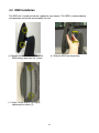
4.2. MSR Installation
The MSR unit is tested and can be supplied at your request. This MSR is removed during
transportation and can be connected by the user.
a. Remove the screws (2) to release the
MSR dummy door from the system.
b. Slide the MSR into the position
c. Fasten it to the display housing by
tightening the screws (2).
24
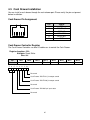
4.3. Cash Drawer Installation
You can install a cash drawer through the cash drawer port. Please verify the pin assignment
before installation.
Cash Drawer Pin Assignment
6
Pin
1
2
3
4
5
6
1
Signal
GND
DOUT bit0
DIN bit0
12V / 19V
DOUT bit1
GND
Cash Drawer Controller Register
The Cash Drawer Controller use one I/O addresses to control the Cash Drawer.
Register Location: 4B8h
Attribute: Read / Write
Size: 8bit
BIT
Attribute
7
X
6
X
5
X
BIT7
4
3
X
2
BIT6
Reserved
1
BIT5
BIT4
Read
BIT3
Reserved
0
X
Reserved
Cash Drawer “DOUT bit1” pin output control
Cash Drawer “DOUT bit0” pin output control
Reserved
Cash Drawer “DIN bit0” pin input status
Reserved
25
BIT2
BIT1
Write
BIT0
Reserved
Bit 7: Reserved.
Bit 6: Reserved.
Bit 5: Reserved.
Bit 4: Cash Drawer “DIN bit0” pin input status.
= 1: the Cash Drawer closed or no Cash Drawer.
= 0: the Cash Drawer opened.
Bit 3: Reserved.
Bit 2: Cash Drawer “DOUT bit0” pin output control.
= 1: Opening the Cash Drawer
= 0: Allow closing the Cash Drawer
Bit 1: Cash Drawer “DOUT bit1” pin output control.
= 1: Opening the Cash Drawer
= 0: Allow closing the Cash Drawer
Bit 0: Reserved
Note: Please follow the Cash Drawer control signal design to control the Cash Drawer
Cash Drawer Control Command Example
Use Debug.EXE program under DOS or Windows98
Command
Cash Drawer
O 4B8 04
Opening
O 4B8 00
Allow to closing
Set the I/O address 4B8h bit2 =1 for opening the Cash Drawer by “DOUT bit0” pin control.
Set the I/O address 4B8h bit2 = 0 to allow closing Cash Drawer.
Command
Cash Drawer
I 4B8
Check status
The I/O address 4B8h bit4 =1 means the Cash Drawer is closed or no Cash Drawer.
The I/O address 4B8h bit4 =0 means the Cash Drawer is open.
26
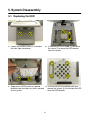
5. System Disassembly
5.1. Replacing the HDD
SATA Cable
a. Loosen the thumb screws (2) to remove
the front side stand cover.
b. Disconnect the SATA cable (1) and loose
the screw (1) to loose the HDD bracket
from the system.
Hooks
c. Separate the HDD bracket as upward
direction from the hooks as circles marked
on the system.
d. Turn the rear of HDD bracket front and
remove the screws (4) to unfasten the HDD
from the HDD bracket.
27
5.2. Replacing the Slim VFD
a. Loosen the thumb screws (2) to remove
the stand back cover.
b. Remove the screws (2) to release the
VFD from the system
c. Disconnect the cable to replace the VFD
28
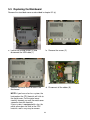
5.3. Replacing the Mainboard
Remove the stand back cover as described in chapter 5.2 (a)
a. Loosen the thumb screws (2) and
disconnect the USB cable (1)
b. Remove the screws (2)
c. Remove the metal cover to access the
Mainboard.
d. Disconnect all the cables (9)
NOTE: if you have a fan-less system, the
heat-pad on the CPU heatsink will stick to
the metal cover. Pull the metal cover
carefully towards you until the metal cover
separates from the heatsink.
If your system is equipped with a fan, the
metal cover does not stick to the CPU
heatsink, and is very easy to remove.
29
e. Pull the thumbscrew (1) in the direction as
shown by the arrow to release the main
board tray from the system
f. Remove the hex screws (2) to replace the
Mainboard
g. Remove the screws (6) to replace the main board from the tray
30
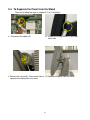
5.4. To Separate the Panel from the Stand
Please first follow the steps in chapter 5.2 (a), 5.3(a)(b)(c)
a. Disconnect the cables (5)
b. Remove the hinge covers(2) one from
each side
c. Remove the screws(6), 3 from each side to
separate the display from the stand
d. Separate the panel from the stand
31
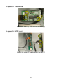
5.5. Replacing Inverter Board, Touch Screen Board & MSR Board
Please first follow the steps in chapter 5.2 (a), 5.3(a)(b)(c), 5.4
a. Remove the screws (4)
b. Remove the screws(2) to remove the MSR
cover
c. Remove the screws(1) then remove the
display cover from the panel
d. Now you can access to the Inverter board,
touch board, and the MSR board
To replace the Inverter Board
Remove the screws (2) and disconnect the cables (3).
32
To replace the Touch Board
Remove the screws (2) and disconnect the cables(2).
To replace the MSR Board
Remove the screws (2) and disconnect the cable (1)
33
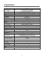
6. Specification
Motherboard
CPU Support
Chipset
System Memory
Graphic Memory
LCD Panel
LCD Size
Brightness
Maximal Resolution
Touch Screen Type
Tilt Angle
Storage
HDD
Flash Memory
Expansion
Mini-PCI Socket
I/O
Front I/O
USB
Power Switch
Base Rear I / O
USB
Serial/COM
Parallel
LAN (10/100/1000)
Cash Drawer
Microphone-in
Line-out
Control/Indicator
Power Button
Indicator LED
Power
Power Adapter
B78
ULV Celeron M 1.0G zero cache
Celeron M 1.5G (socket CPU)
Intel 852GM + ICH4
2 x S.O.DIMM, DDR, 400 MHz, up to 2 GB
Shared system memory up to 64MB
15" TFT
250 - 350 cd / m²
1024 x 768
Resistive
-25° ~ 65°
slim HDD bay x1 (SATA interface )
optional compact flash board
1
1(V2.0)
1
4 (V2.0) (one USB occupied by front USB connector)
COM 1/COM2 standard RS-232,
COM3/COM4 pin 9 with 5V/12V by jumper
1 x D-sub 25-pin connector
1 x RJ45
12V /19V
1
1
1
1 x power LED
90W
34
Peripherals
Customer Display
Magnetic Card Reader
iButton Dallas Reader
Magnetic Card + iButton
Dallas Reader
RFID Reader
Biometric Reader
(fingerprint) +
Magnetic Card Reader
Environment
Operating Temperature
Storage Temperature
Operating Humidity
Storage Humidity
OS Support
slim type VFD (USB interface)
3 Track (keyboard or RS232 interface)
Keyboard and RS232 interface
Keyboard interface (Magnetic Card reader)
Keyboard and RS232 interface (iButton Dallas reader)
USB interface
USB interface (Biometric reader)
PS/2 interface (Magnetic Card Reader)
5°C ~ 35°C ( 41°F ~ 95°F )
-20°C ~ 55°C (-4°F ~ 140°F)
20% - 80% RH non condensing
20% - 85% RH non condensing
Windows XP, WEPOS, XP Embedded, XP Professional for
Embedded, WIN 2000/NT 4.0
35
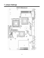
7. Jumper Settings
B78 V2.2 Motherboard
36
7.1. Connectors
Connector
Function
BAT1
CMOS Battery Base ( Use CR2023)
CN1
Audio Line Out
CN2
Audio MIC In
CN3
Internal Power Switch
CN4
Speaker & MIC Connector
CN9
CD-IN Connector
CN11
Power Connector For 3.5" HDD
CN13
COM5 for Touch
CN15
CPU FAN Connector
CN16
Hardware Reset
CN18
USB2
CN19
LCD Interface Connector
CN20
Inverter Connector
CN21
Card Reader Connector
CN22
System FAN Connector
CN23
IrDA Connector
CN24
FT Status Interface
CN26
Internal Power In Connector
CN27
Internal LPT Connector
CN28
Internal PCI Reset Output Connector
IED1
Secondary IDE Connector (Pitch = 2.0mm)
PRN1
Parallel Port
PWR1
+19V Power Adaptor
RJ11_1
Cash Drawer Connector
RJ45_1
LAN (On Board)
RJ45_2
COM1, COM2, COM3, COM4
SATA1
SATA Connector
USB1
USB3, USB4
USB2
USB5, USB6
JP1
VGA Port
JP2
VGA Power
37
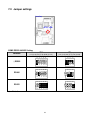
7.2. Jumper settings
Location
JP10 / JP9
COM2 RS232/485/422 Setting
Function
JP10
JP9
(1-2) (3-4) (5-6) (7-8) (9-10) (11-12)
(1-2) (3-4) (4-6) (5-7) (7-8) (9-10)
1 3 5 7 9 11
1 3 5 7 9
2 4 6 8 10 12
2 4 6 8 10
1 3 5 7 9 11
1 3 5 7 9
2 4 6 8 10 12
2 4 6 8 10
1 3 5 7 9 11
1 3 5 7 9
2 4 6 8 10 12
2 4 6 8 10
◎RS232
RS485
RS422
◎ = Default
38
COM3 & COM4 Power Setting
JP3
Function
(1-2) (3-4) (5-6) (7-8) (9-10) (11-12)
Location
1 3 5 7 9 11
◎RI
2 4 6 8 10 12
1 3 5 7 9 11
COM3
Pin 9 (DB9)
Location
+5V
2 4 6 8 10 12
1 3 5 7 9 11
+12V
2 4 6 8 10 12
1 3 5 7 9 11
◎RI
2 4 6 8 10 12
COM4
Pin 9 (DB9)
1 3 5 7 9 11
+5V
2 4 6 8 10 12
1 3 5 7 9 11
+12V
2 4 6 8 10 12
◎ = Default
39
JP3
Cash Drawer Power Setting
JP4
Function
(1-2) (3-4) (5-6)
Location
1 3 5
+12V
2 4 6
1 3 5
JP7
◎+19V
JP4
2 4 6
◎ = Default
LCD ID Setting
Panel #
Resolution
LVDS
Bits
JP7
Channel
(1-2) (3-4) (5-6) (7-8)
1 3 5 7
1
640
x
480
18
Single
2 4 6 8
1 3 5 7
2
800
x
600
18
Single
2 4 6 8
1 3 5 7
3
1024
x
768
18
Single
2 4 6 8
1 3 5 7
4
1280
x
1024
24
Dual
2 4 6 8
40
Panel #
Resolution
LVDS
Bits
JP7
Channel
(1-2) (3-4) (5-6) (7-8)
1 3 5 7
5
1024
x
768
24
Single
2 4 6 8
1 3 5 7
6
800
x
600
24
Single
2 4 6 8
1 3 5 7
7
800
x
600
18
Single
2 4 6 8
1 3 5 7
8
800
x
600
18
Single
2 4 6 8
1 3 5 7
9
1024
x
768
24
Single
2 4 6 8
1 3 5 7
10
1440
x
900
24
Dual
2 4 6 8
1 3 5 7
11
1280
x
1024
24
Dual
2 4 6 8
1 3 5 7
12
1440
x
900
18
Dual
2 4 6 8
41
Power Mode Setting
Function
JP6 (1-2)
◎ATX Power
AT Power
Location
CMOS Operation Mode
Function
JP8 (1-2)
◎CMOS Normal
JP13
CMOS Reset
JP8
JP14
USB Path Setting
Function
JP6
JP14 (1-2)
To Docking
◎To MB
◎ = Default
42
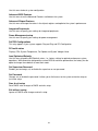
8. BIOS Settings
8.1. BIOS Setup Utility
The BIOS setup defines how the system is configured. You need to run this program the first time you
configure this product. You may need to run it again if you change the configuration.
You need to connect a PC keyboard to the keyboard connector to run the BIOS setup utility.
8.2. Starting the BIOS Setup
Turn on or reboot this product.
Press the DEL key immediately after the product is turned on, or press the DEL key when the following
message is displayed during POST (the Power on Self-Test)
Press DEL to enter SETUP.
The main menu of the BIOS setup is displayed.
If the supervisor password is set, you must enter it here.
8.3. When a Problem Occurs
If, after making and saving system changes with the Setup utility, you find that this product no longer
boots, start the BIOS setup and execute the following
Load Optimized Defaults
8.4. BIOS Main Menu
When the BIOS Main Menu is displayed, the following items can be selected. Use the arrow keys to
select items and the Enter key to accept and enter the sub-menu.
Note: The BIOS setup menus shown in this section are for reference only and may not exactly match
the items of your BIOS version.
.
Standard CMOS Features
43
Use this menu for basic system configuration.
Advanced BIOS Features
Use this menu to set the Advanced Features available on the system.
Advanced Chipset Features
Use this menu to change the values in the chipset registers and optimize the system’s performance.
Integrated Peripherals
Use this menu to specify your settings for integrated peripherals.
Power Management setup
Use this menu to specify your settings for power management.
PnP/PCI Configurations
This entry appears if your system supports Plug and Play and PCI Configuration.
PC health status
Displays CPU, System Temperature, Fan Speed, and System Voltages Value.
Load Optimized Defaults
Use this menu to load the BIOS default values, i.e., factory settings for optimal performance system
operations. While Award has designed the custom BIOS to maximize performance, the factory has the
option to change these defaults to meet their needs.
Set Supervisor Password
Enables you to change, set, or disable the supervisor or user password.
Set Password
Change, set, or disable the password. It allows you to limit access to the system and to the setup, or
just to the setup.
Save & exit setup
Save CMOS value changes to CMOS and exits setup.
Exit without saving
Ignores all CMOS value changes and exits setup.
44
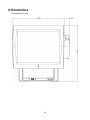
9. Dimensions
All dimensions in mm
45
46
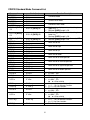
10.
Customer Display Command Settings
The Customer Display can be controlled through serial port COM7 after installation of the USB
VFD driver (see chapter 3.7)
The Customer Display default settings are:
• EPSON ESC/POS command set
• 9600 Baud, 8 bits, no parity, no flow control
Software Utilities
The following software utilities are provided for the customer display on the driver CD
Folder/File
File Description
<CD>:\Common\CustomerDisplay\Configuration
Configuration utility
<CD>:\Common\CustomerDisplay\Font_Editor
Font Editor utility
<CD>:\Common\CustomerDisplay\Firmware_Update Firmware update utility
A user manual for the utilities is available on the CD at the following location:
Folder/File
File Description
<CD>:\Common\CustomerDisplay\
User manual
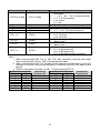
Software Status Setting Commands
When the system is powered on, it will read the EEPROM setting to set the Command Type,
Baud Rate, Parity, Data Length, Demo Mode setting and International Character Set. The
user can change the Software Status Setting Commands using the command sequences
described below.
47
Baud Rate Setting Command
STX 05 B n ETX
ASCII Format
Dec. Format
Hex. Format
Description
n
31h
30h
37h
36h
/Change the baud rate setting/
STX 05 B n ETX
[02] [05] [66] n [03]
[02h][05h][42h] n [03h]
n=30h, 31h, 36h or 37h
Change the display communication baud rate. The baud
rate setting can be selected from 4800 to 38400.
Baud rate
4800
9600
19200
38400
Parity Check Setting Command
STX 05 P n ETX
ASCII Format
Dec. Format
Hex. Format
Description
n
31h
33h
/Change the Parity check setting/
STX 05 P n ETX
[02] [05] [80] n [03]
[02h][05h][50h] n [03h]
n=31h, 33h
Change the display communication parity. Set 8 data bit and the
parity set for even or non-parity.
Parity
None
Even
Data Length Setting Command
STX 05 L n ETX
ASCII Format
Dec. Format
Hex. Format
Description
n
37h
38h
/Change the Data Length Setting/
STX 05 L n ETX
[02] [05] [76] n [03]
[02h][05h][4Ch] n [03h]
n=37h, 38h
Change the display communication data length. Set 8-bits or 7-bits
data length.
Parity
7 bits
8 bits
48
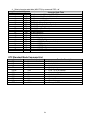
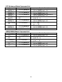
International Character Set Setting Command
Character Set Code Table
Note
(20h – 7Fh)
(80H-FFH)
30h
U.S.A.
CP-437 (USA, Standard Europe)
31h
FRANCE
32h
GERMANY
33h
U.K.
CP-858 (Multilingual + Euro Symbol)
34h
DENMARK I
35h
SWEDEN
36h
ITALY
37h
SPAIN
38h
JAPAN
Katakana
39h
NORWAY
CP-858 (Multilingual+ Euro Symbol)
3Ah
DENMARK II
3Bh
Slawie
3Ch
RUSSIA
3Dh
U.S.A.
CP-860 (Portuguese)
3Eh
U.K.
Greek
3Fh
U.S.A.
CP-852 (Hungary)
40h
U.S.A.
CP-862 (Hebrew)
41h
U.S.A.
CP-863 (Canadian-French)
42h
U.S.A.
CP-865 (Nordic)
43h
U.S.A.
CP-866 (Cyrillic)
44h
U.S.A.
Windows-1251 (Cyrillic)
45h
U.S.A.
Windows-1252 (West European Latin)
46h
U.S.A.
Windows-1255 (Hebrew)
47h
U.S.A.
Windows-1257 (Baltic)
48h
U.S.A.
Windows-1253 (Greek)
49h
U.S.A.
Windows-1250 (East European Latin)
4Ah ~ 4Eh Reserved
Reserved
4Fh
User Defined Character Set
n
49
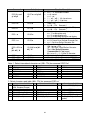
Select International Character Set Command
STX 05 T n ETX
ASCII Format
Dec. Format
Hex. Format
Description
/Select International Character Set Command/
STX 05 T n ETX
[02] [05] [84] n [03]
[02h][05h][54h] n [03h]
00h≦n≦1Fh
Select International Character Set
Select international character set (20H~7Fh) by command “STX 05 T n ETX”
International character set n
International character set n
International character set
n
00h
01h
02h
03h
04h
05h
U.S.A.
FRANCE
GERMANY
U.K.
DENMARK I
SWEDEN
06h
07h
08h
09h
0Ah
0Bh
ITALY
SPAIN
JAPAN
NORWAY
DENMARK II
SLAVONIC
0Ch
0Dh
0Eh
0Fh
1Fh
RUSSIA
Not used
Not used
Not used
User-Defined
Select Character Code Table Command
STX 05 U n ETX
ASCII Format
Dec. Format
Hex. Format
Description
/Select Character Code Table Command/
STX 05 U n ETX
[02] [05] [85] n [03]
[02h][05h][55h] n [03h]
00h≦n≦1Fh
Select Character Code Table
Select character code table (80H~FFh) by command “STX 05 U n ETX”
Character code table
Character code table
Character code table
n
n
n
00h CP-437
(USA, Standard Europe)
01h Katakana (for Japan)
07h
Russia
0Fh
Windows-1257 (Baltic)
08h
Greek
10h
02h CP-850 (Multilingual)
03h CP-860 (Portuguese)
09h CP-852 (Hungary)
0Ah CP-862 (Hebrew)
11h
12h
04h CP-863
(Canadian-French)
05h CP-865 (Nordic)
06h Slawie
0Bh CP-866 (Cyrillic)
13h
0Ch Windows-1251 (Cyrillic)
0Eh Windows-1255
(Hebrew)
1Fh
Windows-1252
(West European Latin)
Windows-1253 (Greek)
Windows-1250
(East European Latin)
CP-858 (Multilingual+
Euro Symbol)
User Defined
50
Command Type Setting Command
STX 05 C n ETX
ASCII Format
Dec. Format
Hex. Format
Description
n
30h
31h
32h
33h
Command Type
DSP800
ESC/POS
POS7300
ADM787
/Change the command type setting/
STX 05 C n ETX
[02] [05] [67] n [03]
[02h][05h][43h] n [03h]
30h≦ n≦37h
This command will change the command type and initialize the
display.
The display emulation mode is based on DSP800/ ESC/ ADM 787/
POS7300/ AEDEX/ UTC/ CD5220 mode
n
34h
35h
36h
37h
Command Type
AEDEX
UTC/P
UTC/S
CD5220
Run Demo message
STX 05 D 08 ETX
ASCII Format
Dec. Format
Hex. Format
Description
/Run demo message/
STX 05 D 08 ETX
[02][05][68][08][03]
[02h][05h][44h][08h][03h]
Run demo message for the display.
The demo message is available in POS7300, DSP800, EPSON
ESC/POS and CD5220 command modes.
Show Firmware Version
STX 05 V 01 ETX
ASCII Format
Dec. Format
Hex. Format
Description
/Show Firmware Version/
STX 05 V 01 ETX
[02][05][86][01][03]
[02h][05h][56h][01h][03h]
Show firmware version.
51
User Defined Character Command Set
Function
Command
Del 1 Character
Del All Characters
Set 1 Character
Read 1 Character
Read All
Characters
Description
Delete one user defined character data.
[02h][FDh][55h][00h][n]
[n] = 20h ~ FFh for displayable character codes
[02h][FDh][55h][01h][00h] Delete All User-Define Characters
Set one user defined character [n] = 20h ~ FFh for
[02h][FDh][55h][02h][n]
displayable character codes/[m1]~[m5] = Character
[m1][m2][m3][m4][m5]
data byte 1 ~ 5/Ref. table below
Read one user define character data
[02h][FDh][55h][03h][n]
[n] = 20h ~ FFh for displayable character codes
Read all user defined character data
[02h][FDh][55h][04h][00h]
(Character 20h ~ FFh)
Set User-Define Character 5x7 dot layer out
Bit assignment: bit 7 bit 6 bit 5 bit 4 bit 3 bit 2 bit 1 bit0
5x7 dot bit assignment: 1 means fill dot, 0 means empty dot.
m1 bit 7
m1 bit 2
m2 bit 5
m2 bit 0
m3 bit 3
m4 bit 6
m4 bit 1
m1 bit 6
m1 bit 1
m2 bit 4
m3 bit 7
m3 bit 2
m4 bit 5
m4 bit 0
m1 bit 5
m1 bit 0
m2 bit 3
m3 bit 6
m3 bit 1
m4 bit 4
m5 bit 7
m1 bit 4
m2 bit 7
m2 bit 2
m3 bit 5
m3 bit 0
m4 bit 3
m5 bit 6
m1 bit 3
m2 bit 6
m2 bit 1
m3 bit 4
m4 bit 7
m4 bit 2
m5 bit 5
52
Ex: character “0”
m1 byte data = 0x74
m2 byte data = 0x67
m3 byte data = 0x5C
m4 byte data = 0xC5
m5 byte data = 0xC0
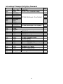
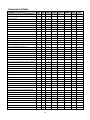
Command List Table
Command Set
Command
Move cursor right
POS
7300
O
CD
5220
O
EPSON
D101
O
Move cursor left
O
O
O
Move cursor up
O
O
O
Move cursor down
O
O
O
Move cursor to right-most position
O
O
O
Move cursor to left-most position
O
O
O
Move cursor to home position
O
O
O
Move cursor to bottom position
O
O
O
Move cursor to specified position
O
O
O
Clear display screen
O
O
O
Clear cursor line
O
O
O
Brightness adjustment
O
O
O
UTC/S
UTC/P
AEDEX
ADM
788
DSP
800
O
O
O
O
Blink display screen
O
O
O
O
Initialize display
O
O
O
O
Select character code table
O
O
O
Select international character set
O
O
O
Select/cancel reverse character
O
O
O
Overwrite mode
O
O
O
O
Vertical scroll mode
O
O
O
O
Horizontal scroll mode
O
O
O
Set/cancel the window range
O
O
O
Select peripheral device
O
O
O
Set starting/ending position of macro definition
O
Execute and quit macro
O
Execute self-test
O
Display time
O
O
O
Display time continuously
O
O
Display position
O
Cursor on/off
O
O
O
O
O
O
O
O
O
Change to UTC enhanced mode
O
O
Change to UTC standard mode
O
Write string to upper line
O
O
O
O
Upper line message continuous scroll
O
O
O
O
Bottom line message scroll continuously
O
Message vertical down scroll continuously
O
Message vertical upper scroll continuously
O
Carriage return
O
O
Line feed
O
O
Back space
O
O
Horizontal tab
O
Command type select
O
O
O
O
O
Upper line message scroll once pass
O
O
Change attention code
O
O
Two line display
O
O
53
Command Set
Command
Clear upper line and move cursor to upper
left-end position
POS
7300
CD
5220
EPSON
D101
UTC/S
UTC/P
AEDEX
ADM
788
DSP
800
O
Clear bottom line and move cursor to bottom
left-end position
O
Set period to upper line, last n position
O
Set line blinking, upper line
O
Clear line blinking, upper line
O
O
O
Clear field 1 and move cursor to field 1, first
position
Clear field 2 and move cursor to field 2,first
position
Clear display range from n position to m
position
move
cursor to data
n position
Save theand
current
displaying
to n layer for
O
O
O
O
demo
display
Turn annunciator
on/off
O
O
Specify period
O
O
Specify comma
O
O
Specify semicolon (period + comma)
O
O
Set/Cancel User-Define Character Set
O
Create User-define Character
O
Delete All User-Define Character
O
Store User-Define Character to EEPROM
O
Load User-Define Character from EEPROM
O
Delete 1 User-Define Character
O
O
54
Command Details
POS7300 Series Command List
Command
ESC F A [DATA]
CR
ESC F B [DATA]
CR
ESC F D [DATA]
CR
ESC F O [DATA]
CR
Code (hex)
1B 46 41 [DATA] 0D
1B 46 42 [DATA] 0D
1B 46 44 [DATA] 0D
1B 46 4F [DATA] 0D
ESC P x y
1B 50 x y
ESC _ n
1B 5F n
ESC DC1
ESC DC2
ESC DC3
ESC @
1B 11
1B 12
1B 13
1B 40
US MD1 n
1F 01 n
US MD2 n
1F 02 n
US DC1 n
1F 11 n
US DC2 n
1F 12 n
US # n x
1F 23 n x
US , n
1F 2C n
US . n
1F 2E n
US ; n
1F 3B n
US @
1F 40
US E n
1F 45 n
US T h m
1F 54 h m
US U
1F 55
US X n
1F 58 n
US r n
1F 72 n
NULL H
NULL K
NULL M
0 48
0 4B
0 4D
55
Function Description
Write string to upper line
Maximal [DATA] length is 40
Write string to lower line
Maximal [DATA] length is 40
Upper line message scroll continuously
Maximal [DATA] length is 40
Bottom line message scroll continuously
Maximal [DATA] length is 40
Move cursor to specified position
x = 1 ~ 14h, for columns location.
y = 1 ~ 2, for lines location.
Set cursor on/off
n = 00 ~ 01
Overwrite mode
Vertical scroll mode
Horizontal scroll mode
Initialize display
Message vertical upper scroll continuously
n = 01 ~ 0Ch
Message vertical down scroll continuously
n = 01 ~ 0Ch
Set line blinking
n = ’1’ ~ ’2’
n = ’1’ up line
n = ’2’ low line
Clear line blinking
n = ’1’ ~ ’2’
n = ’1’ up line
n = ’2’ low line
Turn annunciator on/off.
n = 0 for annunciator off
n = 1 for annunciator on
x = 1 ~ 14h, for columns location.
Specify comma
n = a displayable character code
Specify period
n = a displayable character code
Specify semicolon (period + comma)
n = a displayable character code
Execute self - test
Blink display screen
n = 00h ~ FFh
n = 0 for no blink
Display time
0 ≦ h ≦ 17h, for hours setting.
0 ≦ m ≦ 3Bh, for minutes setting.
Display time continuously
Brightness adjustment
n=1~ 4
Select/cancel reverse character.
n = 00,01
Move cursor up
Move cursor left
Move cursor right
Command
NULL P
NULL G
NULL O
BS
HT
LF
HOM
US B
CLR
CLR
CR
CAN
Code (hex)
0 50
0 47
0 4F
08
09
0A
0B
1F 42
0C
12
0D
18
DLE n
10 n
ESC W n s x1 y1
x2 y2
Function Description
Move cursor down
Move cursor to left-most position
Move cursor to right-most position
Back space
Horizontal tab
Line feed
Move cursor to home position
Move cursor to bottom position
Clear display screen
1B 57 n s x1 y1 x2 y2
ESC R n
1B 52 n
ESC t n
1B 74 n
ESC = n
1B 3D n
Carriage return
Clear cursor line, and clear string mode
Display position
n = 0 ~ 27h, for location.
Set or cancel the window range
n = 1 ~ 4, for window number
s = 0: cancel
s = 1: set
1 ≦ x1 ≦ x2 ≦ 14h, for columns
location.
1 ≦ y1 ≦ y2 ≦ 2, for lines location.
Select international character set
(20H~7Fh).
n = 00 ~ 1Fh. See note *1
Select character code table (80H~FFh).
n = 00 ~ 1Fh. See note *2
Select peripheral device, display or printer
n = 1~3
n = '1': enable printer only
n = '2': enable display only
n = '3': enable both of printer and
display
Note:
1. Select international character set (20H~7Fh) by command “ESC R n”
n
00h
01h
02h
03h
04h
International character set
U.S.A.
FRANCE
GERMANY
U.K.
DENMARK I
n
05h
06h
07h
08h
09h
International character set
SWEDEN
ITALY
SPAIN
JAPAN
NORWAY
n
International character set
0Ah DENMARK II
0Bh SLAVONIC
0Ch RUSSIA
1Fh User Defined
2. Select character code table (80H~FFh) by command “ESC t n”
n
Character code table
CP-437
00h
(USA, Standard Europe)
n
Character code table
07h Russia
0Fh Windows-1257 (Baltic)
01h Katakana (for Japan)
08h Greek
10h
02h CP-850 (Multilingual)
09h CP-852 (Hungary)
03h CP-860 (Portuguese)
0Ah CP-862 (Hebrew)
04h CP-863 (Canadian-French) 0Bh CP-866 (Cyrillic)
05h CP-865 (Nordic)
06h Slawie
0Ch Windows-1251 (Cyrillic)
0Eh Windows-1255 (Hebrew)
56
n
Character code table
Windows-1252
(West European Latin)
11h Windows-1253 (Greek)
Windows-1250
12h
(East European Latin)
CP-858 (Multilingual+ Euro
13h
Symbol)
1Fh User Defined
CD5220 Standard Mode Command List
Command
ESC DC1
US SOH
ESC DC2
US STX
ESC DC3
US ETX
1B 11
1F 01
1B 12
1F 02
1B 13
1F 03
Code (hex)
ESC Q A [DATA]
CR
1B 51 41 [DATA] 0D
ESC Q B [DATA]
CR
1B 51 42 [DATA] 0D
Function Description
Overwrite mode
Vertical scroll mode
Horizontal scroll mode
ESC Q D [DATA]
CR
ESD [ D
BS
ESC [ C
HT
ESC [ A
US LF
ESC [ B
LF
ESC [ H
HOM
ESC [ L
CR
ESC [ R
US CR
ESC [ K
US B
1B 5B 44
08
1B 5B 43
09
1B 5B 41
1F 0A
1B 5B 42
0A
1B 5B 48
0B
1B 5B 4C
0D
1B 5B 52
1F 0D
1B 5B 4B
1F 42
ESC # n
1B 23 n
US @
1F 40
US E n
1F 45 n
ESC I x y
1B 6C x y
US $ x y
1F 24 x y
ESC # n
1B 23 n
US E n
1F 45 n
ESC I x y
1B 6C x y
ESC @
1B 40
1B 51 44 [DATA] 0D
Set the string display mode, write string to
upper line. *1
Maximal [DATA] length is 20
Set the string display mode, write string to
lower line. *1
Maximal [DATA] length is 20
Upper line message scroll continuously. *1 *2
Maximal [DATA] length is 40
Move cursor left
Move cursor right
Move cursor up
Move cursor down
Move cursor to home position
Move cursor to left-most position
Move cursor to right-most position
Move cursor to bottom position
57
Command type select
n = 30h ~ 37h
Execute self test
Blink display screen
n = 00h ~ FFh
n = 0 for no blink
Move cursor to specified position
x = 1 ~ 14h, for columns location.
y = 1,2, for lines location.
Command type select
n = 30h ~ 37h
Blink display screen
n = 00h ~ FFh
n = 0 for no blink
Move cursor to specified position
x = 1 ~ 14h, for columns location.
y = 1,2, for lines location.
Initialize display
Command
Code (hex)
ESC W s x1 x2 y
1B 57 s x1 x2 y
CLR
CAN
ESC * n
US X n
0C
18
1B 2A n
1F 58 n
ESC _ n
1B 5F n
ESC f n
1B 66 n
ESC c n
1B 63 n
ESC = n
1B 3D n
Function Description
Set or cancel the window range at horizontal
scroll mode
1 ≦ x1 ≦ x2 ≦ 14h, for columns location.
y = 1~2, for lines location.
s = 0: cancel
s = 1: set
Clear display screen, and clear string mode
Clear cursor line, and clear string mode
Brightness adjustment
n = 1 ~ 4, n = 4 for highest brightness
Set cursor on/off
n = 1: cursor on
n = 0: cursor off
Select international Character
About n, refer. *3
Select character code table
About n, refer. *4
Select peripheral device, display or printer
n='1': enable printer only
n='2': enable display only
n='3': enable both of printer and display
Note:
1. While using command “ESC Q A” or “ESC Q B”, other commands cannot be used except
when using command “CLR” or “CAN” to change operating mode.
2. When using command “ESC Q D”, the upper line message will scroll continuously until a new
command is received, it will then clear the upper line and move the cursor to the upper left-end
position.
3. Select the international Character set (20h – 7Fh) by command “ESC f n”.
Parameter “n”
International
Parameter “n”
International
Character Set
Character Set
Character
Hex
Character
Hex
‘A’
41h
U.S.A.
‘N’
4Eh
Norway
‘G’
47h
Germany
‘W’
57h
Sweden
’I’
49h
Italy
‘D’
44h
Denmark I
‘J’
4Ah
Japan
‘E’
45h
Denmark II
‘U’
55h
U.K.
‘L’
4Ch
Slavonic
‘F’
46h
France
‘R’
52h
Russia
‘S’
53h
Spain
1Fh
User-Define
58
4. Select character code table (80H-FFH) by command “ESC c n”.
Parameter “n”
character Code Table
Character
Hex
‘A’
41h
Compliance with ASCII code (CP-437)
‘J’
4Ah Compliance with JIS code (Katakana)
‘L’
4Ch Compliance with Slawie code
‘R’
52h
Compliance with RUSSIA code
‘M’
4Dh CP-850 (Multilingual)
‘P’
50h
CP-858 (Multilingual+ Euro Symbol)
‘p’
70h
CP-860 (Portuguese)
‘F’
46h
CP-863 (Canadian-French)
‘N’
4Eh CP-865 (Nordic)
‘u’
75h
CP-852 (Hungary)
‘H’
48h
CP-862 (Hebrew)
‘C’
43h
CP-866 (Cyrillic)
‘G’
47h
Greek
‘c’
63h
Windows-1251 (Cyrillic)
‘W’
57h
Windows-1252 (West European Latin)
‘h’
68h
Windows-1255 (Hebrew)
‘B’
42h
Windows-1257 (Baltic)
‘g’
67h
Windows-1253 (Greek)
‘E’
45h
Windows-1250 (East European Latin)
1Fh
User Defined
UTC Standard Mode Command List
Command
BS
HT
LF
CR
08
09
0A
0D
Code (hex)
DLE n
10 n
DC1
DC2
DC3
DC4
US
ESC d
11
12
13
14
1F
1B 64
59
Function Description
Back space
Horizontal tab
Line feed
Carriage return
Display position
n = 0 ~ 27h, for location.
Over write display mode
Vertical scroll mode
Cursor on
Cursor off
Clear display
Change to UTC enhanced mode
UTC Enhanced Mode Command List
Command
ESC u A
[DATA] CR
ESC u B
[DATA] CR
ESC u D
[DATA] CR
ESC u E h h :
m m CR
ESC u F
[DATA] CR
ESC u H n m
CR
ESC u I
[DATA] CR
ESC RS CR
Code (hex)
1B 75 41 [DATA] 0D
1B 75 42 [DATA] 0D
1B 75 44 [DATA] 0D
1B 75 45 h h ':' m m
0D
1B 75 46 [DATA] 0D
1B 75 48 n m 0D
1B 75 49 [DATA] 0D
1B 0F 0D
Function Description
Upper line display
Maximal [DATA] length is 20
Bottom line display
Maximal [DATA] length is 20
Upper line message scroll continuously
Maximal [DATA] length is 40
Display time
h, m = '0' ~ '9'
Upper line message scroll Once pass
Maximal [DATA] length is 40
Change attention code
n = 1 ~ 20h
m = 1 ~ 20h
Two line display
Maximal [DATA] length is 40
Change to UTC standard mode
AEDEX/EMAX Mode Command List
Command
! # 4 [DATA]
CR
!#5hh:mm
CR
21 23 35 h h ':' m m
0D
! # 8 n m CR
21 23 38 n m 0D
! # 9 [DATA]
CR
! # 6 [DATA]
CR
Code (hex)
21 23 34 [DATA] 0D
21 23 39 [DATA] 0D
21 23 36 [DATA] 0D
60
Function Description
Upper line message scroll
Maximal [DATA] length is 40
Display time
h, m = '0' ~ '9'
Change attention code
n, m = 1 ~ 20
Two line display
Maximal [DATA] length is 40
Upper line message scroll once pass
Maximal [DATA] length is 40
ADM787/788 mode command list
Command
CLR
CR
0C
0D
Code (hex)
SLE1
0E
SLE2
0F
DC0 n
10 n
DC1 n
11 n
DC2 n
12 n
SF1
1E
SF2
1F
61
Function Description
Clear display
Carriage return
Clear upper line and move cursor to upper
left-end position
Clear bottom line and move, Cursor to bottom
left-end position
Set period to upper line last n position
n = 31H ~ 37H
Set line blinking, upper line
n = '1' ~ '2'
n = '1': up line
n = '2': low line
Clear line blinking, upper line
n = '1' ~ '2'
n = '1': up line
n = '2': low line
Clear field 1 and move cursor to field 1, first
position
Clear field 2 and move cursor to field 2, first
position
DSP800 Mode Command List
Command
EOT SOH I n
ETB
EOT SOH P n
ETB
EOT SOH C n
m
ETB
Code (hex)
04 01 49 n 17
04 01 50 n 17
04 01 43 n m 17
EOT SOH S n
ETB
04 01 53 n 17
EOT SOH D n
m ETB
04 01 44 n m 17
EOT SOH A n
ETB
EOT SOH F n
ETB
EOT SOH # n
ETB
EOT SOH %
ETB
EOT SOH @
ETB
04 01 41 n 17
n =31h-34h
04 01 46 n 17
00h n FFh
04 01 23 n 17
n =30~37h
EOT SOH & n
[m1~m5] ETB
04 01 26 n [m1~m5]
17
EOT SOH ? n
ETB
04 01 3F n 17
EOT SOH = n
ETB
04 01 3D n 17
Function Description
Select international character set
n = 00 ~ 1Fh or 30 ~ 4Fh See note *1
Move cursor to specified position
n = 31h ~ 58h
Clear display range from n position to m
position and move cursor to n position
31h ≦ n ≦ m ≦ 58h
Save current view message to n layer for
demo view data
n = 31h ~ 35h
Display the saved demo message
n = 31h ~ 4Fh
m = 31h ~ 33h
Brightness adjustment
Blink display Screen
n = 00h ~ FFh, n = 0 for no blink
Command type select
04 01 25 17
Initialize display
04 01 40 17
Execute self-test
Note:
Set One User-Define Character
n = 20h ~ FFh for displayable character code
[m1 ~ m5] Byte1~Byte5 Define Character
Delete One User-Define Character
n = 20h ~ FFh for displayable character code
Select peripheral device, display or printer
n = '1': enable printer only
n = '2': enable display only
n = '3': enable both of printer and display
1. Select international character set (20H~7Fh) by command “EOT SOH I n ETB”
International character
International character
n
n
n International character set
set
set
00h U.S.A.
05h SWEDEN
0Ah DENMARK II
01h FRANCE
06h ITALY
0Bh SLAVONIC
02h GERMANY
07h SPAIN
0Ch RUSSIA
03h U.K.
08h JAPAN
04h DENMARK I
09h NORWAY
1Fh User-Define
30h U.S.A.
35h SWEDEN
3Ah DENMARK II
31h FRANCE
36h ITALY
3Bh SLAVONIC
32h GERMANY
37h SPAIN
3Ch RUSSIA
33h U.K.
38h JAPAN
34h DENMARK I
39h NORWAY
4Fh User-Define
62
EPSON ESC/POS Command List
Command
Code (hex)
US r n
1F 72 n
US MD1
US MD2
US MD3
CAN
1F 01
1F 02
1F 03
18
ESC # n
1B 23 n
US # n x
1F 23 n x
US C n
1F 43 n
BS
HT
US LF
LF
US CR
CR
HOM
US B
08
09
1F 0A
0A
1F 0D
0D
0B
1F 42
US $ x y
1F 24 x y
CLR
0C
US E n
1F 45 n
ESC @
1B 40
US , n
1F 2C n
US . n
1F 2E n
US ; n
1F 3B n
US :
1F 3A
US ^ n m
1F 5E n m
US @
1F 40
US T h m
1F 54 h m
US U
1F 55
US X n
1F 58 n
63
Function Description
Select/cancel reverse character.
n = 00,01
Specify overwrite mode.
Specify vertical scroll mode.
Specify horizontal scroll mode.
Clear cursor line
Command type select
n = 30h ~ 37h
Turn annunciator on/off.
n = 0 for annunciator off
n = 1 for annunciator on
x = 1 ~ 14h, for columns location.
Set cursor on/off
n = 00, 01
Move cursor left
Move cursor right
Move cursor up
Move cursor down
Move cursor to right-most position
Move cursor to left-most position
Move cursor to home position
Move cursor to bottom position
Move cursor to specified position
x = 1 ~ 14h, for columns location.
y = 1 ~ 2, for lines location.
Clear display screen
Blink display screen
n = 00h ~ FFh
n = 0 for no blink
Initialize display
Specify comma
n = a displayable character code
Specify period
n = a displayable character code
Specify semicolon (period + comma)
n = a displayable character code
Set starting/ending position of macro
definition.
Ex.: 1F 3A … (macro string) … 1F 3A
Execute and quit macro. It’s an interval of n
between the two words. It’s an interval of m
between the two strings.
00 (n, m) FFh
n = Word time
m = show string time
Execute self - test
Display time
0 ≦ h ≦ 17h, for hours setting.
0 ≦ m ≦ 3Bh, for minutes setting.
Display time continuously
Brightness adjustment
n=1~4
Command
ESC W n s x1
y1 x2 y2
Code (hex)
1B 57 n s x1 y1 x2
y2
ESC R n
1B 52 n
ESC t n
1B 74 n
ESC = n
1B 3D n
ESC % n
1B 25 n
ESC & SOH n
m
[b1~b5] * K
1B 26 01 n m [b1 ~
b5] * K
ESC ?
ESC s SOH
ESC d SOH
1B 3F
1B 73 01
1B 64 01
Function Description
Set or cancel the window range
n = 1 ~ 4, for window number
s = 0: cancel
s = 1: set
1 ≦ x1 ≦ x2 ≦ 14h, for columns
1 ≦ y1 ≦ y2 ≦ 2, for lines .
Select international character set
(20H~7Fh).
n = 00 ~ 1Fh. See note *1
Select character code table (80H~FFh).
n = 00 ~ 1Fh. See note *2
Select peripheral device, display or printer
n = '1': enable printer only
n = '2': enable display only
n = '3': enable both of printer and display
Set/Cancel User-Define Character Set
n = 0: Cancel User-Defined Character Set
n = 1: Set User-Define Character Set
Create User-define Character
20h ≤ n ≤ m ≤ FFh
[b1 ~ b5] Byte1~Byte5 Define Character
(Ref. User-Define Character
Command-Set 5x7 dot layout )
K = (m-n+1) → 1 ~ 5, Max. 5 character.
Delete User-Define Character
Store User-Define Character in EEPROM
Load User-Define Character from EEPROM
Note: 1. Select international character set (20H~7Fh) for command “ESC R n”
n
0h
1h
2h
3h
4h
5h
international character set
U.S.A.
FRANCE
GERMANY
U.K.
DENMARK I
SWEDEN
n
6h
7h
8h
9h
Ah
Bh
international character set
ITALY
SPAIN
JAPAN
NORWAY
DENMARK II
SLAVONIC
n
Ch
Dh
Eh
Fh
international character set
RUSSIA
Not used
Not used
Not used
2. Select character code table (80H~FFh) for command “ESC t n”
n
character code table
n
character code table
0h CP-437
6h Slawie
(USA, Standard Europe)
1h Katakana (for Japan)
7h Russia
2h CP-850 (Multilingual)
8h Greek
3h CP-860 (Portuguese)
9h CP-852 (Hungary)
4h CP-863 (Canadian-French) Ah CP-862 (Hebrew)
5h CP-865 (Nordic)
Bh CP-866 (Cyrillic)
64
n
character code table
Ch Windows-1251 (Cyrillic)
Eh
Fh
10h
11h
13h
Windows-1255 (Hebrew)
Windows-1257 (Baltic)
Windows-1252
Windows-1253 (Greek)
CP-858 (Multilingual+ Euro
Symbol)
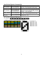
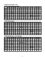
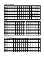
Character Set
Character Codes 20H – 7FH
International Character Sets
Character Code Number
Hex
23
24
40
5B
5C
5D
5E
60
7B
7C
7D
7E
Dec
35
36
64
91
92
93
94
96
123
124
125
126
U.S.A
#
$
@
[
\
]
^
`
{
¦
}
~
France
#
$
à
°
ç
§
^
`
é
ù
è
¨
Germany
#
$
§
Ä
Ö
Ü
^
`
ä
ö
ü
β
U.K
£
$
@
[
\
]
^
`
{
¦
}
~
Denmark I
#
$
@
Æ
Ø
Å
^
`
æ
ø
å
~
Sweden
#
¤
É
Ä
Ö
Å
Ü
é
ä
ö
å
ü
Italy
#
$
@
°
\
é
^
ù
à
ò
è
ì
Spain
Pt
$
@
¡
Ñ
¿
^
`
¨
ñ
}
~
Japan
#
$
@
[
¥
]
^
`
{
¦
}
~
Norway
#
¤
É
Æ
Ø
Å
Ü
é
æ
ø
å
ü
Denmark II
#
$
É
Æ
Ø
Å
Ü
é
æ
ø
å
ü
Slavonic
#
$
@
[
\
]
^
`
{
¦
}
~
Russia
#
$
@
[
\
]
^
`
{
¦
}
~
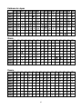
Country
USA, Standard Character Sets
00h 01h 02h 03h 04h 05h 06h 07h 08h 09h 0Ah 0Bh 0Ch 0Dh 0Eh 0Fh
20h
!
“
#
$
%
&
‘
(
)
*
+
,
-
.
/
30h
0
1
2
3
4
5
6
7
8
9
:
;
<
=
>
?
40h
@
A
B
C
D
E
F
G
H
I
J
K
L
M
N
O
50h
P
Q
R
S
T
U
V
W
X
Y
Z
[
\
]
^
_
60h
`
a
b
c
d
e
f
g
h
i
j
k
l
m
n
o
70h
p
q
r
s
t
u
v
w
x
y
Z
{
¦
}
~
65
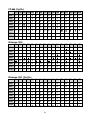
Character Codes 80H – FFH
CP-437 (USA, Standard Europe)
00h 01h 02h 03h 04h 05h 06h 07h 08h 09h 0Ah 0Bh 0Ch 0Dh 0Eh 0Fh
80h
Ç
ü
é
â
ä
à
å
ç
ê
ë
è
ï
î
ì
Ä
Å
90h
É
æ
Æ
ô
ö
ò
û
ù
ÿ
Ö
Ü
¢
£
¥
Pt
ƒ
A0h
á
í
ó
ú
ñ
Ñ
ª
º
¿
⌐
¬
½
¼
¡
«
»
B0h
░
▒
▓
│
┤
╡
╢
╖
╕
╣
║
╗
╝
╜
╛
┐
C0h
└
┴
┬
├
─
┼
╞
╟
╚
╔
╩
╦
╠
═
╬
╧
D0h
╨
╤
╥
╙
╘
╒
╓
╫
╪
┘
┌
█
▄
▌
▐
▀
E0h
α
ß
Γ
π
Σ
σ
µ
τ
Φ
θ
Ω
δ
∞
ø
ε
∩
F0h
≡
±
≥
≤
⌠
⌡
÷
≈
°
•
·
√
n
²
■
CP-850 (Multilingual)
00h 01h 02h 03h 04h 05h 06h 07h 08h 09h 0Ah 0Bh 0Ch 0Dh 0Eh 0Fh
80h
Ç
ü
é
â
ä
à
å
ç
ê
ë
è
ï
î
ì
Ä
Å
90h
É
æ
Æ
ô
ö
ò
û
ù
ÿ
ö
Ü
ø
£
Ø
×
ƒ
A0h
á
í
ó
ú
ñ
Ñ
a
o
¿
®
¬
½
¼
¡
«
»
B0h
░
▒
▓
│
┤
Á
Â
À
©
╣
║
╗
╝
¢
¥
┐
C0h
└
┴
┬
├
─
┼
ã
Ã
╚
╔
╩
╦
╠
═
╬
¤
D0h
ð
Đ
Ê
Ë
È
l
Í
Î
Ï
┘
「
█
▄
¦
Ì
▀
E0h
ó
ß
ô
ò
õ
Õ
µ
þ
Þ
Ú
Û
Ù
ý
Ý
¯
´
F0h
¯
±
=
¾
¶
§
÷
,
˚
¨
˙
1
3
2
■
CP-858 (Multilingual + Euro Symbol)
00h 01h 02h 03h 04h 05h 06h 07h 08h 09h 0Ah 0Bh 0Ch 0Dh 0Eh 0Fh
80h
Ç
ü
é
â
ä
à
å
ç
ê
ë
è
ï
î
ì
Ä
Å
90h
É
æ
Æ
ô
ö
ò
û
ù
ÿ
ö
Ü
ø
£
Ø
×
ƒ
A0h
á
í
ó
ú
ñ
Ñ
a
o
¿
®
¬
½
¼
¡
«
»
B0h
░
▒
▓
│
┤
Á
Â
À
©
╣
║
╗
╝
¢
¥
┐
C0h
└
┴
┬
├
─
┼
ã
Ã
╚
╔
╩
╦
╠
═
╬
¤
D0h
ð
Đ
Ê
Ë
È
€
Í
Î
Ï
┘
「
█
▄
¦
Ì
▀
E0h
ó
ß
ô
ò
õ
Õ
µ
þ
Þ
Ú
Û
Ù
ý
Ý
¯
´
F0h
¯
±
=
¾
¶
§
÷
,
˚
¨
˙
1
3
2
■
66
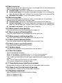
Katakana for Japan
00h 01h 02h 03h 04h 05h 06h 07h 08h 09h 0Ah 0Bh 0Ch 0Dh 0Eh 0Fh
80h
α
β
γ
⊿
є
90h
£
§
IE
IR
∫
η
x
。
「
」
、
‧
A0h
θ
λ
µ
π
ρ
σ
τ
Ф
Ω
∑
Ā
-1
²
³
x
½
1
√
±
■
"
∘
∴
∵
⊕
Θ
/
B0h
C0h
D0h
E0h
F0h
≤
≥
≠
≒
║
│
⊥
”
“
«
∞
α
~
~
≣
〒
»
Slawie
00h 01h 02h 03h 04h 05h 06h 07h 08h 09h 0Ah 0Bh 0Ch 0Dh 0Eh 0Fh
80h
Ç
ü
é
â
ä
ů
ć
ç
Į
ë
õ
õ
î
ź
ä
ć
90h
é
Ĺ
í
ô
ö
Ľ
ĭ
ś
ś
Ö
Ü
ť
ť
ł
х
č
A0h
á
í
ó
ú
ą
ą
ž
ž
ę
ę
ź
č
ş
«
»
B0h
░
▒
▓
│
┤
á
â
ĕ
ş
ŧ
ŧ
─
┼
ă
ă
C0h
¤
═
D0h
đ
đ
ď
ë
ď
ň
í
î
ě
E0h
ó
β
ô
ń
ń
ň
š
š
ŕ
ú
F0h
–
r
s
ˇ
˘
§
÷
د
˚
¨
█
▄
ţ
ů
▀
ŕ
ũ
ý
ý
ţ
q
˙
ũ
ř
ř
■
Russia
00h 01h 02h 03h 04h 05h 06h 07h 08h 09h 0Ah 0Bh 0Ch 0Dh 0Eh 0Fh
80h
А
Б
В
Г
Д
Е
Ж
З
и
Й
К
Л
М
Н
О
П
90h
Р
С
Т
У
Ф
Х
Ц
Ч
Ш
Щ
Ъ
Ы
Ь
Э
Ю
Я
A0h
а
б
в
г
д
е
ж
з
и
й
к
л
м
н
о
п
E0h
р
с
т
у
ф
х
ц
ч
ш
щ
ъ
ы
ь
Э
ю
я
F0h
∂
Ғ
Қ
Ң
θ
Ұ
Y
Һ
∂
ғ
қ
ң
θ
ұ
Y
B0h
C0h
D0h
67
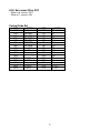
CP-860 (Portuguese)
00h 01h 02h 03h 04h 05h 06h 07h 08h 09h 0Ah 0Bh 0Ch 0Dh 0Eh 0Fh
80h
Ç
ü
é
â
ã
à
Á
ç
ê
Ê
è
Í
Ô
ì
Ã
Â
90h
É
À
È
ô
õ
ò
Ú
ù
Ì
Õ
Ü
¢
£
Ù
Pt
Ó
A0h
á
í
ó
ú
ñ
Ñ
a
¿
®
¬
½
¼
¡
«
»
B0h
░
▒
▓
│
┤
╡
╢
o
╖
╕
╣
║
╗
╝
╜
╛
┐
C0h
└
┴
┬
├
─
┼
╞
╟
╚
╔
╩
╦
╠
═
╬
╧
D0h
╨
╤
╥
╙
╘
╒
╓
╫
╪
┘
└
█
▄
▌
▐
▀
E0h
α
β
Γ
π
Σ
σ
µ
τ
Ф
θ
Ω
δ
∞
ø
є
∩
F0h
≡
±
≥
≤
⌠
⌡
÷
≈
°
•
·
√
n
²
■
06h
07h 08h 09h 0Ah 0Bh 0Ch 0Dh 0Eh 0Fh
Greek
00h 01h 02h 03h 04h 05h
80h
Α
Β
Γ
∆
Ε
Ζ
Η
Θ
Ι
Κ
Λ
Μ
Ν
Ξ
Ο
Π
90h
Ρ
Σ
Τ
Y
Φ
Х
Ψ
Ω
α
β
γ
δ
ε
ζ
η
θ
A0h
ι
κ
λ
µ
ν
ξ
ο
π
ρ
σ
s
τ
υ
φ
χ
ψ
B0h
C0h
D0h
E0h
ω
£
F0h
-
CP-852 (Hungary)
00h 01h 02h 03h 04h 05h 06h 07h 08h 09h 0Ah 0Bh 0Ch 0Dh 0Eh 0Fh
80h
Ç
ű
é
â
ä
ů
ć
ç
ł
ë
Ő
ő
î
Ź
Ä
Ć
90h
É
Ĺ
ĺ
ô
ö
Ľ
ľ
Ś
ś
Ö
Ü
Ť
ť
Ł
x
Č
A0h
á
í
ó
ú
Ą
ą
Ž
ž
Ę
ę
¬
ź
Č
ş
«
»
B0h
░
▒
▓
│
┤
Á
Â
Ĕ
Ş
╣
║
╗
╝
ż
ż
┐
C0h
└
┴
┬
├
─
┼
Ä
ǎ
╚
╔
╩
╦
╠
═
╬
¤
D0h
đ
Đ
Ď
Ë
ď
Ň
Í
Î
ě
┘
г
█
▄
Ţ
Ů
▀
E0h
Ó
ß
Ô
Ń
ń
ň
Š
š
Ŕ
Ú
ŕ
Ű
ý
Ý
ţ
´
F0h
–
r
s
ˇ
˘
§
÷
د
˚
¨
˙
ũ
Ř
ř
■
68
CP-862 (Hebrew)
00h 01h 02h 03h 04h 05h 06h 07h 08h 09h 0Ah 0Bh 0Ch 0Dh 0Eh 0Fh
80h
א
ב
ג
ד
ה
ו
ז
ח
ט
י
ך
כ
ל
ם
מ
ן
90h
נ
ס
ע
ף
פ
ץ
צ
ק
ר
ש
ת
¢
£
¥
₧
ƒ
A0h
á
í
ó
ú
ñ
Ñ
ª
º
¿
⌐
¬
½
¼
¡
«
»
B0h
░
▒
▓
│
┤
╡
╢
╖
╕
╣
║
╗
╝
╜
╛
┐
C0h
└
┴
┬
├
─
┼
╞
╟
╚
╔
╩
╦
╠
═
╬
╧
D0h
╨
╤
╥
╙
╘
╒
╓
╫
╪
┘
┌
█
▄
▌
▐
▀
E0h
α
ß
Γ
π
Σ
σ
µ
τ
Φ
Θ
Ω
δ
∞
φ
ε
∩
F0h
≡
±
≥
≤
⌠
⌡
÷
≈
°
·
·
√
ⁿ
²
■
CP-863 (Canadian- French)
00h 01h 02h 03h 04h 05h 06h 07h 08h 09h 0Ah 0Bh 0Ch 0Dh 0Eh 0Fh
80h
Ç
ü
é
â
Â
à
¶
ç
ê
ë
è
ï
î
=
Ä
§
90h
É
È
Ê
ô
Ë
Ï
û
ù
¤
Ô
Ü
¢
£
Ù
Û
ƒ
A0h
¦
í
‘
ó
ú
¨
,
¯
Î
⌐
¬
½
¼
¾
«
»
B0h
░
▒
▓
│
┤
╡
╢
╖
╕
╣
║
╗
╝
╜
╛
┐
C0h
└
┴
┬
├
─
┼
╞
╟
╚
╔
╩
╦
╠
═
╬
╧
D0h
╨
╤
╥
╙
╘
╒
╓
╫
╪
┘
┌
█
▄
▌
▐
▀
E0h
α
ß
Γ
π
Σ
σ
µ
τ
Φ
Θ
Ω
δ
∞
φ
ε
∩
F0h
≡
±
≥
≤
⌠
⌡
÷
≈
°
·
·
√
ⁿ
²
■
CP-865 (Nordic)
00h 01h 02h 03h 04h 05h 06h 07h 08h 09h 0Ah 0Bh 0Ch 0Dh 0Eh 0Fh
80h
Ç
ü
é
â
ä
à
å
ç
ê
ë
è
ï
î
ì
Ä
Å
90h
É
æ
Æ
ô
ö
ò
Ö
Ü
ø
£
Ø
Pt
ƒ
á
í
ó
ú
ñ
Ñ
ù
o
ÿ
A0h
û
a
¿
®
¬
½
¼
¡
«
¤
B0h
░
▒
▓
│
┤
╡
╢
╖
╕
╣
║
╗
╝
╜
╛
┐
C0h
└
┴
┬
├
─
┼
╞
╟
╚
╔
╩
╦
╠
═
╬
╧
D0h
╨
╤
╥
╙
╘
╒
╓
╫
╪
┘
┌
█
▄
▌
▐
▀
E0h
α
ß
Γ
π
Σ
σ
µ
τ
Φ
θ
Ω
δ
∞
ø
ε
∩
√
n
²
■
F0h
≡
±
≥
≤
⌠
⌡
÷
≈
69
°
•
·
CP-866 (Cyrillic)
00h 01h 02h 03h 04h 05h 06h 07h 08h 09h 0Ah 0Bh 0Ch 0Dh 0Eh 0Fh
80h
А
Б
В
Г
Д
Е
Ж
З
И
Й
К
Л
М
Н
О
П
90h
Р
С
Т
У
Ф
Х
Ц
Ч
Ш
Щ
Ъ
Ы
Ь
Э
Ю
Я
A0h
а
б
в
г
д
е
ж
з
и
й
к
л
м
н
о
п
B0h
░
▒
▓
│
┤
╡
╢
╖
╕
╣
║
╗
╝
╜
╛
┐
C0h
└
┴
┬
├
─
┼
╞
╟
╚
╔
╩
╦
╠
═
╬
╧
D0h
╨
╤
╥
╙
╘
╒
╓
╫
╪
┘
┌
█
▄
▌
▐
▀
E0h
р
с
т
у
ф
х
ц
ч
ш
щ
ъ
ы
ь
э
ю
я
F0h
Ё
ё
Є
є
Ї
ї
Ў
ў
°
·
·
√
№
¤
■
Windows-1250
00h 01h 02h 03h 04h 05h 06h 07h 08h 09h 0Ah 0Bh 0Ch 0Dh 0Eh 0Fh
80h
‚
€
„
…
†
‡
‰
Š
‹
Ś
Ť
Ž
Ź
™
š
›
ś
ť
ž
ź
®
Ż
90h
‘
’
“
”
•
–
—
A0h
ˇ
˘
Ł
¤
Ą
¦
§
¨
©
Ş
«
¬
B0h
°
±
˛
ł
´
µ
¶
·
¸
ą
ş
»
Ľ
˝
ľ
ż
C0h
Ŕ
Á
Â
Ă
Ä
Ĺ
Ć
Ç
Č
É
Ę
Ë
Ě
Í
Î
Ď
D0h
Ð
Ń
Ň
Ó
Ô
Ő
Ö
×
Ř
Ů
Ú
Ű
Ü
Ý
Ţ
ß
E0h
ŕ
á
â
ă
ä
ĺ
ć
ç
č
é
ę
ë
ě
í
î
ď
F0h
đ
ń
ň
ó
ô
ő
ö
÷
ř
ů
ú
ű
ü
ý
ţ
˙
Windows-1251 (Cyrillic)
00h 01h 02h 03h 04h 05h 06h 07h 08h 09h 0Ah 0Bh 0Ch 0Dh 0Eh 0Fh
80h
Ђ
Ѓ
‚
ѓ
„
…
†
‡
90h
ђ
‘
’
“
”
•
–
—
Ў
ў
Ј
¤
Ґ
¦
§
Ё
A0h
€
‰
Љ
‹
Њ
Ќ
Ћ
Џ
™
љ
›
њ
ќ
ћ
џ
©
Є
«
¬
®
Ї
є
»
ј
Ѕ
ѕ
ї
B0h
°
±
І
і
ґ
µ
¶
·
ё
C0h
А
Б
В
Г
Д
Е
Ж
З
И
Й
К
Л
М
Н
О
П
D0h
Р
С
Т
У
Ф
Х
Ц
Ч
Ш
Щ
Ъ
Ы
Ь
Э
Ю
Я
E0h
а
б
в
г
д
е
ж
з
и
й
к
л
м
н
о
п
F0h
р
с
т
у
ф
х
ц
ч
ш
щ
ъ
ы
ь
э
ю
я
70
№
Windows-1252
00h 01h 02h 03h 04h 05h 06h 07h 08h 09h 0Ah 0Bh 0Ch 0Dh 0Eh 0Fh
80h
€
‚
ƒ
„
…
†
‡
ˆ
‰
Š
‹
Œ
Ž
90h
‘
’
“
”
•
–
—
˜
™
š
›
œ
ž
Ÿ
A0h
¡
¢
£
¤
¥
¦
§
¨
©
ª
«
¬
®
¯
B0h
°
±
²
³
´
µ
¶
·
¸
¹
º
»
¼
½
¾
¿
C0h
À
Á
Â
Ã
Ä
Å
Æ
Ç
È
É
Ê
Ë
Ì
Í
Î
Ï
D0h
Ð
Ñ
Ò
Ó
Ô
Õ
Ö
×
Ø
Ù
Ú
Û
Ü
Ý
Þ
ß
E0h
à
á
â
ã
ä
å
æ
ç
è
é
ê
ë
ì
í
î
ï
F0h
ð
ñ
ò
ó
ô
õ
ö
÷
ø
ù
ú
û
ü
ý
þ
ÿ
Windows-1253 (Greek)
00h 01h 02h 03h 04h 05h 06h 07h 08h 09h 0Ah 0Bh 0Ch 0Dh 0Eh 0Fh
80h
€
‚
ƒ
„
…
†
‡
‰
‹
™
›
«
¬
–
®
¯
90h
‘
’
“
”
•
–
—
A0h
΅
Ά
£
¤
¥
¦
§
¨
©
B0h
±
²
³
´
µ
¶
·
Έ
Ή
Ί
»
Ό
½
Ύ
Ώ
Β
Γ
∆
Ε
Ζ
Η
Θ
Ι
Κ
Λ
Μ
Ν
Ξ
Ο
Σ
Τ
Υ
Φ
Χ
Ψ
Ω
Ϊ
Ϋ
ά
έ
ή
ί
ο
C0h
ΐ
Α
D0h
Π
Ρ
E0h
ΰ
α
β
γ
δ
ε
ζ
η
θ
ι
κ
Λ
µ
ν
ξ
F0h
π
ρ
ς
σ
τ
υ
φ
χ
ψ
ω
ϊ
ϋ
ό
ύ
ώ
Windows-1255 (Hebrew)
00h 01h 02h 03h 04h 05h 06h 07h 08h 09h 0Ah 0Bh 0Ch 0Dh 0Eh 0Fh
80h
€
‚
ƒ
„
…
†
‡
ˆ
‰
‹
›
90h
‘
’
“
”
•
–
—
˜
™
A0h
¡
¢
£
₪
¥
¦
§
¨
©
×
«
¬
–
®
¯
÷
»
¼
½
¾
¿
ֻ
ּ
s
=
ֿ
B0h
°
±
²
³
´
µ
¶
·
¸
¹
C0h
ְ
ֱ
ֲ
ֳ
ִ
ֵ
ֶ
ַ
ָ
ֹ
D0h
?
@
A
B
C
D
E
F
G
,
:
;
.
!
?
E0h
א
ב
ג
ד
ה
ו
ז
ח
ט
י
ך
כ
ל
ם
מ
F0h
נ
ס
ע
ף
פ
ץ
צ
ק
ר
ש
ת
71
ן
Windows-1257 (Baltic)
00h 01h 02h 03h 04h 05h 06h 07h 08h 09h 0Ah 0Bh 0Ch 0Dh 0Eh 0Fh
80h
‚
€
‘
90h
A0h
„
…
†
‡
‰
‹
¨
ˇ
•
–
—
™
›
¯
˛
¦
§
Ø
©
Ŗ
«
¬
–
®
Æ
’
“
”
¢
£
¤
¸
B0h
°
±
²
³
´
µ
¶
·
ø
¹
ŗ
»
¼
½
¾
æ
C0h
Ą
Į
Ā
Ć
Ä
Å
Ę
Ē
Č
É
Ź
Ė
Ģ
Ķ
Ī
Ļ
D0h
Š
Ń
Ņ
Ó
Ō
Õ
Ö
×
Ų
Ł
Ś
Ū
Ü
Ż
Ž
ß
E0h
ą
į
ā
ć
ä
å
ę
ē
č
é
ź
ė
ģ
ķ
ī
ļ
F0h
š
ń
ņ
ó
ō
õ
ö
÷
ų
ł
Ś
ū
ü
ż
ž
˙
72
Command Details
A.1. Overwrite mode
In this mode, the cursor will move towards the right and begin from the upper left position.
When the cursor has reached the end of the upper line, the cursor will move down to the
bottom left position to continue. When the cursor has reached the end of the bottom line, it
will move to up the upper left position and overwrite the previous characters.
A.2. Vertical scroll mode
In this mode, the cursor will move towards the right. The cursor will begin from the upper left
position until it has reached the end of the upper line. The cursor will then move down to the
bottom left position to continue until it has reached the end of the bottom line.
A.3. Horizontal scroll mode
In this mode, the extent of the cursor activity is bound by a predefined range, limited to the
upper line. (Please refer to Set or cancel window command), where the default window is
the whole upper line. The cursor will begin from the left-end of the range and move
rightward until it reached the end of the range, to continue, the characters that comes
thereafter will start pushing the previous characters leftward from the right-end, scrolling the
characters to the left.
A.4. Set the string display mode and write string to display
Set the string display mode, write to upper or lower line d1 d2 d3 … dn {1≦n≦20}. ‘A’
stands for the upper line, ‘B’ stands for the lower line. The string display mode will be
cancelled and the display will return to the previous mode after receiving CLR or CAN.
A.5. Upper line message continuous scroll
The message (previously defined) will scroll continuously in the horizontal direction until a
new command is received.
A.6. Move cursor left
When the current cursor is at the left-end position, this command operates differently
depending on the display mode.
Overwrite mode: When the cursor reached the left-end of the lower line, it will continue
to the right-end of the upper line, overwrite previous characters. When it reached the
left end of the upper line, it will continue to the right-end of the lower line.
Vertical scroll mode: When the cursor reached the left-end of the lower line, the lower
line will scroll up and replace the previous upper line, the lower line will be cleared and
the cursor will continue to the right end of the lower line.
Horizontal scroll mode: The cursor will remain stationary.
A.7. Move cursor right
Move the cursor to the right. When the cursor has reached the right-end, this command
operates differently depending on the display mode.
Overwrite mode: When the cursor has reached the right-end of the lower line, it will
continue to the left-end of the upper line and overwrite previous characters. When it has
reached the right-end of the upper line, it will continue to the right-end of the lower line.
Vertical scroll mode: When the cursor has reached the right-end of the lower line, the
lower line will scroll up to replace the upper line, the lower line is cleared and ready to
continue characters thereafter.
Horizontal scroll mode: The cursor will remain stationary.
73
A.8. Move cursor up
Move the cursor up one line. When the cursor is on the upper line, this command operates
differently depending on the display mode.
Overwrite mode: The cursor is moved to the same column the lower line.
Vertical scroll mode: The characters displayed on the upper line is scrolled to the
lower line, and the upper line is cleared. The cursor will remain at the same position.
Horizontal scroll mode: The cursor will remain stationary.
A.9. Move cursor down
Move the cursor down one line. When the cursor is on the lower line, this command
operates differently depending on the display mode.
Overwrite mode: The cursor is moved to the same column on the upper line.
Vertical scroll mode: The characters displayed on the lower line are scrolled to the
upper line, and the lower line is cleared. The cursor will remain at the same position.
Horizontal scroll mode: The cursor will remain stationary.
A.10. Move cursor to home position
The cursor will move to the left-end position of the upper line.
A.11. Move cursor to left-most position
The cursor will be moved to the left-end position of the current line.
A.12. Move cursor to right-most position
The cursor will be moved to the right-end position of the current line.
A.13. Move cursor to bottom position
The cursor will be moved to the right-end position on the lower line.
A.14. Move cursor to specified position
The cursor will be moved to column x on line y.
A.15. Initialize display
The data in the input buffer will be cleared and reset from default.
A.16. Reset the window
Reset the window on the display.
When s=0, the window is cancelled (values: x1, x2, and y are not required.)
When s=1, the window will be reset (values: x1, x2, and y are required.)
The x1 and x2 set the position of the left column and right column, respectively, of the
window.
The y sets the upper line or the lower line of the window.
This function is valid within the horizontal mode.
A.17. Clear display screen and clear string mode
All the display characters will be cleared, and the string mode will be cancelled.
A.18. Clear current line and cancel string mode
The current line is cleared, and the string mode is cancelled.
A.19. Brightness adjustment
Adjust the brightness of the vacuum fluorescent display.
When n=3, brightness=70%
When n=4, brightness=100%
74
A.20. Set cursor ON or OFF
When n=0, cursor is OFF
When n=1, cursor is ON
Control Code Set
HEX
00H
01H
02H
03H
04H
05H
06H
07H
08H
09H
0AH
0BH
0CH
0DH
0EH
0FH
CODE
NULL
SOH, MD1
STX, MD2
ETX, MD3
EOT, MD4
ENQ, MD5
ACK, MD6
BEL, MD7
BS, MD8
HT
LF
VT, HOM
FF, CLR
CR
SO, SLE1
SI, SLE2
HEX
10H
11H
12H
13H
14H
15H
16H
17H
18H
19H
1AH
1BH
1CH
1DH
1EH
1FH
CODE
DLE
DC1
DC2
DC3
DC4
NAK
SYN
ETB
CAN
EM
SUB
ESC
FS
GS
RS, SF1
US, SF2
75