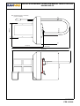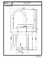
1
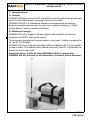
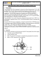
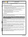
© KANNAD: This document is the property of KANNAD and contains proprietary and confidential information.
The document is loaned on the express condition that neither the document itself nor the information contained therein shall be disclosed without the express consent of KANNAD and that the information shall
not be used by the recipient without prior written acceptance by KANNAD. Furthermore, the document shall be returned immediately to KANNAD upon request.
DMA176J
Ref. 0139179J
Emergency Locator Transmitters by
INSTALLATION MANUAL
OPERATION MANUAL
INSPECTION LOG
KANNAD 406 AS
P/N : S1823502-02
P/N : S1823502-03
P/N : S1820514-14
P/N : S1820511-02
P/N : S1820511-03
P/N : S1820511-03
Revision 08
First issue: SEP 02/1999
ELT, KANNAD 406 AS (BNC)
ELT, KANNAD 406 AS (TNC)
WATER SWITCH SENSOR
MOUNTING BRACKET, AS
CARRY-OFF BAG, AS
CARRY-OFF BAG, Short
TP PAGE : 1
Date of rev. FEB 01/2008
Users are kindly requested to notify KANNAD of any discrepancy,
omission or error found in this manual.
Please report to our customer support:
E-mail: [email protected]
Tel.: +33 (0)2 97 02 49 00
INSTALLATION MANUAL OPERATION MANUAL INSPECTION LOG
KANNAD 406 AS
RECORD OF REVISIONS
REV. Nb REVISION DATE
INSERTION DATE
BY
01
02
03
04
MAR 18/2004
MAR 18/2004
J. S.
05
JAN 17/2005
JAN 17/2005
J. S.
06
JUN 27/2005
JUN 27/2005
J. S.
07
NOV 08/2006
NOV 08/2006
J. S.
08
FEB 01/2008
FEB 01/2008
J. S.
ROR PAGE: 1
FEB 01/2008
INSTALLATION MANUAL OPERATION MANUAL INSPECTION LOG
KANNAD 406 AS
RECORD OF REVISIONS
PAGE INTENTIONALLY LEFT BLANK
ROR PAGE: 2
FEB 01/2008
INSTALLATION MANUAL OPERATION MANUAL INSPECTION LOG
KANNAD 406 AS
LIST OF EFFECTIVE PAGES
SUBJECT
PAGE
DATE
Title Page
TP
1
FEB 01/2008
ROR
1
FEB 01/2008
ROR
2
FEB 01/2008
LEP
1
FEB 01/2008
LEP
2
FEB 01/2008
LEP
3
FEB 01/2008
LEP
4
FEB 01/2008
TOC
1
FEB 01/2008
TOC
2
FEB 01/2008
INTRO
1
FEB 01/2008
INTRO
2
FEB 01/2008
1
FEB 01/2008
2
FEB 01/2008
3
FEB 01/2008
4
FEB 01/2008
101
FEB 01/2008
102
FEB 01/2008
103
FEB 01/2008
104
FEB 01/2008
Record of Revisions
List of Effective Pages
Table of Contents
Introduction
System Overview
System Functional Description and Operation
LEP PAGE: 1
FEB 01/2008
INSTALLATION MANUAL OPERATION MANUAL INSPECTION LOG
KANNAD 406 AS
LIST OF EFFECTIVE PAGES
SUBJECT
PAGE
DATE
105
FEB 01/2008
106
FEB 01/2008
201
FEB 01/2008
202
FEB 01/2008
203
FEB 01/2008
204
FEB 01/2008
205
FEB 01/2008
206
FEB 01/2008
207
FEB 01/2008
208
FEB 01/2008
209
FEB 01/2008
210
FEB 01/2008
301
FEB 01/2008
302
FEB 01/2008
401
FEB 01/2008
402
FEB 01/2008
501
FEB 01/2008
502
FEB 01/2008
503
FEB 01/2008
504
FEB 01/2008
601
FEB 01/2008
Installation / Removal
Check
Troubleshooting
Schematics and Diagrams
Servicing
LEP PAGE: 2
FEB 01/2008
INSTALLATION MANUAL OPERATION MANUAL INSPECTION LOG
KANNAD 406 AS
LIST OF EFFECTIVE PAGES
SUBJECT
PAGE
DATE
602
FEB 01/2008
603
FEB 01/2008
604
FEB 01/2008
605
FEB 01/2008
606
FEB 01/2008
607
FEB 01/2008
608
FEB 01/2008
609
FEB 01/2008
610
FEB 01/2008
611
FEB 01/2008
612
FEB 01/2008
613
FEB 01/2008
614
FEB 01/2008
LEP PAGE: 3
FEB 01/2008
INSTALLATION MANUAL OPERATION MANUAL INSPECTION LOG
KANNAD 406 AS
LIST OF EFFECTIVE PAGES
PAGE INTENTIONALLY LEFT BLANK
LEP PAGE: 4
FEB 01/2008
INSTALLATION MANUAL OPERATION MANUAL INSPECTION LOG
KANNAD 406 AS
TABLE OF CONTENTS
INTRODUCTION ..................................................................................... 1
SYSTEM OVERVIEW ............................................................................. 1
COSPAS-SARSAT System ................................................................... 1
Description ............................................................................................................. 1
World coverage with the COSPAS-SARSAT system ............................................ 2
Environmental improvements of ELTs ................................................................... 2
KANNAD 406 AS Presentation ............................................................. 3
Design features ..................................................................................... 4
General .................................................................................................................. 4
Mechanical design .................................................................................................. 4
SYSTEM FUNCTIONAL DESCRIPTION AND OPERATION ............ 101
Transmitter ........................................................................................ 101
Controls ............................................................................................. 101
Working mode information ................................................................ 102
Autonomy .......................................................................................... 102
Technical Specifications .................................................................... 103
Manual Activation .............................................................................. 104
Water Switch Activation .................................................................... 105
Reset ................................................................................................. 106
INSTALLATION / REMOVAL ............................................................. 201
Registration and Programming ......................................................... 201
Pin programming option .................................................................................... 201
Installation ......................................................................................... 203
Installation with Carry-Off Bag ........................................................................... 203
Packing instructions ........................................................................................ 203
Installation with mounting bracket ...................................................................... 204
Bracket installation .......................................................................................... 204
ELT installation ................................................................................................ 204
Sealing ............................................................................................................ 207
Removal ............................................................................................ 208
Deployment from carry-off bag .......................................................................... 208
Deployment from mounting bracket ................................................................... 209
CHECK ................................................................................................ 301
Self-test ............................................................................................. 301
Periodicity .......................................................................................................... 301
Self-test procedure ............................................................................................ 301
TROUBLESHOOTING ........................................................................ 401
General ............................................................................................. 401
Faults on Self-test ............................................................................. 401
Visual Indicator .................................................................................................. 401
3+1 flashes ...................................................................................................... 401
TOC PAGE: 1
FEB 01/2008
INSTALLATION MANUAL OPERATION MANUAL INSPECTION LOG
KANNAD 406 AS
TABLE OF CONTENTS
3+2 flashes ..................................................................................................... 401
3+3 flashes ..................................................................................................... 401
3+4 flashes ..................................................................................................... 401
Other faults detected ......................................................................... 401
Buzzer ............................................................................................................... 401
Buzzer does not operate ................................................................................. 401
Buzzer operates permanently when ELT in ARM mode ................................. 401
SCHEMATICS & DIAGRAMS ............................................................ 501
Outline Dimensions ........................................................................... 501
Drilling Mask ..................................................................................... 503
SERVICING ........................................................................................ 601
Maintenance Schedule ..................................................................... 601
Periodic inspection ............................................................................................ 601
Every 6 years .................................................................................................... 601
Battery replacement .......................................................................................... 602
Periodic Inspection Log ............................................................ 603 / 608
Programming Log .................................................................... 609 / 613
Pre-delivery Inspection Log .............................................................. 614
TOC PAGE: 2
FEB 01/2008
INSTALLATION MANUAL OPERATION MANUAL INSPECTION LOG
KANNAD 406 AS
INTRODUCTION
The instructions in this manual provide the information necessary for the
installation and the operation of the KANNAD 406 AS ELT.
Servicing instructions are normally performed by shop personnel.
For servicing and maintenance instructions, refer to CMM 25-63-01.
FOR REGULATORY REQUIREMENTS, PLEASE CONSULT YOUR
NATIONAL AVIATION AUTHORITY.
PAGE INTRO 1
FEB 01/2008
INSTALLATION MANUAL OPERATION MANUAL INSPECTION LOG
KANNAD 406 AS
PAGE INTENTIONALLY LEFT BLANK
PAGE INTRO 2
FEB 01/2008
INSTALLATION MANUAL OPERATION MANUAL INSPECTION LOG
KANNAD 406 AS
SYSTEM OVERVIEW
1. COSPAS-SARSAT System
A. Description
Launched in the early eighties by the four founder countries (Canada, France,
Russia, USA), the COSPAS-SARSAT system provides satellite aid to search
and rescue (SAR) operations for maritime, aeronautical and terrestrial vehicles
anywhere in the world.
It uses distress beacons fitted on mobiles and a constellation of LEO and GEO
satellites which relay the 121.5 / 243 MHz signals and process the 406 MHz
signal to ground stations (LUT) where the beacon positions are determined
(with a precision of 10 NM with 121.5 / 243 signals and less than 2 NM with 406
signals).
Several types of beacons are designed to match the various applications of the
COSPAS-SARSAT system:
• EPIRB (Emergency Position Indicating Radio Beacon) for maritime
applications.
• ELT (Emergency Locator Transmitter) for aeronautical applications.
• PLB (Personal Locator Beacon) for land expeditions.
Figure 1: COSPAS-SARSAT System
PAGE 1
FEB 01/2008
INSTALLATION MANUAL OPERATION MANUAL INSPECTION LOG
KANNAD 406 AS
B. World coverage with the COSPAS-SARSAT system
The major improvement is the use of the COSPAS-SARSAT system for
processing aeronautical emergencies.
The difference with the 121.5 / 243 MHz is that the 406 MHz transmission
carries digital data which enable the identification of the aircraft in distress and
facilitate SAR operation (type of the aircraft, number of passengers, type of
emergency).
The 406 MHz message is transmitted to the COSPAS-SARSAT satellites. This
message is downloaded to one of the 64 ground stations (44 LEOLUTs and 20
GEOLUTS).
The aircraft is located by Doppler effect by the LEO satellites with a precision
better than 2 NM (4 km) at any point of the earth.
C. Environmental improvements of ELTs
The certification of an ELT includes a range of severe mechanical tests:
• resistance to flame;
• impact and crush tests;
• resistance to 100 G and 500 G shocks;
• watertightness;
• antideflagration;
• extreme temperatures (-20°C to 55°C for more than 48 hours);
PAGE 2
FEB 01/2008
INSTALLATION MANUAL OPERATION MANUAL INSPECTION LOG
KANNAD 406 AS
2. KANNAD 406 AS Presentation
The KANNAD 406 AS is composed of:
1.
a transmitter;
2.
an optional mounting bracket (2a) and locking pin (2b);
3.
a float;
4.
an auxiliary antenna;
5.
a water switch sensor (option);
6.
a "Programming Dongle" for pin-programming function (option).
4
5 or
A
N
T
TS
T
O
6
2a
FF
O
N
R
C
3
1
2b
Figure 2: KANNAD 406 AS presentation
PAGE 3
FEB 01/2008
INSTALLATION MANUAL OPERATION MANUAL INSPECTION LOG
KANNAD 406 AS
3. Design features
A. General
KANNAD 406 AS is a survival ELT intended to be removed from the aircraft and
used to assist SAR teams in locating survivors of a crash.
KANNAD 406 AS is a standalone equipment equipped with an auxiliary
antenna and activated manually by survivors or automatically by a "Water
Switch Sensor" when in contact with water.
B. Mechanical design
KANNAD 406 AS is made of moulded plastic with excellent mechanical
resistance (ASA/PC, light yellow colour).
The housing is designed to be easily taken in one hand. A tether is supplied to
tie the ELT to a liferaft.
KANNAD 406 AS is fitted with a floating collar to enable the ELT to float upright
if used in water. This floating collar can be removed if the ELT is attached to a
life-raft or any buoyant part.
Important notice: Unlike all other KANNAD 406 ELTs (automatic),
KANNAD 406 AS (survival) is not fitted with a G-Switch (shock detector).
Figure 3: KANNAD 406 AS
PAGE 4
FEB 01/2008
INSTALLATION MANUAL OPERATION MANUAL INSPECTION LOG
KANNAD 406 AS
SYSTEM FUNCTIONAL DESCRIPTION AND OPERATION
1. Transmitter
The KANNAD 406 AS is designed to transmit on three frequencies (121.5, 243
and 406 MHz).The two basic aeronautical emergency frequencies (121.5 and
243 MHz ) are mainly used for homing in the final stages of the rescue
operations. The 406 MHz frequency is used by the COSPAS-SARSAT
satellites for precise pinpointing and identification of the aircraft in distress.
Once activated, the transmitter operates continuously on 121.5 and 243 MHz.
The output power is 100 mW on each frequency.
The modulation is an audio frequency sweeping downwards from 1420 Hz to
490 Hz with a repetition rate of 4 Hz. The AM modulation factor is between 85
and 100%.
During the 24 first hours of operation, a signal is transmitted on 406 MHz every
50 seconds to the COSPAS-SARSAT satellites. The output power on 406 MHz
is near 5W i.e. 50 times more powerful than the VHF signal.
Phase modulation at 400 bps enables transmission of all the relevant
identification information to the COSPAS-SARSAT satellites in less than half a
second.
2. Controls
The following controls are to be found on the ELT front panel (from left to right):
1.
3-position switch ARM/OFF/ON;
2.
Visual indicator (red);
3.
DIN 12 connector for dongle or programming equipment connection;
4.
BNC or TNC connector for the antenna.
4
Ant
Arm Off On
1
RC
2
3
PAGE 101
FEB 01/2008
INSTALLATION MANUAL OPERATION MANUAL INSPECTION LOG
KANNAD 406 AS
Figure 101: Front Panel
3. Working mode information
The visual indicator gives an indication on the working mode of the beacon:
• after the self test, a series of short flashes indicates the self test failed, one
long flash indicates that the self test is OK.
• in operating mode, periodic flashes during 121,5 / 243 transmission and
one long flash during every 406 burst (1 every 50 seconds).
A buzzer gives aural information on the working mode of the beacon:
• continuous tone during self test;
• 2 beeps per second during 121.5 / 243 transmission;
• silence during 406 transmission.
4. Autonomy
The energy is provided by a battery pack composed of 3 LiMnO2 D cells (See
pages 103 & 602 for Kit battery reference).
Lithium cells, lithium batteries and equipment containing such
batteries are subjected to regulations and classified under class 9 as
from 1st of January 2003.
The autonomy of the 121.5/243 transmission is close to 100 hours at -20°C with
new batteries.
In the worse conditions possible, a distress is pinpointed 5.5 hours maximum
after the ELT activation and the position is subsequently updated (if necessary)
every 2 hours.
As it is therefore preferable to keep the battery power for 121.5/243 MHz
homing frequency transmission for the rescue operations, the 406 MHz
transmission is deliberately stopped after 24 hours to extend the 121.5/243
transmission for as long as possible.
The transmitter battery expiry date is fixed at 6 years after manufacturing. If no
activation of the ELT occurs during the battery lifetime, it shall be replaced
every 6 years(see note below).
NOTE: The useful life time of batteries is twelve (12) years. To be in compliance
with FAR regulations, they have to be replaced every (6) years when 50
percent of their useful life has expired.
PAGE 102
FEB 01/2008
INSTALLATION MANUAL OPERATION MANUAL INSPECTION LOG
KANNAD 406 AS
5. Technical Specifications
TYPE
• Three-frequency ELT
(121.5 / 243,0 / 406,025 MHz)
• Survival
• COSPAS-SARSAT Class II
(-20°C to +55°C)
406 MHz TRANSMISSION
• Frequency: 406.025 Mhz+/-2 kHz
• Output power: 5W (37 dBm +/- 2 dB)
• Modulation type: 16K0G1D (Biphase
L encoding)
• Transmission duration:
440ms (short message) every 50 sec.
• Autonomy: Over 24 hours at
-20°C
121,5/243 MHz TRANSMISSION
• Frequencies:
121.5 MHz +/- 6 kHz
243.0 MHz +/- 12 kHz
• Output power:100 to 400 mW (20dBm
to 26 dBm)
for each frequency
• Modulation type: 3K20A3X
• Modulation rate: between 85 and
100%
• Frequency of modulation signal:
1420 Hz to 490 Hz with decreasing
sweep
• Autonomy: Over 48 hours at
-20°C
CONTROLS
• ARM / OFF / ON switch
• Red visual indicator
• BNC antenna connector (S182350202)
• TNC antenna connector (S182350203)
• DIN12 connector for remote control,
pin programming option and water
switch sensor option
• Buzzer
BATTERY
KIT BAT300, P/N : S1820516-99
3 x LiMnO2 D type cells for transmitter
power supply
Replacement every 6 years
HOUSING
Material: Molded plastic
Color: Yellow
Tightness: O-rings
Flotation: Yellow foam Ø160mm ± 5mm
(6.3 In. ± 0.196 In.)
Transmitter dimensions:
• 172 mm x 82 mm x 82 mm
(6.77 x 3.228 x 3.228 In.)
Overall dimensions (antenna deployed):
• max 590 mm x 160 mm x 160 mm
(23.228 x 6.3 x 6.3 In.)
Packed dimensions (in carry-off bag):
• Carry-off bag AS:
- 332 mm x 180 mm x 180 mm
(13.07 x 7.086 x 7.086 In.)
• Carry-off bag Short:
- 290 mm x 180 mm x 180 mm
(11.417 x 7.086 x 7.086)
Stowed dimensions (mounting bracket):
• 300 mm x 162 mm x 160 mm
(11.81 x 6.377 x 6.3 In)
Weight (incl. Auxiliary antenna, floating
collar and batteries):
• typical 1180 g / max 1250 g
(2.6 lb / 2.75 lb)
Weight (mounting bracket):
• typical 165 g / max 175 g
(0.36 lb / 0.38 lb)
ENVIRONMENTAL CONDITIONS
RTCA DO-160 Ch. 4 to25
[ED62]XBA[ED62][RCC1]AWXXXXZXXX
ZWL[(A1)(A2)(A3)XX]XXA
QUALIFICATIONS
JTSO-2C91a & JTSO-2C126 (EUROCAE
ED62)
TSO-C91a & TSO-C126 (RTCA DO183 &
DO204)
PAGE 103
FEB 01/2008
INSTALLATION MANUAL OPERATION MANUAL INSPECTION LOG
KANNAD 406 AS
6. Manual Activation
• Switch to "ON" position.
Switch ON
ANT
TST
OFF
ON
RC
• Try to keep the antenna vertical.
- The ELT starts with the self-test sequence.
- 121.5 / 243 MHz transmission starts immediately after the self-test.
- 406 MHz transmission starts after 50 seconds.
- During transmission, buzzer operates and visual indicator flashes
periodically.
PAGE 104
FEB 01/2008
INSTALLATION MANUAL OPERATION MANUAL INSPECTION LOG
KANNAD 406 AS
7. Water Switch Activation
The ELT switch must be in the "ARM" position and the Water Switch
Sensor must be connected.
Fasten the ELT to the liferaft with the tether line.
Put the ELT in the water to float safely.
Check that buzzer operates and visual indicator flashes
periodically.
The ELT should float with
antenna in vertical position
PAGE 105
FEB 01/2008
INSTALLATION MANUAL OPERATION MANUAL INSPECTION LOG
KANNAD 406 AS
8. Reset
In case of unintentional activation, the ELT can be stopped manually.
No transmission must be interrupted unless every means are used to
contact and inform the Air Traffic Controller of this action.
Important notice : As 406 MHz transmission is effective 50 seconds after
the ELT activation, if it is reset within this delay, no further radio contact
will be necessary.
• Switch to " OFF ".
Switch OFF
ANT
TST
OFF
ON
RC
PAGE 106
FEB 01/2008
INSTALLATION MANUAL OPERATION MANUAL INSPECTION LOG
KANNAD 406 AS
INSTALLATION / REMOVAL
1. Registration and Programming
The ELT must be registered prior to installation on board.
The registration card available from the local registration authority
must be completed and returned to this authority.
The "Programming Datasheet" (DIM0300) must be completed and
returned to your distributor.
Any change of ownership shall also be declared and registered with
the local registration authority and with the distributor.
The KANNAD 406 AS is fully compatible with the four programming protocols
defined by the COSPAS-SARSAT C/S G005 document:
• Serialised Number.
• Aircraft 24 bit Address (the same as MODE S ATC or TCAS).
• Aircraft Operator Designator + serialised number up to 4096.
• Aircraft Nationality and Registration marking (Tail Number). This
identification consists of up to 7 alphanumeric characters.
Programming of the ELT can be carried out either:
• by KANNAD or the distributor (order must include programming details).
• in the shop with programming and test equipment (PC interface and DOS
or Windows® software).
• on board the aircraft with a programming equipment or programming
dongle.
This operation takes less than 2 minutes and does not need any hardware
operation. The identification is simply downloaded to the ELT when connected
to the KANNAD programming equipment via the DIN 12 connector.
A. Pin programming option
The KANNAD 406 AS offers pin-programming capabilities to facilitate
maintenance operations especially in the case of removals and/or
replacement.
A special DIN 12 connector with a Serial Memory Module (called "Programming
Dongle") is connected to the ELT when installed on board. This Programming
Dongle contains the identification information of the aircraft and remains on
board the aircraft. When an unprogrammed ELT is installed and connected to
this Programming Dongle and the "ELT" is switched to "ARM", it automatically
PAGE 201
FEB 01/2008
INSTALLATION MANUAL OPERATION MANUAL INSPECTION LOG
KANNAD 406 AS
updates its own memory with the identification data contained in the
Programming Dongle memory.
When the ELT is removed from the aircraft, it keeps its identification data.
For maintenance purposes, it is possible to delete the identification information
of the ELT by connecting a "Maintenance Dongle" to the ELT. Any accidental
transmission with this "maintenance dongle" will not involve SAR operation as
the identification code transmitted is recognised by COSPAS-SARSAT as "not
on board".
When a maintenance dongle is connected:
• Country code is 227 (France).
• Protocol is Test.
• Identification number is SI + 5 digits (the last 5 digits of CSN number).
If the pin programming option is selected by the operator, the following
equipment are required:
• a "Programming Dongle" on each aircraft;
• a "Maintenance Dongle" on each ELT spare.
Figure 201: Maintenance Dongle
PAGE 202
FEB 01/2008
INSTALLATION MANUAL OPERATION MANUAL INSPECTION LOG
KANNAD 406 AS
2. Installation
"The location of the ELT shall be chosen to minimise the potential for
inadvertent activation, damage by impact, fire and contact by passengers or
baggage" (RTCA DO-183)
"The ELT must be attached to the aircraft in such a manner that the probability
of damage to the transmitter in the event of a crash impact is minimised." (FAR
91.207)
The ELT shall not be installed less than 60 cm (2 ft) from a magnetic field
sensor.
The KANNAD 406 AS can be either packed in a carry off bag or installed on a
mounting bracket.
A. Installation with Carry-Off Bag
The KANNAD 406 AS is packed in a carry off bag with 3 handles for easy
handling.
(1)Packing instructions
• Check that the switch is in the "OFF" position ("ARM" if the beacon is fitted
with a water switch sensor).
• Slide the antenna though the hole provided in floating collar.
• Put the ELT with the antenna downwards so that it fits on lower part of the
wedging foam.
• Turn it ¼ turn so that the antenna fits between top and bottom wedging
foam.
• The ELT should wedge into place.
Figure 202: Packing Instructions
PAGE 203
FEB 01/2008
INSTALLATION MANUAL OPERATION MANUAL INSPECTION LOG
KANNAD 406 AS
B. Installation with mounting bracket
(1)Bracket installation
• Determine the location of the ELT on board according to FAR/RTCA
recommendations.
• Drill 3 holes Ø 5,5 mm in the aircraft structure according to "Drilling mask"
page 503 of this document.
• Fix the bracket with the 3 screws and nylstop nuts or 3 rivets.
(2) ELT installation
• Check that the ELT identification label matches the aircraft tail number.
• If the mounting bracket is fitted with a Programming Dongle (P/N
S1820514-01), remove the Water Switch Sensor connector and connect
the programming dongle to the ELT.
Ant
Ant
Arm Off On
Arm Off On
RC
RC
• Perform a Self-test (see paragraph "SELF-TEST").
• If test result is OK, switch back to "OFF".
• Disconnect the Programming
Dongle (if applicable) and stow
it in the compartment designed
to this effect inside the bracket.
PAGE 204
FEB 01/2008
INSTALLATION MANUAL OPERATION MANUAL INSPECTION LOG
KANNAD 406 AS
• Reconnect the Water Switch Sensor (if applicable).
• Slide the antenna through the hole provided in the floating collar.
• Slide the locking pin as shown hereunder.
Ant
Arm Off On
A nt Arm Off
OnRC
RC
PAGE 205
FEB 01/2008
INSTALLATION MANUAL OPERATION MANUAL INSPECTION LOG
KANNAD 406 AS
• Install the ELT on the mounting bracket with "lower cover" facing the
mounting bracket.
• Fasten the Velcro® strap tightly.
• If the ELT is fitted with a Water Switch Sensor (P/N S1820514-14), switch
the ELT to the "ARM" position.
PAGE 206
FEB 01/2008
INSTALLATION MANUAL OPERATION MANUAL INSPECTION LOG
KANNAD 406 AS
(3) Sealing
It is possible to seal the ELT on its bracket to prevent misuse.
In case of an emergency, this seal must be weak enough to be broken manually
without any special tool.
ELT shall be installed with locking pin so that switch cannot be put in the "ON"
position (see Installation).
• Install a seal using one of the two holes in the cover of the ELT and the
mounting bracket.
PAGE 207
FEB 01/2008
INSTALLATION MANUAL OPERATION MANUAL INSPECTION LOG
KANNAD 406 AS
3. Removal
A. Deployment from carry-off bag
The ELT shall only be deployed in a safe area.
• Press the buckles to open the bag top cover.
• Turn the ELT sideways to release it from the
wedging form.
• Deploy the antenna and check that it is
connected correctly.
PAGE 208
FEB 01/2008
INSTALLATION MANUAL OPERATION MANUAL INSPECTION LOG
KANNAD 406 AS
B. Deployment from mounting bracket
• Unfasten the Velcro® strap.
• Remove the ELT with the antenna from the bracket.
• The locking pin will be extracted from the ELT while remaining attached to
the mounting bracket.
• If,unfortunately, the locking pin was not extracted, slide it to have free
access to the switch.
Ant
Arm Off On
RC
PAGE 209
FEB 01/2008
INSTALLATION MANUAL OPERATION MANUAL INSPECTION LOG
KANNAD 406 AS
• Deploy the antenna and check that it is connected correctly.
PAGE 210
FEB 01/2008
INSTALLATION MANUAL OPERATION MANUAL INSPECTION LOG
KANNAD 406 AS
CHECK
1. Self-test
A. Periodicity
It is recommended by the manufacturer to test the ELT to detect any possible
failure.
It is recommended to perform a self-test once a month but it should not be
done more than once a week.
However, each self-test consumes energy from the battery. Should self-tests
be carried out more often than the maximum allowed, the battery life-time might
be shorter than specified.
Do not perform Self-test without the antenna connected.
B. Self-test procedure
• Check that the antenna is connected correctly.
• If a programming dongle is fitted on the bracket, connect it to the ELT.
• Switch the ELT from "OFF" to "ARM".
• The buzzer operates during the whole Self-test procedure.
• After a few seconds, the test result is displayed with the visual indicator as
follows:
- One long flash indicates that the beacon is operational and that no error
conditions were found.
- A series of short flashes indicates test failed.
• Switch back to "OFF" (or keep in the "ARM" position if the ELT is equipped
with a water switch sensor).
If self-test fails, contact the distributor as soon as possible.
Unless a waver is granted, flight should be cancelled.
Remark: The number of flashes gives an indication of the faulty
parameter detected during the self-test.
3+1
LOW BATTERY VOLTAGE
3+2
LOW RF POWER
3+3
FAULTY VCO LOCKING (FAULTY FREQUENCY)
3+4
NO IDENTIFICATION PROGRAMMED
PAGE 301
FEB 01/2008
INSTALLATION MANUAL OPERATION MANUAL INSPECTION LOG
KANNAD 406 AS
PAGE INTENTIONALLY LEFT BLANK
PAGE 302
FEB 01/2008
INSTALLATION MANUAL OPERATION MANUAL INSPECTION LOG
KANNAD 406 AS
TROUBLESHOOTING
1. General
Procedure for fault isolation on board uses the visual indicator of the ELT’s front
panel. This visual indicator is activated by a self-test capability within the ELT.
2. Faults on Self-test
A. Visual Indicator
When the self-test is carried out, the number of flashes gives an indication of
the faulty parameter detected during the self-test.
(1)3+1 flashes
- Low battery voltage:
Check battery, refer to CMM 25-63-01 for repair(see note 1 below).
(2) 3+2 flashes
- Low RF power:
Check 406 MHz power, refer to CMM 25-63-01 for repair(see note 1 below).
(3) 3+3 flashes
- Faulty VCO locking (faulty frequency):
Check 406 MHz frequency, refer to CMM 25-63-01 for repair(see note 1
below).
(4) 3+4 flashes
- No identification programmed
Check programming(see note 2 below).
- NOTE: (1) Only PART/FAR 145 certified stations accredited by
KANNAD can perform these repairs.
(2) Only accredited programming stations can perform
programming.
3. Other faults detected
A. Buzzer
(1)Buzzer does not operate
- Refer to CMM 25-63-01 for repair(see note 1 above).
(2) Buzzer operates permanently when ELT in ARM mode
- Refer to CMM 25-63-01 for repair(see note 1 above).
PAGE 401
FEB 01/2008
INSTALLATION MANUAL OPERATION MANUAL INSPECTION LOG
KANNAD 406 AS
PAGE INTENTIONALLY LEFT BLANK
PAGE 402
FEB 01/2008
INSTALLATION MANUAL OPERATION MANUAL INSPECTION LOG
KANNAD 406 AS
SCHEMATICS & DIAGRAMS
1. Outline Dimensions
Note: all dimensions are in millimeters
(inches in brackets)
PAGE 501
FEB 01/2008
INSTALLATION MANUAL OPERATION MANUAL INSPECTION LOG
KANNAD 406 AS
Note: all dimensions are in millimeters
(inches in brackets)
160 (6.23)
86 (3.38)
172 (6.77)
300 (11.97)
300 (11.97)
162 (6.38)
PAGE 502
FEB 01/2008
INSTALLATION MANUAL OPERATION MANUAL INSPECTION LOG
KANNAD 406 AS
Note: all dimensions are in millimeters
(inches in brackets)
2. Drilling Mask
PAGE 503
FEB 01/2008
INSTALLATION MANUAL OPERATION MANUAL INSPECTION LOG
KANNAD 406 AS
PAGE INTENTIONALLY LEFT BLANK
PAGE 504
FEB 01/2008
INSTALLATION MANUAL OPERATION MANUAL INSPECTION LOG
KANNAD 406 AS
SERVICING
1. Maintenance Schedule
Periodic inspection and battery replacement can only be carried out by
an accredited PART or FAR 145 maintenance station with valid
agreement for KANNAD ELT maintenance.
A. Periodic inspection
Note: (if required by the relevant Civil Aviation Authority).
Some Civil Aviation Authorities may require the ELT is tested periodically. In
this case, KANNAD recommends to check the following parameters:
• Battery voltage.
• 121.5 MHz / 243.0 MHz / 406.025 MHz transmission power.
• 121.5 MHz / 243.0 MHz / 406.025 MHz frequency.
• VCO lock.
• 121.5 MHz AM decoding (sweep monitoring with VHF receiver).
• Number of 406 MHz transmissions (optional, programming kit required).
• Number of self-tests carried out (optional, programming kit required).
• Programmed data (optional, programming kit required).
NOTE: This functioning check can be carried out without opening the
ELT.
B. Every 6 years
Testing of the various elements of the ELT is mandatory every 6 years together
with the battery replacement.
• Visual control of the housing and accessories
CMM 25-63-01.
• O-ring, battery and desiccant capsule replacement
CMM 25-63-01.
• Beacon Tightness
CMM 25-63-01.
• "Testing and Fault Isolation" procedure as described in
CMM 25-63-01.
PAGE 601
FEB 01/2008
INSTALLATION MANUAL OPERATION MANUAL INSPECTION LOG
KANNAD 406 AS
C. Battery replacement
Battery replacement is mandatory:
• after more than 1 hour of real transmission (cumulated duration);
• before or on the battery expiration date.
Only original battery pack included in battery kit
(KIT BAT 300, P/N S1820516-99)
supplied by KANNAD can be installed.
KANNAD refuse all responsibility and invalidate
all warranty should other packs be installed.
PAGE 602
FEB 01/2008
INSTALLATION MANUAL OPERATION MANUAL INSPECTION LOG
KANNAD 406 AS
2. Periodic Inspection Log
Type of inspection :
Periodic ..
Battery change ..
Repair..
Other
Operations carried out (*) :
Next recommended inspection date : _ _ / _ _ _ _
Next planned battery replacement (mandatory) date : _ _ / _ _ _ _
Date : _ _ / _ _ / _ _ _ _
Service station :
Signature and stamp :
Type of inspection :
Periodic ..
Battery change ..
Repair..
Other
Operations carried out (*) :
Next recommended inspection date : _ _ / _ _ _ _
Next planned battery replacement (mandatory) date : _ _ / _ _ _ _
Date : _ _ / _ _ / _ _ _ _
Service station :
Signature and stamp :
(*) note complete P/N of replaced components (if battery pack has been changed, also note
Batch Number, Tester Name and Date of Manufacture).
PAGE 603
FEB 01/2008
INSTALLATION MANUAL OPERATION MANUAL INSPECTION LOG
KANNAD 406 AS
3. Periodic Inspection Log
Type of inspection :
Periodic ..
Battery change ..
Repair..
Other
Operations carried out (*) :
Next recommended inspection date : _ _ / _ _ _ _
Next planned battery replacement (mandatory) date : _ _ / _ _ _ _
Date : _ _ / _ _ / _ _ _ _
Service station :
Signature and stamp :
Type of inspection :
Periodic ..
Battery change ..
Repair..
Other
Operations carried out (*) :
Next recommended inspection date : _ _ / _ _ _ _
Next planned battery replacement (mandatory) date : _ _ / _ _ _ _
Date : _ _ / _ _ / _ _ _ _
Service station :
Signature and stamp :
(*) note complete P/N of replaced components (if battery pack has been changed, also note
Batch Number, Tester Name and Date of Manufacture).
PAGE 604
FEB 01/2008
INSTALLATION MANUAL OPERATION MANUAL INSPECTION LOG
KANNAD 406 AS
4. Periodic Inspection Log
Type of inspection :
Periodic ..
Battery change ..
Repair..
Other
Operations carried out (*) :
Next recommended inspection date : _ _ / _ _ _ _
Next planned battery replacement (mandatory) date : _ _ / _ _ _ _
Date : _ _ / _ _ / _ _ _ _
Service station :
Signature and stamp :
Type of inspection :
Periodic ..
Battery change ..
Repair..
Other
Operations carried out (*) :
Next recommended inspection date : _ _ / _ _ _ _
Next planned battery replacement (mandatory) date : _ _ / _ _ _ _
Date : _ _ / _ _ / _ _ _ _
Service station :
Signature and stamp :
(*) note complete P/N of replaced components (if battery pack has been changed, also note
Batch Number, Tester Name and Date of Manufacture).
PAGE 605
FEB 01/2008
INSTALLATION MANUAL OPERATION MANUAL INSPECTION LOG
KANNAD 406 AS
5. Periodic Inspection Log
Type of inspection :
Periodic ..
Battery change ..
Repair..
Other
Operations carried out (*) :
Next recommended inspection date : _ _ / _ _ _ _
Next planned battery replacement (mandatory) date : _ _ / _ _ _ _
Date : _ _ / _ _ / _ _ _ _
Service station :
Signature and stamp :
Type of inspection :
Periodic ..
Battery change ..
Repair..
Other
Operations carried out (*) :
Next recommended inspection date : _ _ / _ _ _ _
Next planned battery replacement (mandatory) date : _ _ / _ _ _ _
Date : _ _ / _ _ / _ _ _ _
Service station :
Signature and stamp :
(*) note complete P/N of replaced components (if battery pack has been changed, also note
Batch Number, Tester Name and Date of Manufacture).
PAGE 606
FEB 01/2008
INSTALLATION MANUAL OPERATION MANUAL INSPECTION LOG
KANNAD 406 AS
6. Periodic Inspection Log
Type of inspection :
Periodic ..
Battery change ..
Repair..
Other
Operations carried out (*) :
Next recommended inspection date : _ _ / _ _ _ _
Next planned battery replacement (mandatory) date : _ _ / _ _ _ _
Date : _ _ / _ _ / _ _ _ _
Service station :
Signature and stamp :
Type of inspection :
Periodic ..
Battery change ..
Repair..
Other
Operations carried out (*) :
Next recommended inspection date : _ _ / _ _ _ _
Next planned battery replacement (mandatory) date : _ _ / _ _ _ _
Date : _ _ / _ _ / _ _ _ _
Service station :
Signature and stamp :
(*) note complete P/N of replaced components (if battery pack has been changed, also note
Batch Number, Tester Name and Date of Manufacture).
PAGE 607
FEB 01/2008
INSTALLATION MANUAL OPERATION MANUAL INSPECTION LOG
KANNAD 406 AS
7. Periodic Inspection Log
Type of inspection :
Periodic ..
Battery change ..
Repair..
Other
Operations carried out (*) :
Next recommended inspection date : _ _ / _ _ _ _
Next planned battery replacement (mandatory) date : _ _ / _ _ _ _
Date : _ _ / _ _ / _ _ _ _
Service station :
Signature and stamp :
Type of inspection :
Periodic ..
Battery change ..
Repair..
Other
Operations carried out (*) :
Next recommended inspection date : _ _ / _ _ _ _
Next planned battery replacement (mandatory) date : _ _ / _ _ _ _
Date : _ _ / _ _ / _ _ _ _
Service station :
Signature and stamp :
(*) note complete P/N of replaced components (if battery pack has been changed, also note
Batch Number, Tester Name and Date of Manufacture).
PAGE 608
FEB 01/2008
INSTALLATION MANUAL OPERATION MANUAL INSPECTION LOG
KANNAD 406 AS
8. Programming Log
Identification protocol :
TN ....
ICAO ....
AOD ....
S/N ....
TEST
ICAO ....
AOD ....
S/N ....
TEST
Identification number :
Beacon identification (15 HEX ID) :
Aircraft Tail Number :
Date : _ _ / _ _ / _ _ _ _
Service station :
Signature and stamp :
Identification protocol :
TN ....
Identification number :
Beacon identification (15 HEX ID) :
Aircraft Tail Number :
Date : _ _ / _ _ / _ _ _ _
Service station :
Signature and stamp :
PAGE 609
FEB 01/2008
INSTALLATION MANUAL OPERATION MANUAL INSPECTION LOG
KANNAD 406 AS
9. Programming Log
Identification protocol :
TN ....
ICAO ....
AOD ....
S/N ....
TEST
ICAO ....
AOD ....
S/N ....
TEST
Identification number :
Beacon identification (15 HEX ID) :
Aircraft Tail Number :
Date : _ _ / _ _ / _ _ _ _
Service station :
Signature and stamp :
Identification protocol :
TN ....
Identification number :
Beacon identification (15 HEX ID) :
Aircraft Tail Number :
Date : _ _ / _ _ / _ _ _ _
Service station :
Signature and stamp :
PAGE 610
FEB 01/2008
INSTALLATION MANUAL OPERATION MANUAL INSPECTION LOG
KANNAD 406 AS
10.Programming Log
Identification protocol :
TN ....
ICAO ....
AOD ....
S/N ....
TEST
ICAO ....
AOD ....
S/N ....
TEST
Identification number :
Beacon identification (15 HEX ID) :
Aircraft Tail Number :
Date : _ _ / _ _ / _ _ _ _
Service station :
Signature and stamp :
Identification protocol :
TN ....
Identification number :
Beacon identification (15 HEX ID) :
Aircraft Tail Number :
Date : _ _ / _ _ / _ _ _ _
Service station :
Signature and stamp :
PAGE 611
FEB 01/2008
INSTALLATION MANUAL OPERATION MANUAL INSPECTION LOG
KANNAD 406 AS
11.Programming Log
Identification protocol :
TN ....
ICAO ....
AOD ....
S/N ....
TEST
ICAO ....
AOD ....
S/N ....
TEST
Identification number :
Beacon identification (15 HEX ID) :
Aircraft Tail Number :
Date : _ _ / _ _ / _ _ _ _
Service station :
Signature and stamp :
Identification protocol :
TN ....
Identification number :
Beacon identification (15 HEX ID) :
Aircraft Tail Number :
Date : _ _ / _ _ / _ _ _ _
Service station :
Signature and stamp :
PAGE 612
FEB 01/2008
INSTALLATION MANUAL OPERATION MANUAL INSPECTION LOG
KANNAD 406 AS
12.Programming Log
Identification protocol :
TN ....
ICAO ....
AOD ....
S/N ....
TEST
ICAO ....
AOD ....
S/N ....
TEST
Identification number :
Beacon identification (15 HEX ID) :
Aircraft Tail Number :
Date : _ _ / _ _ / _ _ _ _
Service station :
Signature and stamp :
Identification protocol :
TN ....
Identification number :
Beacon identification (15 HEX ID) :
Aircraft Tail Number :
Date : _ _ / _ _ / _ _ _ _
Service station :
Signature and stamp :
PAGE 613
FEB 01/2008
INSTALLATION MANUAL OPERATION MANUAL INSPECTION LOG
KANNAD 406 AS
13.Pre-delivery Inspection Log
FIT DECAL HERE
P/N: ________-__
AMDT: _
S/N: 2615748- ____
CSN: 3_____
DOM: __/____
Controlled By: __
Next battery replacement before: __/____
Date : __/__/__
Stamp:
PAGE 614
FEB 01/2008
Distributed by
Manufactured by
KANNAD
Z.I. des Cinq Chemins BP23
56520 GUIDEL - FRANCE
Tél. / Phone : +33 (0) 2 97 02 49 49
Fax : +33 (0) 2 97 65 00 20
DMA176J
Ref: 0139179J