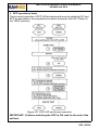
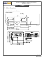
1
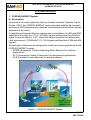
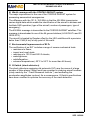
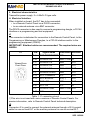
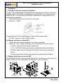
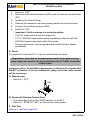
© KANNAD: This document is the property of KANNAD and contains proprietary and confidential information.
The document is loaned on the express condition that neither the document itself nor the information contained therein shall be disclosed without the express consent of KANNAD and that the information shall
not be used by the recipient without prior written acceptance by KANNAD. Furthermore, the document shall be returned immediately to KANNAD upon request.
DOC06330D
Ref. 0143020D
Emergency Locator Transmitter
INSTALLATION MANUAL
OPERATION MANUAL
KANNAD 406 AP-H
P/N : S1820502-04
P/N : S1820511-01
P/N : 0124206
Revision 03
First issue: OCT 18/2006
KANNAD 406 AP-H transmitter
Mounting bracket, 1 strap
ANT100, auxiliary antenna
TP PAGE : 1
Date of rev. APR 30/2010
Users are kindly requested to notify KANNAD of any discrepancy,
omission or error found in this manual.
Please report to our customer support:
E-mail: [email protected]
Tel.: +33 (0)2 97 02 49 00
INSTALLATION MANUAL OPERATION MANUAL
KANNAD 406 AP-H
RECORD OF REVISIONS
REV. Nb REVISION DATE
INSERTION DATE
BY
00
OCT 18/2006
OCT 18/2006
J. S.
01
FEB 13/2008
FEB 13/2008
J. S.
02
SEP 12/2008
SEP 12/2008
J. S.
03
APR 30/2010
APR 30/2010
J. S.
ROR PAGE: 1
APR 30/2010
INSTALLATION MANUAL OPERATION MANUAL
KANNAD 406 AP-H
RECORD OF REVISIONS
PAGE INTENTIONALLY LEFT BLANK
ROR PAGE: 2
APR 30/2010
INSTALLATION MANUAL OPERATION MANUAL
KANNAD 406 AP-H
LIST OF EFFECTIVE PAGES
SUBJECT
PAGE
DATE
Title Page
TP
1
APR 30/2010
ROR
1
APR 30/2010
ROR
2
APR 30/2010
LEP
1
APR 30/2010
LEP
2
APR 30/2010
TOC
1
APR 30/2010
TOC
2
APR 30/2010
TOC
3
APR 30/2010
TOC
4
APR 30/2010
INTRO
1
SEP 12/2008
INTRO
2
SEP 12/2008
1
SEP 12/2008
2
SEP 12/2008
3
APR 30/2010
4
SEP 12/2008
5
SEP 12/2008
6
APR 30/2010
7
APR 30/2010
8
APR 30/2010
Record of Revisions
List of Effective Pages
Table of Contents
Introduction
System Overview
System Functional Description and Operation
LEP PAGE: 1
SEP 12/2008
INSTALLATION MANUAL OPERATION MANUAL
KANNAD 406 AP-H
LIST OF EFFECTIVE PAGES
SUBJECT
PAGE
DATE
101
SEP 12/2008
102
SEP 12/2008
103
SEP 12/2008
104
SEP 12/2008
105
SEP 12/2008
106
SEP 12/2008
107
SEP 12/2008
108
SEP 12/2008
109
SEP 12/2008
110
SEP 12/2008
201
APR 30/2010
202
SEP 12/2008
203
APR 30/2010
204
APR 30/2010
205
SEP 12/2008
206
SEP 12/2008
207
APR 30/2010
208
APR 30/2010
209
APR 30/2010
210
APR 30/2010
301
SEP 12/2008
302
SEP 12/2008
303
SEP 12/2008
304
SEP 12/2008
Installation / Removal
Check
LEP PAGE: 2
SEP 12/2008
INSTALLATION MANUAL OPERATION MANUAL
KANNAD 406 AP-H
LIST OF EFFECTIVE PAGES
SUBJECT
PAGE
DATE
Troubleshooting
Schematics and Diagrams
401
SEP 12/2008
402
SEP 12/2008
501
SEP 12/2008
502
SEP 12/2008
503
SEP 12/2008
504
APR 30/2010
505
APR 30/2010
506
APR 30/2010
507
APR 30/2010
508
APR 30/2010
601
APR 30/2010
602
SEP 12/2008
Servicing
LEP PAGE: 3
SEP 12/2008
INSTALLATION MANUAL OPERATION MANUAL
KANNAD 406 AP-H
LIST OF EFFECTIVE PAGES
PAGE INTENTIONALLY LEFT BLANK
LEP PAGE: 4
SEP 12/2008
INSTALLATION MANUAL OPERATION MANUAL
KANNAD 406 AP-H
TABLE OF CONTENTS
INTRODUCTION ..................................................................................... 1
SYSTEM OVERVIEW ............................................................................. 1
COSPAS-SARSAT System ................................................................... 1
Description ............................................................................................................. 1
World coverage with the COSPAS-SARSAT system ............................................ 2
Environmental improvements of ELTs ................................................................... 2
G-Switch (shock detectors) .................................................................................... 2
KANNAD 406 AP-H Presentation ......................................................... 3
LINE REPLACEABLE UNITS ............................................................... 4
Transmitter ............................................................................................................ 4
Bracket .................................................................................................................. 4
Remote Control Panel ........................................................................................... 4
External antenna ................................................................................................... 4
Design features ..................................................................................... 5
Compatibility list .................................................................................... 6
Remote control panels (RCP) ................................................................................ 6
DIN-12 connector or programming dongles ........................................................... 6
ELT-NAV System Interface .................................................................................... 6
External antennas .................................................................................................. 7
SYSTEM FUNCTIONAL DESCRIPTION AND OPERATION ............ 101
Transmitter ........................................................................................ 101
Controls ............................................................................................. 102
Working mode information ................................................................ 103
Off ...................................................................................................................... 103
Self-Test ............................................................................................................ 103
Armed ................................................................................................................ 104
On ...................................................................................................................... 104
Autonomy .......................................................................................... 105
Electrical characteristics .................................................................... 106
Electrical interface ............................................................................................. 106
Technical Specifications .................................................................... 107
Activation ........................................................................................... 108
Standby mode for automatic activation .............................................................. 108
Manual activation as fixed ELT .......................................................................... 108
Manual activation as survival ELT ..................................................................... 108
Reset ................................................................................................. 109
Manual reset ...................................................................................................... 109
Reset with Remote Control Panel ...................................................................... 109
Self-Test ............................................................................................ 109
INSTALLATION / REMOVAL ............................................................. 201
Registration and Programming ......................................................... 201
Pin programming option .................................................................................... 201
TOC PAGE: 1
APR 30/2010
INSTALLATION MANUAL OPERATION MANUAL
KANNAD 406 AP-H
TABLE OF CONTENTS
ELT Installation ................................................................................. 203
Installation recommandations ............................................................................ 203
FAA Recommendations .................................................................................. 203
TSO C126a Section 5 b. Application Data Requirements .............................. 203
RTCA DO-182 Recommandations .................................................................. 203
RTCA DO-204a Requirements ....................................................................... 203
Bracket installation ............................................................................................ 204
Transmitter and auxiliary antenna installation ................................................... 206
Antenna Installation .......................................................................... 207
Antenna Installation Recommendations ............................................................ 207
FAA Recommendations .................................................................................. 207
RTCA DO-204 Requirements for ELT location ............................................... 207
Antenna installation procedure .......................................................................... 207
RCP Installation (if any) .................................................................... 209
ELT connection ................................................................................. 209
First power up ................................................................................... 209
Removal ............................................................................................ 210
CHECK ............................................................................................... 301
Self-test ............................................................................................. 301
Periodicity .......................................................................................................... 301
Self-test procedure ............................................................................................ 301
ELT operational tests ........................................................................ 302
Installation without programming dongle ........................................................... 302
Installation with Programming Dongle ............................................................... 302
RCP operational tests ....................................................................... 303
406 and 121.5 MHz transmission test ............................................... 304
ELT-Antenna link ............................................................................................... 304
406 MHz ............................................................................................................ 304
121.5 MHz ......................................................................................................... 304
TROUBLESHOOTING ........................................................................ 401
General ............................................................................................. 401
Faults on Self-test ............................................................................. 401
Visual indicator .................................................................................................. 401
3+1 flashes ..................................................................................................... 401
3+2 flashes ..................................................................................................... 401
3+3 flashes ..................................................................................................... 401
3+4 flashes ..................................................................................................... 401
Other faults detected ......................................................................... 401
Buzzer ............................................................................................................... 401
Buzzer does not operate ................................................................................. 401
Buzzer operates permanently when ELT in ARM mode ................................. 401
SCHEMATICS & DIAGRAMS ............................................................ 501
TOC PAGE: 2
APR 30/2010
INSTALLATION MANUAL OPERATION MANUAL
KANNAD 406 AP-H
TABLE OF CONTENTS
Outline Dimensions ........................................................................... 501
Drilling Mask ..................................................................................... 502
Wiring ................................................................................................ 503
ANT AV200, outline dimensions and drilling mask ........................... 504
ANT AV300, outline dimensions and drilling mask ........................... 505
ANT300, outline dimensions and drilling mask ................................. 506
ANT 410, outline dimensions and drilling mask ................................ 507
SERVICING ........................................................................................ 601
Maintenance Schedule ..................................................................... 601
Periodic inspection ............................................................................................ 601
Every 6 years .................................................................................................... 601
Battery replacement .......................................................................................... 602
TOC PAGE: 3
APR 30/2010
INSTALLATION MANUAL OPERATION MANUAL
KANNAD 406 AP-H
TABLE OF CONTENTS
PAGE INTENTIONALLY LEFT BLANK
TOC PAGE: 4
APR 30/2010
INSTALLATION MANUAL OPERATION MANUAL INSPECTION LOG
KANNAD 406 AP-H
INTRODUCTION
The instructions in this manual provide the information necessary for the
installation and the operation of KANNAD 406 AP-H ELT.
Servicing instructions (Refer to SERVICING page 601) are normally performed
by shop personnel.
For servicing and maintenance instructions, refer to CMM 25-63-01.
For regulatory requirements, please consult your national aviation authority.
PAGE INTRO 1
FEB 13/2008
INSTALLATION MANUAL OPERATION MANUAL INSPECTION LOG
KANNAD 406 AP-H
PAGE INTENTIONALLY LEFT BLANK
PAGE INTRO 2
FEB 13/2008
INSTALLATION MANUAL OPERATION MANUAL
KANNAD 406 AP-H
SYSTEM OVERVIEW
1. COSPAS-SARSAT System
A. Description
Launched in the early eighties by the four founder countries (Canada, France,
Russia, USA), the COSPAS-SARSAT system provides satellite aid to search
and rescue (SAR) operations for maritime, aeronautical and terrestrial vehicles
anywhere in the world.
It uses distress beacons fitted on mobiles and a constellation of LEO and GEO
satellites which relay the 121.5 / 243 MHz signals and process the 406 MHz
signal to ground stations (LUT) where the beacon positions are determined
(with a precision of 10 NM with 121.5 / 243 signals and less than 2 NM with 406
signals).
Several types of beacons are designed to match the various applications of the
COSPAS-SARSAT system:
• EPIRB (Emergency Position Indicating Radio Beacon) for maritime
applications.
• ELT (Emergency Locator Transmitter) for aeronautical applications.
• PLB (Personal Locator Beacon) for land expeditions.
Figure 1: COSPAS-SARSAT System
PAGE 1
SEP 12/2008
INSTALLATION MANUAL OPERATION MANUAL
KANNAD 406 AP-H
B. World coverage with the COSPAS-SARSAT system
The major improvement is the use of the COSPAS-SARSAT system for
processing aeronautical emergencies.
The difference with the 121.5 / 243 MHz is that the 406 MHz transmission
carries digital data which enable the identification of the aircraft in distress and
facilitate SAR operation (type of the aircraft, number of passengers, type of
emergency).
The 406 MHz message is transmitted to the COSPAS-SARSAT satellites. This
message is downloaded to one of the 64 ground stations (44 LEOLUTs and 20
GEOLUTS).
The aircraft is located by Doppler effect by the LEO satellites with a precision
better than 2 NM (4 km) at any point of the earth.
C. Environmental improvements of ELTs
The certification of an ELT includes a range of severe mechanical tests:
• resistance to flame;
• impact and crush tests;
• resistance to 100 G and 500 G shocks;
• watertightness;
• antideflagration;
• extreme temperatures (-20°C to 55°C for more than 48 hours).
D. G-Switch (shock detectors)
The shock detectors equipping old automatic ELTs are the cause of a large
number of false alarms. Major work has consisted in studying aircraft crashes
(study made by the " Crash Research Institute ") and evaluating the
acceleration amplitudes involved. As a consequence, G-Switch specifications
have been modified to optimize the accuracy of the crash detection.
PAGE 2
SEP 12/2008
INSTALLATION MANUAL OPERATION MANUAL
KANNAD 406 AP-H
2. KANNAD 406 AP-H Presentation
The KANNAD 406 AP-H belongs to the AP type of ELTs which are intended to
be rigdly attached to the aircraft before the crash, but readily removable from
the aircraft after a crash.
The KANNAD 406 AP-H is designed to be installed on helicopters only.
The KANNAD 406 AP-H is composed of:
1.
a transmitter;
2.
a mounting bracket;
3.
a remote control panel (mandatory if ELT controls are not available from
the pilot’s position, refer to RTCA/DO-183, RTCA/DO-204, EUROCAE
ED-62);
4.
an outside antenna;
5.
a "Programming Dongle" for pin-programming function (option);
6.
CS144 Interface Module (option);
7.
an auxiliary antenna (for use as a survival beacon).
The transmitter, bracket, Programming Dongle and CS144 Interface Module
are installed in the aircraft near the tail. The outside antenna is mounted on the
fuselage near the tail. The remote control panel is installed in the cockpit and
connected to the ELT with a 4 or 5 wire bundle.
4
BNC Connector
1
Coaxial cable
Max cable loss = 1 dB
(i.e 2 mtrs with RG 58)
4 wire bundle
AWG 24
5
7
6
4
1
2
3
5
. Power Supply
. Nav System
System without optional CS144
2
2
7
3
System with optional CS144
Figure 2: ELT system description
PAGE 3
APR
SEP 30/2010
12/2008
INSTALLATION MANUAL OPERATION MANUAL
KANNAD 406 AP-H
3. LINE REPLACEABLE UNITS
A. Transmitter
The KANNAD 406 AP-H is an ELT designed to be installed on board
helicopters to transmit a distress signal on 3 frequencies:
• 406 MHz (COSPAS-SARSAT frequency) for precise pinpointing and
identification of the aircraft in distress.
• 121.5 and 243 MHz used for homing in the final stages of the rescue
operations.
It is certified as an Automatic Portable (AP) ELT and works with a three
frequency outside antenna when installed on board the aircraft or with a small
whip antenna (auxiliary antenna) when used as a survival ELT.
B. Bracket
The bracket installed near the tail is designed to fix the ELT with a Velcro®
strap. This enables quick removal of the ELT for maintenance or exchange.
C. Remote Control Panel
A remote control panel can be supplied for installation in the cockpit in order to
enable the pilot to monitor and control the ELT status.
The following controls are to be found on the panel:
• 3-position switch (ON, ARMED, RESET&TEST);
• red or amber visual indicator;
• beeper (on certain versions).
The remote control panel is connected to the ELT via a 4 or 5-wire cable
equipped with a "Programming Dongle" or a DIN 12 connector on the ELT side
and the connector corresponding to the Remote Control Panel version on the
other side.
D. External antenna
The external antenna, also installed near the tail, can be either rod or blade type
according to aircraft speed.
Connection to the ELT will be carried out with a 50 Ohm coaxial cable (RG58
for example) ended with a BNC connector.
IMPORTANT NOTICE: KANNAD recommends a cable with radio electric
properties similar or better to those of a RG58 cable.
PAGE 4
SEP 12/2008
INSTALLATION MANUAL OPERATION MANUAL
KANNAD 406 AP-H
4. Design features
The KANNAD 406 AP-H is made of moulded plastic with excellent mechanical
resistance (ASA/PC, light yellow colour).
The housing is designed with no sharp edges.
AN
T
AR
M
OF
FO
N
RC
Figure 3: KANNAD 406 AP-H with mounting bracket
PAGE 5
SEP 12/2008
INSTALLATION MANUAL OPERATION MANUAL
KANNAD 406 AP-H
5. Compatibility list
A. Remote control panels (RCP)
KANNAD Designation
KANNAD Part Number
RC100 KIT
S1820513-03
RC150 KIT
S1820513-07
RC200
S1820513-11
RC200-NVG
S1820513-14
RC300
S1820513-09
RC400
S1820513-05
RC500-320
S1820513-02
RC600 NVG (Y)
S1820513-12
RC600 NVG (W)
S1820513-13
RC800
S1820513-15
B. DIN-12 connector or programming dongles
KANNAD Designation
KANNAD Part Number
DIN-12 connector
S1820514-03
Programming dongle
S1820514-01
Programming dongle A320
S1820514-04
Programming dongle A330-340
S1820514-05
Programming dongle Assy
S1820514-06
C. ELT-NAV System Interface
KANNAD Designation
KANNAD Part Number
CS144-RS
S1825502-01
CS144-A
S1825502-02
Connecting cable for CS144-RS or CS144-A
S1825502-03
PAGE 6
APR
SEP 30/2010
12/2008
INSTALLATION MANUAL OPERATION MANUAL
KANNAD 406 AP-H
D. External antennas
KANNAD Designation Manufacturer
KANNAD Part Number
ANT560
DAYTON GRANGER
ELT 10-696-1
0145787
ANT410
DAYTON GRANGER
ELT 720063
0145488
ANT300
CHELTON 1327-82
0124220
ANT AV200
RAMI AV-200
0146150
ANT AV300
RAMI AV-300
0146151
N/A
ARTEX 110-340
N/A
PAGE 7
APR
SEP 30/2010
12/2008
INSTALLATION MANUAL OPERATION MANUAL
KANNAD 406 AP-H
PAGE INTENTIONALLY LEFT BLANK
PAGE 8
APR
SEP 30/2010
12/2008
INSTALLATION MANUAL OPERATION MANUAL
KANNAD 406 AP-H
SYSTEM FUNCTIONAL DESCRIPTION AND OPERATION
1. Transmitter
The KANNAD 406 AP-H can be activated either automatically when the crash
occurs (thanks to a shock sensor) or manually (thanks to a switch on the
transmitter itself or on a Remote Control Panel).
The KANNAD 406 AP-H is designed to transmit on three frequencies (121.5,
243 and 406 MHz). The two basic emergency frequencies (121.5 and 243
MHz) are mainly used for homing in the final stages of the rescue operations.
The 406 MHz frequency is used by the COSPAS-SARSAT satellites for precise
pinpointing and identification of the aircraft in distress.
Once activated, the transmitter operates continuously on 121.5 and 243.0 MHz
with an output power of 100 mW on each frequency. The modulation is an audio
frequency sweeping downwards from 1420 Hz to 490 Hz with a repetition rate
of 3 Hz.
During the first 24 hours of operation, a digital message is transmitted on
406.025 MHz every 50 seconds. The output power on 406 MHz is 5 W.
The KANNAD 406 AP-H can transmit two types of messages on 406 MHz:
• 112 bits for a short message (identification only);
• 144 bits for a long message (identification + aircraft position).
The long messages are generated by a separate interface module (called
CS144) connected to the ELT and either NAV equipment of the aircraft by
RS232, RS422 or RS485 link or to an ARINC429 bus.
PAGE 101
SEP 12/2008
INSTALLATION MANUAL OPERATION MANUAL
KANNAD 406 AP-H
2. Controls
The following controls are to be found on the ELT front panel (from left to right):
1.
3-position switch ARM/OFF/ON;
2.
Red visual indicator;
3.
DIN 12 connector for connection to Remote Control Panel, CS144
interface module, dongle or programming equipment;
4.
BNC connector for the antenna.
Figure 101: Front Panel
The red visual indicator gives an indication on the working mode of the beacon:
• after the self test: a series of short flashes indicate the self test failed, one
long flash indicates a correct self test;
• in operating mode: periodic flashes during 121.5 / 243 transmission;
• long flash during 406 transmission.
A buzzer gives audio information on the beacon working:
• continuous tone during self test;
• 2 beeps per second during 121.5 / 243 transmission;
• silence during 406 transmission.
PAGE 102
SEP 12/2008
INSTALLATION MANUAL OPERATION MANUAL
KANNAD 406 AP-H
3. Working mode information
The KANNAD 406 AP-H has 4 different modes:
• Off.
• Self-test (temporary mode).
• Armed (standby mode to enable automatic activation by the shock sensor
or by the remote control panel).
• On (transmission).
Transmission is effective if the beacon is activated (either manually on the ELT
control panel, remotely by the "ON" switch on the remote control panel or
automatically by the shock sensor).
A. Off
The ELT is off when the switch is in position "OFF". No part of the ELT is
energized. This mode must only be selected when the ELT is removed from
the aircraft or parked for a long period or for maintenance.
B. Self-Test
The self-test mode is a temporary mode (max duration 5 sec) in which the ELT
checks the main characteristics of the transmitter (Battery voltage,
Programming) and enables digital communication with a programming and test
equipment.
This mode is selected:
• when switching from "OFF" to "ARM";
• when switching to "RESET / TEST" on the Remote Control Panel
(provided that the switch of the ELT is in the "ARM" position);
• when switching to "ON" prior to transmission.
The buzzer operates during the self-test procedure.
After about 3 seconds, the test result is displayed on the visual indicator as
follows:
• One long flash indicates valid test.
• A series of short flashes indicates false test result.
The number of flashes indicates the type of failure:
• 3 + 1 = LOW BATTERY VOLTAGE.
• 3 + 2 = LOW TRANSMISSION POWER.
• 3 + 3 = FAULTY VCO LOCKING (FAULTY FREQUENCY).
• 3 + 4 = NO IDENTIFICATION PROGRAMMED.
It is recommended to test the ELT regularly in order to detect any possible
failure (Refer to A. Periodicity, page 301)
The number of self-tests carried out is recorded. This information is available
when the ELT is connected to a programming and test equipment (PR600).
PAGE 103
SEP 12/2008
INSTALLATION MANUAL OPERATION MANUAL
KANNAD 406 AP-H
C. Armed
In order to enable activation by the G-Switch or with the Remote Control Panel,
the ELT must be in standby mode with the switch in the "ARM" position
This mode is mandatory during flight. The ELT should remain in the "ARM"
position all the time except when the ELT is removed from the aircraft or parked
for a long period or for maintenance.
The Remote Control Panel is energized by the ELT when switched to "ARM".
D. On
This mode is selected:
• manually by switching to position "ON";
• by switching the Remote Control Panel switch to position "ON" (provided
that the ELT switch is in the "ARM" position);
• when a crash occurs (provided that the ELT switch is in the "ARM"
position).
When this mode is selected, the ELT starts transmission:
• on 121.5 MHz & 243 MHz immediately (continuous transmission);
• on 406 MHz after 50 seconds (406 burst every 50 sec during 24 hours).
The red visual indicator on the ELT (and on the remote control panel if installed)
flashes and the buzzer operates.
In case of accidental activation, the ELT can be reset either by switching it to
"OFF" or by switching to "RESET" on the Remote Control Panel.
The number of 406 MHz bursts effectively transmitted is recorded. This
information is available when the ELT is connected to a programming and test
equipment (PR600).
PAGE 104
SEP 12/2008
INSTALLATION MANUAL OPERATION MANUAL
KANNAD 406 AP-H
4. Autonomy
The energy is provided by a battery pack composed of 3 LiMnO2 D cells (See
pages 107 & 602 for Kit battery reference).
Lithium cells, lithium batteries and equipment containing such
batteries are subjected to regulations and classified under class 9 as
from 1st of January 2003.
The autonomy of the 121.5/243 transmission is close to 100 hours at -20°C with
new batteries.
In the worse conditions possible, a distress is pinpointed 5.5 hours maximum
after the ELT activation and the position is subsequently updated (if necessary)
every 2 hours.
As it is therefore preferable to keep the battery power for 121.5/243 MHz
homing frequency transmission for the rescue operations, the 406 MHz
transmission is deliberately stopped after 24 hours to extend the 121.5/243
transmission for as long as possible.
The transmitter battery expiry date is fixed at 6 years after manufacturing. If no
activation of the ELT occurs during the battery lifetime, it shall be replaced
every 6 years(see note below).
NOTE: The useful life time of batteries is twelve (12) years. To be in compliance
with FAR regulations, they have to be replaced every (6) years when 50
percent of their useful life has expired.
PAGE 105
SEP 12/2008
INSTALLATION MANUAL OPERATION MANUAL
KANNAD 406 AP-H
5. Electrical characteristics
Transmitter power supply: 3 x LiMnO2 D type cells.
A. Electrical interface
When installed on board, the ELT has to be connected:
• to a Remote Control Panel via a DIN12 connector;
• to an external antenna via a BNC connector.
The DIN12 connector is also used to connect a programming dongle, a CS144
interface or a programming and test equipment.
J1
This connector is dedicated for connection to the Remote Control Panel, to the
Programming or Maintenance Dongles, to a CS144 interface and/or to the
programming equipment (PR600).
IMPORTANT: Shielded cables are recommended. The required wires are
AWG24.
J1
Viewed from
Front Face
PIN
Signal Name
Destination Direction
J1-A
RCP TEST/RESET RCP
IN
J1-B
DONGLE RX
SMM / PGM IN
J1-C
DONGLE CS
SMM
OUT
J1-D
DONGLE SK
SMM
OUT
J1-E
DONGLE TX
SMM / PGM OUT
J1-F
DONGLE ALE2P
SMM
OUT
J1-G
RCP COMMON
RCP
OUT
J1-H
RCP BUZZER
RCP(*)
OUT
J1-J
RCP LED
RCP
OUT
J1-K
RCP ON
RCP
IN
J1-L
DONGLE GND
SMM / PGM OUT
J1-M
N/C
Table 1: J1 connector pin-out
(*)This wire is not used with some versions of Remote Control Panels. For
precise information, refer to Remote Control Panel technical description.
J2
Connector J2 is used to connect the external antenna through a 50 Ω coaxial
cable for use as fixed ELT or the auxiliary antenna for use as survival ELT.
PAGE 106
SEP 12/2008
INSTALLATION MANUAL OPERATION MANUAL
KANNAD 406 AP-H
6. Technical Specifications
TYPE
• Three-frequency ELT
(121.5 / 243.0 / 406.025 MHz)
• Automatic fixed
• COSPAS-SARSAT Class II
(-20°C to +55°C).
406 MHz TRANSMISSION
• Frequency: 406.025 MHz+/-2 kHz
• Output power: 5W (37 dBm +/- 2 dB)
• Modulation type: 16K0G1D (Biphase
L encoding)
• Transmission duration:
440ms (short message) every 50
sec. compatible with long message
transmission (520ms)
• Autonomy: Over 24 hours at
-20°C
121,5/243 MHz TRANSMISSION
• Frequencies:
121.5 MHz +/- 6 kHz
243.0 MHz +/- 12 kHz
• Output power:100 to 400 mW
(20dBm to 26 dBm)
for each frequency
• Modulation type: 3K20A3X
• Modulation rate: between 85 and
100%
• Frequency of modulation signal:
1420 Hz to 490 Hz with decreasing
sweep
• Autonomy: Over 48 hours at
-20°C
CONTROLS
• ARM / OFF / ON switch
• Bright red visual indicator
• BNC antenna connector
• DIN12 connector for remote control
panel (RCP) and pin programming
option.
• Buzzer
G-SWITCH SENSOR
Mechanical G-switch sensor at 45°
compliant with EUROCAE ED62
specifications.
BATTERY
KIT BAT300, P/N : S1820516-99
3 x LiMnO2 D type cells for transmitter
power supply
Replacement every 6 years
HOUSING
Material: Molded plastic
Color: Yellow (color compounded)
Transmitter dimensions:
172 mm x 82 mm x 82 mm
Overall dimensions:
max 290 mm x 115 mm x 95 mm
Weight: typical 1235 g / max 1300 g
(including battery)
Tightness: O-rings
ENVIRONMENTAL CONDITIONS
RTCA DO-160D / EUROCAE Ch1 to 25
[D1]XBA[ED62][YLMC]AWXXXXZXXXZ
WL[(A1)(A2)(A3)XX]XXA
Note: chapters 6, 8, 9 & 10 according to
DO160C.
QUALIFICATIONS
ETSO-2C91a & ETSO-2C126
(EUROCAE ED62)
TSO-C91a & TSO-C126 (RTCA DO183 &
DO204)
PAGE 107
SEP 12/2008
INSTALLATION MANUAL OPERATION MANUAL
KANNAD 406 AP-H
7. Activation
A. Standby mode for automatic activation
In order to be automatically activated by the crash sensor, the ELT must be in
standby mode. This mode is mandatory during the flight. We recommend to
switch the ELT off only when the aircraft is parked for a long period or for a
maintenance operation.
• Check that the antenna is correctly connected.
• Switch to " ARM".
To operate the ELT with the Remote Control Panel, ensure that:
• The ELT switch is in the "ARM" position.
B. Manual activation as fixed ELT
• Check that the external antenna is correctly connected.
• Switch to " ON " (either on the ELT or on the Remote Control Panel):
- The ELT starts with the self-test sequence.
- 121.5 / 243 MHz transmission starts immediately after the self-test.
- 406 MHz starts after 50 seconds (406 burst every 50 sec during 24
hours).
- During transmission, buzzer operates and visual indicator flashes.
C. Manual activation as survival ELT
The KANNAD 406 AP-H can be used external the aircraft in survival version. A
tether is used to fix the transmitter to a liferaft in case of ditching.
3
RCP
2
RC
ON
OFF
5
ANT
ARM
6
OFF
ON
RC
4
ON
ARM
ANT
ANT
ARM
2
Antenna
1
OFF
ON
RC
OFF
PAGE 108
SEP 12/2008
INSTALLATION MANUAL OPERATION MANUAL
KANNAD 406 AP-H
1.
Switch to "OFF".
2.
Disconnect the external antenna (ANT) and the Remote Control Panel
(RC).
3.
Unfasten the Velcro® strap.
4.
Remove the transmitter and the auxiliary antenna from the bracket.
5.
Connect the auxiliary antenna (ANT).
6.
Switch to "ON":
- Important: Put the antenna in a vertical position.
- The ELT starts with the self-test sequence.
- 121.5 / 243 MHz transmission starts immediately after the self-test.
- 406 MHz transmission starts after 50 seconds.
- During transmission, buzzer operates and visual indicator flashes
periodically.
8. Reset
It is possible to stop the ELT in case of unintentional activation.
Regulations state that no transmission must be interrupted unless
every means are used to contact and inform the Air Traffic Controller
of this action.
Important notice: As 406 MHz transmission is effective 50 seconds after
the ELT activation, if it is reset within this delay, no further radio contact
will be necessary.
A. Manual reset
• Switch to " OFF ".
OFF
ANT
TST
OFF
ON
RC
B. Reset with Remote Control Panel
• The switch has to be in the "ARM" position on the ELT.
• Switch to " RESET & TEST" on the remote control panel.
9. Self-Test
Refer to 1. Self-test, page 301
PAGE 109
SEP 12/2008
INSTALLATION MANUAL OPERATION MANUAL
KANNAD 406 AP-H
PAGE INTENTIONALLY LEFT BLANK
PAGE 110
SEP 12/2008
INSTALLATION MANUAL OPERATION MANUAL
KANNAD 406 AP-H
INSTALLATION / REMOVAL
1. Registration and Programming
The ELT must be registered prior to installation on board.
The registration card available from the local registration authority
must be completed and returned to this authority.
The "Programming Datasheet" (DIM0300) must be completed and
returned to your distributor.
Any change of ownership shall also be declared and registered with
the local registration authority and with the distributor.
The KANNAD 406 AP-H is fully compatible with the four programming protocols
defined by the COSPAS-SARSAT C/S G005 document:
• Serialised Number.
• Aircraft 24 bit Address (the same as MODE S ATC or TCAS).
• Aircraft Operator Designator + serialised number up to 4096.
• Aircraft Nationality and Registration marking (Tail Number). This
identification consists of up to 7 alphanumeric characters.
Programming of the ELT can be carried out either:
• by KANNAD or the distributor (order must include programming details).
• in the shop with a programming and test equipment (PC interface and DOS
or Windows® software).
• on board the aircraft with a programming equipment or programming
dongle.
This operation takes less than 2 minutes and does not need any hardware
operation. The identification is simply downloaded in the ELT when connected
to the KANNAD programming equipment via the DIN 12 connector.
A. Pin programming option
The KANNAD 406 AP-H offers pin-programming capabilities to facilitate
maintenance operations especially in case of removals and/or replacement.
A special DIN 12 connector with a Serial Memory Module (called "Programming
Dongle") is connected to the ELT when installed on board. This Programming
Dongle contains the identification information of the aircraft and remains on
board the aircraft. When an unprogrammed ELT is installed and connected to
this Programming Dongle and the "ELT" is switched to "ARM", it automatically
updates its own memory with the identification data contained in the
PAGE 201
SEP30/2010
12/2008
APR
INSTALLATION MANUAL OPERATION MANUAL
KANNAD 406 AP-H
Programming Dongle memory.
When the ELT is removed from the aircraft, it keeps its identification data.
For maintenance purposes, it is possible to delete the identification information
of the ELT by connecting a "Maintenance Dongle" to the ELT. Any accidental
transmission with this "maintenance dongle" will not involve SAR operation as
the identification code transmitted is recognised by COSPAS-SARSAT as "not
on board".
When a maintenance dongle is connected:
• Country code is 227 (France).
• Protocol is Test.
• Identification number is SI + 5 digits (the last 5 digits of CSN number) or
K + 6 digits (the 6 digits of the CSN number).
If the pin programming option is selected by the operator, the following
equipment are required:
• a "Programming Dongle" on each aircraft;
• a "Maintenance Dongle" on each ELT spare.
Figure 201: Maintenance Dongle
PAGE 202
SEP 12/2008
INSTALLATION MANUAL OPERATION MANUAL
KANNAD 406 AP-H
2. ELT Installation
A. Installation recommandations
"The ELT shall not be installed within 60cm (2 ft) of a compass or flux gate.
The distance between ELT and antenna shall be determined so that, according
to the coaxial cable choosen, the cable lost should be ≤1dB at 400 MHz.
The ELT front panel should be easily accessible to connect the outside antenna
and the remote control panel device and to check the ELT good operation
(controls and lights).
(1) FAA Recommendations
Installation must be made by qualified personnel in accordance with FAA
regulations. Duplicating a previous installation may not be acceptable.
Refer to:
FAA - Advisory Circular 43.13-2A (Acceptable Methods, Techniques,
and Practices - Aircraft Alterations), specifically, Chapters 1, 2, 11 and
13.
(2) TSO C126a Section 5 b. Application Data Requirements
"The conditions and tests for TSO approval of this article are minimum
performance standards. Those installing this article, on or in a specific type
or class of aircraft, must determine that the aircraft installation conditions
are within the TSO standards. TSO articles must have separate approval for
installation in an aircaft. The article may be installed only according to 14
CFR part 43 of the applicable airworthiness requirements".
(3) RTCA DO-182 Recommandations
"All ELT system components which must survive to a crash intact,...should
be attached to the airframe in such a manner that the attachment system
can support a 100g load... in the plus and minus directions of the three
principal axes of the aircraft."
(4) RTCA DO-204a Requirements
"The ELT unit shall be mounted to primary aircraft load-carrying structures
such as trusses, bulkheads, longerons, spars or floor beams (not aircraft
skin) or a structure that meets the requirements of the following test. The
mounts shall have a maximum static local deflection no greater than 2.5 mm
when a force of 450 Newtons (l00 lbf) is applied to the mount in the most
flexible direction. Deflection measurements shall be made with reference
to another part of the airframe not less than 0.3 m or more than 1.0 m from
the mounting location. Typical approaches for adding shelf and rail platform
mounting provisions to aircraft structure as shown an FAA Advisory circular
43.13-2(), Chapter 2."
PAGE 203
APR
SEP 30/2010
12/2008
INSTALLATION MANUAL OPERATION MANUAL
KANNAD 406 AP-H
B. Bracket installation
• Determine the location of the ELT on board according to FAR/RTCA
recommendations.
• The G-Switch axis shall be directed to sense the primary crash pulse along
the longitudinal axis of the aircraft. Reference to the G-Switch is given by
the arrow "Sens du Déplacement / Flight direction".
Figure 202: KANNAD 406 AP-H, installation
IMPORTANT: The KANNAD 406 AP-H is designed to be installed on board
helicopters only.
The "Direction of Flight " arrow shall point towards the front or the bottom of the
helicopter (and not pointing 45° downwards) with maximum tolerance of 15°:
• If the KANNAD 406 AP-H is installed with the "Direction of Flight " arrow
pointing towards the front of the helicopter, the ELT shall be mounted with
the upper side pointing towards the top of the helicopter.
• If the KANNAD 406 AP-H is installed with the "Direction of Flight " arrow
pointing towards the bottom of the helicopter, the ELT shall be installed
with the lower side pointing towards the front of the helicopter.
Drill 4 holes Ø 6 mm in the aircraft structure according to "Drilling mask". Holes
4,5,6,7 shall be preferred.
If the aircraft structure is not solid enough to withstand a 500 kg traction on the
bracket, a reinforcement plate (not supplied) should be installed as shown
Figure 203: Bracket installation.
Fix the bracket with the 4 screws, 8 washers and 4 nylstop nuts supplied.
IMPORTANT: tighten to a torque between 4 and 5 Newton x meter.
PAGE 204
APR
SEP 30/2010
12/2008
INSTALLATION MANUAL OPERATION MANUAL
KANNAD 406 AP-H
Figure 203: Bracket installation
PAGE 205
SEP 12/2008
INSTALLATION MANUAL OPERATION MANUAL
KANNAD 406 AP-H
C. Transmitter and auxiliary antenna installation
• Verify that the ELT identification label matches the aircraft tail number.
• Mount the transmitter on the bracket.
• Slide the self-stripping strap thought the buckle and fasten it tightly.
Figure 204: Installing the transmitter on the bracket
• Fold the antenna and slide it under the Velcro® strap.
PAGE 206
SEP 12/2008
INSTALLATION MANUAL OPERATION MANUAL
KANNAD 406 AP-H
3. Antenna Installation
The external antenna can be either of whip, rod or blade type according to
aircraft speed. Use only approved antennas.
Connection to the ELT will be carried out with a 50 Ohm coaxial cable (RG58
for example) ended with two male BNC connectors.
A. Antenna Installation Recommendations
(1) FAA Recommendations
Installation must be made by qualified personnel in accordance with FAA
regulations. Duplicating a previous installation may not be acceptable. Methods
for installing antenna are outlined in AC43.13-12, refer to:
FAA - Advisory Circular 43.13-2A (Acceptable Methods, Techniques, and
Practices - Aircraft Alterations), specifically, Chapters 1, 3, 11 and 13.
(2) RTCA DO-204 Requirements for ELT location
"ELT antennas should be located away from other antennas to avoid disruption
of antenna radiation patterns."
"Idealistically, for the 121.5 MHz ELT antenna, 2.5 meter separation is sufficient
separation from VHF communications and navigation receiving antennas to
minimize unwanted interferences."
"ELT antennas should be vertically polarized when the aircraft is in the normal
flight attitude."
"ELT antenna mounting surface should be able to whistand a static load equal
to 100 times the antenna weight applied at the antenna mounting base in all
directions."
"The antenna should be mounted as close to the respective ELT as applicable.
The proximity of the ELT antenna to any vertically-polarized communications
antenna shall be such as to minimize radio frequency interference and radiation
pattern distorsion of either antenna. Coaxial cable connecting the ELT antenna
installation should not cross the aircraft production breaks and should have
vibrations proof RF connectors on each end. The coaxial connecting the ELT
transmitter to the external Antenna should be secured to the aircraft structure
and when the coaxial cable is installed and the connectors are mated, each end
should be have some slack."
B. Antenna installation procedure
The antenna must be mounted on the top of the aircraft to assure maximum
visibility of satellites. The upper aft portion of the fuselage should be preferred.
It should be mounted away from projections such as a propeller, tail surfaces,
or the shadow of large antennas. It is the responsibility of the installation
agency to determine the appropriate and adequate antenna installation.
PAGE 207
APR
SEP 30/2010
12/2008
INSTALLATION MANUAL OPERATION MANUAL
KANNAD 406 AP-H
Locate a position on the fuselage according to Refer to (2) RTCA DO-204
Requirements for ELT location, page 207:
A double plate may be necessary for the antenna to meet rigidity specifications
in Section (2) RTCA DO-204 Requirements for ELT location page 207.
A 9 Kilogram force (20 pound force) applied in all direction should not cause an
appreciable distorsion in the aircraft skin.
Each of the approved antennas requires a ground plane. On fabric-covered
aircraft or aircraft with other types on nonmetallic skins, a ground plane must
be added. This can be accomplished by providing a number of metal foil strips
in a radial position from the antenna base and secured under the fabric or wood
skin of the aircraft. The length of each foil radial should be at least equal to the
antenna length and width at least 1 inch due to the diameter of the antenna. The
ground plane must be connected to the shield of the antenna connector.
Figure 205: Antenna ground plane for non metallic aircraft
According to the antenna to be installed, use the appropriate outline drawings
and drilling masks to determine the hole patern and drill size (Refer to
SCHEMATICS & DIAGRAMS, page 501).
Fabricate a 50 Ohms coaxial cable long enough to reach between the ELT
installation location and the antenna location.
IMPORTANT: The length of the coaxial cable should not exceed 2.7
meters (9 ft) for a standard RG58 or equivalent coaxial cable. If the cable
length exceeds 2.7 meters, a low loss cable of attenuation less than 1
dB@400 MHz must be used (See Important notice, D. External antenna
page 4).
Fit both ends of coaxial cable with a waterproof Male BNC connector (not
supplied), reference RADIALL R141007 or equivalent.
Connect one Male BNC connector to the antenna Female BNC socket.
PAGE 208
APR
SEP 30/2010
12/2008
INSTALLATION MANUAL OPERATION MANUAL
KANNAD 406 AP-H
4. RCP Installation (if any)
The Remote Control Panel shall be readily accessible from the pilot’s normal
seated position.
Refer to the manual provided with your RCP and to § 3. Wiring page 503.
5. ELT connection
• Connect the outside antenna to J2 BNC connector (Refer to Figure 206:
Installation, controls and connectors) as shown Figure 2: ELT system
description page 3.
• Connect the Remote Control Panel (or CS144) to J1 DIN12 connector
(Refer to Figure 206: Installation, controls and connectors) as shown
Figure 2: ELT system description page 3.
• Set the 3-position switch (Refer to Figure 206: Installation, controls and
connectors) to ARM.
Figure 206: Installation, controls and connectors
• Perform the first power up procedure (Refer to 6. First power up, page
209).
6. First power up
Perform the following tests:
1.
ELT operational tests:
• connect RCP to J1 and outside antenna to J2;
• switch the ELT from OFF to ARM;
• check that the Self-Test result is OK (one long flash).
2.
RCP operational tests:
Refer to 3. RCP operational tests, page 303.
3.
406 & 121.5 MHz transmission tests (optional):
Refer to 4. 406 and 121.5 MHz transmission test, page 304.
PAGE 209
APR
SEP 30/2010
12/2008
INSTALLATION MANUAL OPERATION MANUAL
KANNAD 406 AP-H
At the end of the first power up procedure, switch the ELT to ARM.
The ELT is now in stand by mode and ready to be activated either automatically
by G-Switch sensor if a crash occurs or manually by RCP (if any).
Note : switching to ON directly on the ELT front panel will also activate
the ELT.
7. Removal
• Switch the ELT to OFF (Refer to Figure 206: Installation, controls and
connectors).
• Disconnect the Remote Control Panel (or CS144) from the DIN12
connector (Refer to Figure 206: Installation, controls and connectors).
• Disconnect the outside antenna from the BNC connector (Refer to Figure
206: Installation, controls and connectors).
• Unfasten the self-stripping strap.
• Remove the auxiliary antenna.
• Remove the transmitter from the bracket.
Figure 207: Removing the transmitter
PAGE 210
APR
SEP 30/2010
12/2008
INSTALLATION MANUAL OPERATION MANUAL
KANNAD 406 AP-H
CHECK
1. Self-test
A. Periodicity
It is recommended by the manufacturer to test the ELT to detect any possible
failure.
It is recommended to perform a self-test once a month by pilot or maintenance
personnel from the cockpit (Remote Control Panel) but it should not be done
more than once a week.
However, each self-test consumes energy from the battery. Should self-tests
be carried out more often than the maximum allowed, the battery life-time might
be shorter than specified.
Do not perform Self-test without the antenna connected.
B. Self-test procedure
• Check that the antenna is correctly connected.
• Switch from position "OFF" to position "ARM" or press "RESET & TEST"
on the Remote Control Panel (ensure that the ELT switch is in the "ARM"
position).
- The buzzer operates during the whole Self-test procedure.
- After a few seconds, the test result is displayed with the visual indicator
as follows:
• One long flash indicates that the system is operational and that no
error conditions were found.
• A series of short flashes(see Remark below) indicates the test has failed.
If self-test fails, contact the distributor as soon as possible.
Unless a waver is granted, flight should be cancelled.
Remark: The number of flashes gives an indication of the faulty
parameter detected during the self-test.
3+1
LOW BATTERY VOLTAGE
3+2
LOW RF POWER
3+3
FAULTY VCO LOCKING (FAULTY FREQUENCY)
3+4
NO IDENTIFICATION PROGRAMMED
PAGE 301
SEP 12/2008
INSTALLATION MANUAL OPERATION MANUAL
KANNAD 406 AP-H
2. ELT operational tests
A. Installation without programming dongle
• connect RCP to J1 and outside antenna to J2;
• switch the ELT from OFF to ARM;
• check that the Self-Test result is OK (one long flash).
B. Installation with Programming Dongle
• connect the outside antenna to J2;
• switch the ELT from OFF to ARM;
• check that the Self-Test fails (3+4 flashes);
• if not, connect a maintenance dongle to J1:
- Switch the ELT from OFF to ARM;
- Check that the Self-Test fails (3+4 flashes);
- Remove the maintenance dongle from J1.
• connect the "Programming Dongle" to J1;
• switch the ELT from OFF to ARM:
the buzzer operates during the whole self-test procedure, after a few
seconds the LED displays the result.
• check that the Self-Test result is OK (one long flash).
PAGE 302
SEP 12/2008
INSTALLATION MANUAL OPERATION MANUAL
KANNAD 406 AP-H
3. RCP operational tests
Check correct operation of RCP LED and external buzzer by switching ELT and
RCP as described in the sequential procedure hereunder (with ELT switch in
the "ARM" position).
Figure 301: RCP LED and buzzer operation
IMPORTANT: (2) before switching the RCP to ON, wait for the end of the
self-test.
PAGE 303
SEP 12/2008
INSTALLATION MANUAL OPERATION MANUAL
KANNAD 406 AP-H
4. 406 and 121.5 MHz transmission test
A. ELT-Antenna link
ELT -Antenna link can be checked by testing VSWR.
KANNAD recommends the use of SWR3000 VSWR meter manufactured by
PROCOM.
Refer to SWR3000 manufacturer’s user manual for a VSWR measurement.
B. 406 MHz
This test must be carried out with a COSPAS-SARSAT decoder.
• Perform self-test (Press RESET and TEST on the RCP or switch ELT from
OFF to ARM).
• Check with the COSPAS-SARSAT decoder that, except for the 5th and the
6th digits, the decoded message is identical to the programmed message.
NOTE:The message transmitted during self-test sequence always begins with
FF FE D0 whereas a programmed message begins with FF FE 2F.
Example of message programmed in ELT:
FF FE 2F 53 C3 24 97 38 0B A6 0F D0 F5 20
Example of same message decoded by SARTECH ARG5410:
FF FE D0 53 C3 24 97 38 0B A6 0F D0 F5 20
C. 121.5 MHz
IMPORTANT: this test must only be carried out between H and H+5
minutes. Do not exceed 30 seconds of transmission.
This test must be carried out with a VHF receiver.
• Tune VHF receiver to 121.5 MHz;
• Start transmission:
- either on ELT: ON position;
- or on the RCP: ON position (the ELT shall be in the ARM position);
• Listen to the 121.5 MHz "sweep tone";
• Stop transmission:
- either on ELT: OFF or ARM position;
- or on the Remote Control Panel: press TEST and RESET (the ELT shall
be in the ARM position).
PAGE 304
SEP 12/2008
INSTALLATION MANUAL OPERATION MANUAL
KANNAD 406 AP-H
TROUBLESHOOTING
1. General
Procedure for fault isolation on board uses the visual indicator lof the ELT’s
front panel. This visual indicator is activated by a self-test capability within the
ELT.
2. Faults on Self-test
A. Visual indicator
When the self-test is carried out, the number of flashes gives an indication of
the faulty parameter detected during the self-test.
(1)3+1 flashes
- Low battery voltage:
Check battery, refer to CMM 25-63-01 for repair(see note 1 below).
(2) 3+2 flashes
- Low RF power:
Check 406 MHz power, refer to CMM 25-63-01 for repair(see note 1 below).
(3) 3+3 flashes
- Faulty VCO locking (faulty frequency):
Check 406 MHz frequency, refer to CMM 25-63-01 for repair(see note 1
below)
.
(4) 3+4 flashes
- No identification programmed
Check programming(see note 2 below).
- NOTE: (1) Only PART/FAR 145 certified stations accredited by
KANNAD can perform these repairs.
(2) Only accredited programming stations can perform
programming.
3. Other faults detected
A. Buzzer
(1)Buzzer does not operate
- Refer to CMM 25-63-01 for repair(see note 1 above).
(2) Buzzer operates permanently when ELT in ARM mode
- Refer to CMM 25-63-01 for repair(see note 1 above).
PAGE 401
SEP 12/2008
INSTALLATION MANUAL OPERATION MANUAL
KANNAD 406 AP-H
PAGE INTENTIONALLY LEFT BLANK
PAGE 402
SEP 12/2008
INSTALLATION MANUAL OPERATION MANUAL
KANNAD 406 AP-H
SCHEMATICS & DIAGRAMS
1. Outline Dimensions
Note: all dimensions are in millimeters
(inches in bracket)
PAGE 501
SEP 12/2008
INSTALLATION MANUAL OPERATION MANUAL
KANNAD 406 AP-H
2. Drilling Mask
PAGE 502
SEP 12/2008
INSTALLATION MANUAL OPERATION MANUAL
KANNAD 406 AP-H
3. Wiring
PAGE 503
SEP 12/2008
INSTALLATION MANUAL OPERATION MANUAL
KANNAD 406 AP-H
4. ANT AV200, outline dimensions and drilling mask
PAGE 504
APR
SEP 30/2010
12/2008
INSTALLATION MANUAL OPERATION MANUAL
KANNAD 406 AP-H
5. ANT AV300, outline dimensions and drilling mask
PAGE 505
APR
SEP 30/2010
12/2008
INSTALLATION MANUAL OPERATION MANUAL
KANNAD 406 AP-H
6. ANT300, outline dimensions and drilling mask
PAGE 506
APR
SEP 30/2010
12/2008
INSTALLATION MANUAL OPERATION MANUAL
KANNAD 406 AP-H
7. ANT 410, outline dimensions and drilling mask
PAGE 507
APR
SEP 30/2010
12/2008
INSTALLATION MANUAL OPERATION MANUAL
KANNAD 406 AP-H
PAGE INTENTIONALLY LEFT BLANK
PAGE 508
APR
SEP 30/2010
12/2008
INSTALLATION MANUAL OPERATION MANUAL
KANNAD 406 AP-H
SERVICING
1. Maintenance Schedule
Periodic inspection and battery replacement can only be carried out by
PART 145 / FAR 145 avionic workshops (or equivalent agreement
according to local regulations).
A. Periodic inspection
Note: (if required by the relevant Civil Aviation Authority).
Some Civil Aviation Authorities may require the ELT is tested periodically. In
this case, KANNAD recommends to check the following parameters:
• Battery voltage.
• 121.5 MHz / 243.0 MHz / 406.025 MHz transmission power.
• 121.5 MHz / 243.0 MHz / 406.025 MHz frequency.
• VCO lock.
• 121.5 MHz AM decoding (sweep monitoring with VHF receiver).
• Number of 406 MHz transmissions (optional, programming kit required).
• Number of self-tests carried out (optional, programming kit required).
• Programmed data (optional, programming kit required).
NOTE: This functioning check can be carried out without opening the
ELT.
B. Every 6 years
Testing of the various elements of the ELT is mandatory every 6 years together
with the battery replacement.
• Visual control of the housing and accessories
Refer to CMM 25-63-01.
• O-ring, battery and desiccant capsule replacement
Refer to CMM 25-63-01.
• Beacon Tightness
CMM 25-63-01.
• "Testing and Fault Isolation" procedure as described in CMM 25-63-01.
PAGE 601
SEP30/2010
12/2008
APR
INSTALLATION MANUAL OPERATION MANUAL
KANNAD 406 AP-H
C. Battery replacement
Battery replacement is mandatory:
• after more than 1 hour of real transmission (cumulated duration);
• before or on the battery expiration date.
Only original battery pack included in battery kit
(KIT BAT 300, P/N S1820516-99)
supplied by KANNAD can be installed.
KANNAD refuse all responsibility and invalidate
all warranty should other packs be installed.
Battery available from any KANNAD distributor or dealer.
KANNAD
Z.I. des Cinq Chemins BP23
56520 GUIDEL - FRANCE
Telephone: +33 (0)2 97 02 49 49 Fax: +33 (0)2 97 65 00 20
Web: http://www.kannad.com - E-mail: [email protected]
Support: [email protected] Tel.: +33 (0)2 97 02 49 00
List of distributor available on our Web site:
http://www.kannad.com
PAGE 602
SEP 12/2008
Distributed by
Manufactured by
KANNAD
Z.I. des Cinq Chemins BP 23
56520 GUIDEL - FRANCE
Tél. / Phone : +33 (0) 2 97 02 49 49
Fax : +33 (0) 2 97 65 00 20
www.kannad.com
DOC06330D
Ref: 0143020D