1
Multifunction edger
INSTALLATION MANUAL
This manual is included with the instrument for use by service personnel
during installation.
The contents are not intended for customer use and should only be conducted
by qualified personnel.
Original instructions
NIDEK CO., LTD.
(Manufacturer)
NIDEK CO., LTD
(Tokyo Office)
NIDEK INCORPORATED
(United States Agent)
NIDEK S.A.
(EU Authorized Representative)
: 34-14, Maehama, Hiroishi-cho, Gamagori, Aichi 443-0038, Japan
Telephone: +81-533-67-6611
Facsimile: +81-533-67-6610
: 3F Sumitomo Fudosan Hongo Bldg., 3-22-5, Hongo,
Bunkyo-Ku, Tokyo 113-0033, Japan
Telephone: +81-3-5844-2641
Facsimile: +81-3-5844-2642
: 47651 Westinghouse Drive, Fremont, California 94539, U. S. A.
Telephone: +1-510-226-5700
Facsimile: +1-510-226-5750
: Europarc 13, rue Auguste Perret, 94042 Créteil, France
Telephone: +33-1-49 80 97 97
Facsimile: +33-1-49 80 32 08
October 2010
44501-P932A
Printed in Japan
:
Install this instrument safely.
BEFORE INSTALLATION, READ THIS MANUAL.
This manual provides precautions and procedures for installing the NIDEK Multifunction
edger, Model Me 1200.
Before installation, read and understand this manual and the operator's manual thoroughly.
Safety precautions
In this manual, signal words are used to designate a degree or level of safety alerting. The definitions are as follows.
WARNING
• Indicates a potentially hazardous situation which, if not avoided, could result in death or
serious injury.
CAUTION
• Indicates a potentially hazardous situation which may result in bodily injury or damage to
equipment.
Even situations indicated by " CAUTION" may result in serious injury under certain conditions. Safety precautions must be strictly followed at all times.
I
:
Installation precautions
WARNING • Never touch the processing wheel while it is turning.
It may result in injury.
• If the wheels are chipped or cracked, immediately stop the instrument.
If chipped or cracked wheels are used, they may break or shatter resulting in injury.
• Use a hand cart to move the instrument to a different location. At least two persons
are necessary to lift the instrument.
Back injury or stumbling may occur when a single person attempts to move the instrument
• Be sure to wear protective gloves when using a cutter.
A cutter or sharp edge of the band or corrugated cardboard may cause injury.
In addition, never move the cutter directing it toward hands or the body even if wearing gloves due to its sharp edge.
CAUTION
• Installation must be performed only by personnel who know this instrument well.
• Handle the instrument carefully during transportation to protect from shock.
• Use the special packing materials when moving or transporting the instrument.
• Unpack the package in an area with ample space, checking the safety of the
environment.
• Keep the packing materials to move or transport the instrument.
• Do not install the instrument in a place exposed to direct sunlight or hot and humid
places.
• Do not install the instrument in a place which has a tilted floor or vibration.
• Leave a space of 10 cm or more behind the instrument.
If the fan is blocked, the temperature inside the instrument will rise and it may cause
malfunction.
• Be sure to install the instrument where the power source and power voltage as
indicated on the label are connect.
• Connect the main power plug to a grounded outlet.
Electric shock or fire may occur in the event of malfunction or power leakage.
• Install the device in area where the outlet that the power plug is inserted into is
easily accessible during use. In addition, ensure that the power cord can be
disconnected without the use of a tool.
Otherwise, it may interfere with disconnecting of the power from the input power
source in case of abnormality.
• Use only the specified pliable cup remover when removing the pliable cup from a
lens.
II
:
CAUTION
• Be sure to make the correct material selection for the lens being processed.
If an improper material is selected, the lens may break or the lifetime of processing
wheels may be reduced substantially.
• Be sure not to drop the removed screws inside the instrument or lose them.
III
:
IV
Table of Contents
1. REQUIREMENTS . . . . . . . . . . . . . . . . . . . . . . . . . . . . . . . . 1
1.1 Requirements . . . . . . . . . . . . . . . . . . . . . . . . . . . . . . . . . . . . . . . . . . . . . . . . . . . . . . . . . .1
2. INSTALLATION PROCEDURE. . . . . . . . . . . . . . . . . . . . . . 3
2.1 Installation Location and Instrument Main Body Movement . . . . . . . . . . . . . . . .3
2.2 Unpacking . . . . . . . . . . . . . . . . . . . . . . . . . . . . . . . . . . . . . . . . . . . . . . . . . . . . . . . . . . . . .4
2.3 Accessory Check . . . . . . . . . . . . . . . . . . . . . . . . . . . . . . . . . . . . . . . . . . . . . . . . . . . . . . .5
2.4 Spacer Removal . . . . . . . . . . . . . . . . . . . . . . . . . . . . . . . . . . . . . . . . . . . . . . . . . . . . . . .6
2.5 Pipe Arrangement . . . . . . . . . . . . . . . . . . . . . . . . . . . . . . . . . . . . . . . . . . . . . . . . . . . . . .8
2.5.1
2.5.2
2.5.3
Pump and tank connection diagram . . . . . . . . . . . . . . . . . . . . . . . . . . . . . . . . . . . . .8
Pump and tank connection procedure . . . . . . . . . . . . . . . . . . . . . . . . . . . . . . . . . . .9
Checking the cleaning water and water curtain . . . . . . . . . . . . . . . . . . . . . . . . . . .13
3. CHECK AND ADJUSTMENT PROCEDURES . . . . . . . . . 15
3.1 Check and Adjustment Procedure Flowchart . . . . . . . . . . . . . . . . . . . . . . . . . . . .15
3.2 Service mode . . . . . . . . . . . . . . . . . . . . . . . . . . . . . . . . . . . . . . . . . . . . . . . . . . . . . . . . .16
3.2.1
3.2.2
Entering service mode . . . . . . . . . . . . . . . . . . . . . . . . . . . . . . . . . . . . . . . . . . . . . .16
Loading the shape for adjustment. . . . . . . . . . . . . . . . . . . . . . . . . . . . . . . . . . . . . .17
3.3 Size Check and Adjustment . . . . . . . . . . . . . . . . . . . . . . . . . . . . . . . . . . . . . . . . . . . .18
3.3.1
3.3.2
Checking the size . . . . . . . . . . . . . . . . . . . . . . . . . . . . . . . . . . . . . . . . . . . . . . . . . .18
Adjusting the size . . . . . . . . . . . . . . . . . . . . . . . . . . . . . . . . . . . . . . . . . . . . . . . . . .18
3.4 Surface Measurement (LMU) Calibration . . . . . . . . . . . . . . . . . . . . . . . . . . . . . . . .20
3.5 Safety Bevel Check and Adjustment . . . . . . . . . . . . . . . . . . . . . . . . . . . . . . . . . . . .22
3.5.1
SFB setting . . . . . . . . . . . . . . . . . . . . . . . . . . . . . . . . . . . . . . . . . . . . . . . . . . . . . . .22
3.6 Drilling Check and Adjustment . . . . . . . . . . . . . . . . . . . . . . . . . . . . . . . . . . . . . . . . .24
3.6.1
3.6.2
3.6.3
3.6.4
3.6.5
Loading the drilling confirmation shape data . . . . . . . . . . . . . . . . . . . . . . . . . . . . .24
Adjusting the hole diameter . . . . . . . . . . . . . . . . . . . . . . . . . . . . . . . . . . . . . . . . . .27
Adjusting the hole depth . . . . . . . . . . . . . . . . . . . . . . . . . . . . . . . . . . . . . . . . . . . . .28
Adjusting the hole/slot reference, drill zero point, and drill hole vertical position . .29
Adjusting the front surface offset . . . . . . . . . . . . . . . . . . . . . . . . . . . . . . . . . . . . . .31
3.7 Axis Adjustment . . . . . . . . . . . . . . . . . . . . . . . . . . . . . . . . . . . . . . . . . . . . . . . . . . . . . . .32
3.7.1
3.7.2
Adjusting the axis shift . . . . . . . . . . . . . . . . . . . . . . . . . . . . . . . . . . . . . . . . . . . . . .32
Safety bevel amount is not consistent . . . . . . . . . . . . . . . . . . . . . . . . . . . . . . . . . .34
3.8 Polishing Adjustment . . . . . . . . . . . . . . . . . . . . . . . . . . . . . . . . . . . . . . . . . . . . . . . . . .36
3.8.1
3.8.2
3.8.3
3.8.4
Lens edge is left unpolished or burnt . . . . . . . . . . . . . . . . . . . . . . . . . . . . . . . . . . .36
One side of beveled edge is left unpolished . . . . . . . . . . . . . . . . . . . . . . . . . . . . . .37
Adjusting the polish axis . . . . . . . . . . . . . . . . . . . . . . . . . . . . . . . . . . . . . . . . . . . . .38
Adjusting the polish size . . . . . . . . . . . . . . . . . . . . . . . . . . . . . . . . . . . . . . . . . . . . .40
V
:
3.9 Bevel Position Adjustment . . . . . . . . . . . . . . . . . . . . . . . . . . . . . . . . . . . . . . . . . . . . . 43
3.10 Groove Position Adjustment . . . . . . . . . . . . . . . . . . . . . . . . . . . . . . . . . . . . . . . . . . . 44
3.11 Groove Depth Adjustment . . . . . . . . . . . . . . . . . . . . . . . . . . . . . . . . . . . . . . . . . . . . . 45
3.12 Bevel Width and Height Adjustment for Step Beveling (Type PLB-8S only) . 47
3.12.1 Bevel width in step beveling . . . . . . . . . . . . . . . . . . . . . . . . . . . . . . . . . . . . . . . . . . 47
3.12.2 Bevel height in step beveling . . . . . . . . . . . . . . . . . . . . . . . . . . . . . . . . . . . . . . . . . 48
3.13 Clock Check . . . . . . . . . . . . . . . . . . . . . . . . . . . . . . . . . . . . . . . . . . . . . . . . . . . . . . . . . . 49
4. CHECK LIST . . . . . . . . . . . . . . . . . . . . . . . . . . . . . . . . . . . 51
4.1 Me 1200 Installation Work Check List . . . . . . . . . . . . . . . . . . . . . . . . . . . . . . . . . . 51
VI
1.
1.1
REQUIREMENTS
Requirements
1
• Cutter for installation
• Hexagonal wrench (accessory) for installation
• Hexagonal screwdriver (accessory) for installation, calibration
• Digital caliper (marked in 0.01 mm) for adjustment
• ø2.0 (m6) straight pin for adjustment
• Centering device for adjustment
• Axis adjustment jig (40300-1530)
• Graduated loupe for adjustment
• Test lens for adjustment
CR39 SPH: -3.00 to -5.00 D 17 pieces
CR39 SPH: -1.00 D 2 pieces
* The number of test lenses above is necessary for check. Prepare extra lenses for adjustment.
1
REQUIREMENTS: Requirements
2
2.
2.1
INSTALLATION PROCEDURE
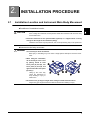
Installation Location and Instrument Main Body Movement
zConditions of installation location
CAUTION • Leave a space of 10 cm or more behind the instrument.
If the cooling fan is blocked, the temperature inside the instrument will rise and it may
cause malfunction.
• Install the instrument on the specified table (optional) or a support which is strong
enough for the weight of the instrument (52 kg).
Vibrations and noises may be produced, and normal processing may not be performed.
zInstrument main body movement
WARNING • Use a hand cart to move the instrument to a different location. At least two persons
are necessary to lift the instrument.
Back injury or stumbling may occur when a single person attempts to move the instrument.
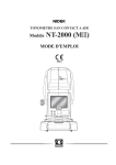
• When lifting the instrument,
do not lift it by its cover. Lift it
by placing hands at front
lower parts (A) and (B), rear
lower parts (C) and (D), and
right and left side lower parts
(E) and (F).
Lifting by the cover may
cause the instrument to
drop resulting in injury or
malfunction.
• Be careful not to get fingers caught when setting the lifted instrument down.
Fingers may get caught between the table and instrument resulting in injury.
3
2
INSTALLATION PROCEDURE: Unpacking
2.2
Unpacking
Unpack the shipping carton according to the following procedure.
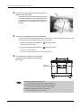
1
Hold the joint levers of the joints (4
units) and turn each of them to the
left.
Tape
The shipping carton is unlocked.
* Do not remove or cut the tape.
1
Υ
Υ
㸣
㸯
㸣
Shipping
carton
Joints (4 units)
Joint lever
2
Hold the shipping carton and lift it
up for removal.
2
Υ
Υ
㸣
㸣
3
Remove the accessory case,
upper pad, and upper right and left
packing support in order.
㸯
Upper pad
Shipping
carton
accessory
case
3
Upper right packing support
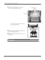
4
Place the main body in the installation position by two persons or
more.
Upper left packing support
4
Me 1200
main body
The weight of the main body is
approximately 52 kg.
See “2.1 Installation Location and
Instrument Main Body Movement”
(page 3).
4
Pallet base
INSTALLATION PROCEDURE: Accessory Check
2.3
Accessory Check
Confirm that the following are contained.
Pliable cup (red, green)
4 units each
Pliable cup for high base curve (red, green)
3 units each
Double-coated adhesive pad
1 set (100 sheets)
Touch pen
1 unit
Cup remover
1 unit
RMU/LMU calibration jig
1 unit
Hexagonal screwdriver (2.5 mm)
1 unit
Hexagonal wrench (3 mm)
1 unit
Hexagonal wrench (5 mm)
1 unit
Wrench (for attaching/removing grooving wheel)
1 unit
Wrench (for attaching/removing drill bit)
1 unit
Drill bit (o0.8, L6.5)
1 set (10 bits)
Drain hose adapter set
1 set
Feedwater hose
2 units
Tray
1 unit
Dressing stick for glass roughing wheel (WA80K)
1 unit (types PLB-G, PL-8, PLB-2R8)
Dressing stick for finishing wheel (WA320K)
1 unit
Compound kit for polishing wheel
1 set
Operator's manual
1 volume
Power cord
1 unit
2
5
INSTALLATION PROCEDURE: Spacer Removal
2.4
Spacer Removal
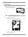
1
Insert the provided hexagonal wrench (5
mm) into the hole in the center of the left
side and unscrew a carriage fixing screw.
Accessory tray
Carriage fixing screw
• Store the removed screw in the accessory case.
It is used for securing the carriage when moving the instrument.
2
Remove the spacer in the processing unit.
1) Manually open the processing chamber door when it is closed.
2) Loosen two set screws on the spacer with the provided hexagonal screwdriver (2.5 mm).
Left LMU
(Surface feeler)
Right LMU
(Surface feeler)
Set screw
Spacer
Set screw
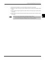
3) Push the bottom of the spacer to remove the spacer from the wheel shaft.
4) Push the lens chuck shaft up.
The lens chuck shaft moves slightly upward.
6
INSTALLATION PROCEDURE: Spacer Removal
5) Pull the top of the spacer to remove the spacer from the lens chuck shaft.
6) Remove the tape securing the safety beveling wheels and right and left LMU (surface
feeler).
7) After manually moving the right LMU (surface feeler) until all the way to the left, return it
to the right.
8) After manually moving the left LMU (surface feeler) until all the way to the right, return it
to the right.
2
• Be sure to move the surface feelers as described in Steps 7) and 8).
The right and left feelers may be sluggish just after the instrument is unpacked. If the surface feelers are not moved as described, the initialization may not be properly performed.
7
INSTALLATION PROCEDURE: Pipe Arrangement
2.5
Pipe Arrangement
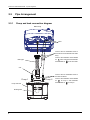
2.5.1
Pump and tank connection diagram
Main body
Inlets
Connect the two feedwater hoses to
the inlets on the underside of the main
body.
Drain pipe
1
Connect the feedwater hose labeled
as 1 to the rear inlet and feedwater
hose labeled as 2 to the front inlet.
2
Cuff
Connect the two feedwater hoses to
the tank as follows:
Pump 1
Pump and tank
Stocking filter
8
Pump 2
Connect the feedwater hose labeled
as
1
to Pump 1 and feedwater
hose labeled as
2
to Pump 2.
INSTALLATION PROCEDURE: Pipe Arrangement
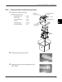
2.5.2
Pump and tank connection procedure
1
Remove the tank from the box.
[Contents of the tank box]
Extension cord
2 units
Drain pipe
1 unit
Feedwater hose
2 units
Cuff
1 unit
Stocking filter
20 units
Pump and tank
1 unit
Feedwater hoses
(2 units)
Extension
cords (2 units)
Cuff
Drain pipe
2
Stocking filter
(20 units)
Pump
and tank
2
Screw the drain pipe into the cuff.
Cuff
3
Drain pipe
Screw the other end of the drain pipe into the
hose adapter.
Hose adapter
9
INSTALLATION PROCEDURE: Pipe Arrangement
4
Connect the drain pipe to the aperture on the
bottom of the main body.
Ring
Push the hose adapter while aligning the hook
of the hose adapter with the indentations on the
underside aperture of the Me 1200 and turn the
light blue ring counterclockwise to secure the
adapter.
Hook
5
Connect the feedwater hose to the main body.
There are two inlets for feedwater hoses on the bottom of the main body. The front is the
connection for Pump 1 and the back is that for Pump 2.
1) Push the feedwater hose labeled as
1 into the rear inlet.
Push the hose until it clicks.
2) Push the feedwater hose labeled as 2 into the front inlet.
Push the hose until it clicks.
See “2.5.1 Pump and tank connection diagram” (page 8).
6
Put water into the tanks up to the guide
of water volume illustrated in the figure
to the right.
Guide of
water volume
• Do not put a plastic sheet in the tank.
The pump fill may be blocked and it may cause malfunction.
• Do not allow the water level to rise over the maximum line.
Failure to do so may cause malfunction or water leakage.
• Be sure to securely close the cover of the tank.
Foam may overflow if the cover is held up.
10
INSTALLATION PROCEDURE: Pipe Arrangement
7
Attach a new stocking filter and drain cover to
the tank.
1) Attach the stocking filter to the drain pipe
outlet of the tank.
Stocking filter
2
2) Put the drain cover in the drain pipe outlet of the tank.
Drain cover
Put the drain cover with the larger side facing
up.
Stocking filter
8
Plug the power cord of the pump into the main body.
1) Connect the power cord with label “1” the
extension code with label.
2) Route the extension code through the
hole on the top or rear of the table and
connect it to the outlet for Pump 1 in the
right side of the main body.
3) Connect the power cord with label “2”
with the extension code with label “2”.
4) Route the extension code through the
hole on the top or rear of the table and
connect it to the outlet for Pump 2 in the right side of the main body.
9
Pump
1
MAX.1A
Pump
2
MAX.1A
Put the tank back into the table.
10 Connect the feedwater hoses to the tank.
1) Push the feedwater hose labeled as
1 into the connection labeled as Pump 1.
Push the hose until it clicks.
2) Push the feedwater hose labeled as 2 into the connection labeled as Pump 2.
Push the hose until it clicks.
11
INSTALLATION PROCEDURE: Pipe Arrangement
11 Insert
the cuff attached to the drain
pipe into the drain pipe connector.
Feedwater hoses
Drain pipe
If the drain pipe length causes it to bend,
cut it to the proper length.
12 Connect the power cord to the outlet on the
rear side of the main body.
13 Connect
the plug of the power cord to a
wall outlet.
the main power plug to a grounded outlet.
CAUTION • Connect
Electric shock or fire may occur in the event of malfunction or power leakage.
12
INSTALLATION PROCEDURE: Pipe Arrangement
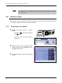
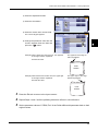
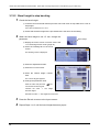
2.5.3
Checking the cleaning water and water curtain
1
Turn on the power into the Me 1200.
2
Press the
3
Press the Maintenance tab.
4
5
Menu
button.
Press the Cleaning button to the right of
Dressing.
2
3
4
Check the cleaning water and water curtain.
Pressing the Cleaning button displays the screen as below.
1) Press the
2) Press the
button and confirm that water flows from the cleaning water nozzle.
button and water flows from the water curtain nozzle.
Check connection of the feedwater hoses and pump and tank power codes when the cleaning
water and/or water curtain do not flow properly.
13
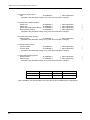
INSTALLATION PROCEDURE: Pipe Arrangement
3) Turn the flow control LEFT valve to
the left and right and check that the
water volume in the front side of the
processing chamber increases or
decreases.
4) Turn the flow control RIGHT valve to
the left and right and check that the
water volume in the rear side of the
processing chamber increases or
decreases.
Flow control LEFT valve
Flow control RIGHT valve
14
6
Press the
7
Press the Exit tab to return to the layout screen.
button to exit cleaning mode.
3.
3.1
CHECK AND ADJUSTMENT PROCEDURES
Check and Adjustment Procedure Flowchart
Load the circle 45 internal data and process a lens with the Two Point, Flat, None
(polish), and None (S.F.B.) settings.
No
Is the lens size
45.00 mm ±0.05 mm?
3
Perform LMU calibration.
Yes
Load the circle 45 internal data and process a lens with the Two Point, Flat, None
(polish), and Medium (S.F.B.) settings.
Is the safety-beveled edge
proper
Load the circle 45 internal data and process a lens with the Two Point, Flat, None
(polish), and None (S.F.B.) settings.
Yes
Yes
Is the lens size
45.00 mm ±0.05 mm?
No
No
Safety bevel adjustment
Size adjustment
Drilling confirmation shape processing
Hole diameter check
Hole depth check
Hole/slot reference, drill zero point, drill hole vertical position check
Front surface offset
Axis check and adjustment
Polish check and adjustment
Bevel check and adjustment
Groove position and depth check and adjustment
Finish
15
CHECK AND ADJUSTMENT PROCEDURES: Service mode
• Processing performances may be affected by transport and/or the installation conditions of
the instrument. Check and adjust the processing performances and complete the check list
(a copy of section 4).
3.2
Service mode
■ To perform check or adjustment procedure, enter service mode. There are General, Maintenance,
Grinding, Connection Counter, Error history settings.
3.2.1
Entering service mode
1
Display the menu screen in service
mode.
Press the Menu button while pressing
the
button.
1
The menu screen in service mode is
displayed.
1
2
While in service mode, the gray bar indicating service mode is displayed in the
left side of the screen.
3
3
16
Press the Exit tab to return to the layout
screen.
CHECK AND ADJUSTMENT PROCEDURES: Service mode
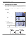
3.2.2
Loading the shape for adjustment
1
Display the menu screen in service mode.
See “3.2.1 Entering service mode” (page 16).
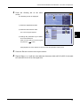
2
Press the Maintenance tab.
The Maintenance screen is displayed.
2
3
3
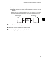
Load the desired internal shape data.
1) Press the desired button to the right
of "Shape for adjustment"
Circle 45
⇒ Press the Circle 45 button to the right
of “Shape for adjustment”.
1)
Square 45
⇒ Press the Square 45 button to the
right of “Shape for adjustment”.
Rectangle 50×25
⇒ Press the Rectangle 50×25 button to
the right of “Shape for adjustment”.
2) Loading the internal shape data automatically returns to the layout screen.
(The screen to the right is an example of
circle 45.)
17
CHECK AND ADJUSTMENT PROCEDURES: Size Check and Adjustment
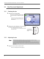
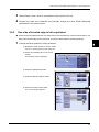
3.3
Size Check and Adjustment
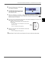
3.3.1
Checking the size
1
Load the circle 45 internal data.
For the circle 45 internal data, see “3.2.2
Loading the shape for adjustment” (page
17).
Process a lens with the settings as Two
Point, Flat, None (Polish), None (S.F.B.),
and Size 0.00.
2
Measure the outer diameter of the processed
lens with a caliper and check the size.
The outer diameter of the flat-edged lens is within
ø45.00mm ±0.05.
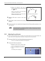
3.3.2
Outer diameter
Within ø45.00 mm
±0.05
Adjusting the size
• Calibrate surface measurement (LMU) once when the size is outside the range.
See “3.4 Surface Measurement (LMU) Calibration” (page 20).
• After the surface measurement (LMU) is calibrated, load the circle 45 internal data and
process a lens again. When the size is outside the range, adjust the size in the following
procedure.
1
Display the menu screen in service mode.
See “3.2.1 Entering service mode” (page 16).
18
CHECK AND ADJUSTMENT PROCEDURES: Size Check and Adjustment
2
Press the Grinding tab on the menu
screen.
The Grinding screen is displayed.
2
1) Press the Adjustment button.
2) Press the Size numeric field
The numeric keypad appears.
1)
2)
3
3) Change the parameter by the difference from 45.00 mm.
Enter the value with the numeric keypad
and press the
button.
Example)When the outer diameter is ø45.20, reduce the parameter value by 0.20.
3
4
Press the Exit tab to return to the layout screen.
Repeat Steps 1 to 3 until the outer diameter becomes within ø45.00 ±0.05 for beveled
lens and ø45.00 ±0.10 for flat-edged lens.
19
CHECK AND ADJUSTMENT PROCEDURES: Surface Measurement (LMU) Calibration
3.4
Surface Measurement (LMU) Calibration
■ Perform this calibration as necessary in size adjustment.
■ Calibrate surface measurement (LMU) using the provided RMU/LMU calibration jig.
CAUTION • Clean the surface feelers (LMUs) before calibration. Dirty feelers may cause
improper measurement.
• The RMU/LMU calibration jig easily comes loose from the lens adapter. As it
may fall in the processing chamber, be sure to hold the jig by hand to attach or
remove the jig.
1
Press the
Door
button to open the processing chamber door.
2
Press the
Menu
button.
The menu screen is displayed.
2
3
Press the Maintenance tab.
The Maintenance screen is displayed.
3
4
Attach the RMU/LMU calibration jig to the
lens adapter.
RMU
(periphery feeler)
1) Set the RMU/LMU calibration jig to
the lens adapter as shown to the
right.
2) Press the
the jig.
Right LMU
(surface feeler)
button to secure
Cup adapter
20
RMU/LMU calibration jig
CHECK AND ADJUSTMENT PROCEDURES: Surface Measurement (LMU) Calibration
5
6
7
8
Press the Surface meas. (LMU) button
to the right of Calibration.
The RMU/LMU calibration jig and right
and left surface feelers (LMUs) moves
and calibration starts.
5
When the calibration is complete, a chime sounds and “Calibration is finished” is displayed on the information bar. Hold the RMU/LMU calibration jig and press the
button to unlock it for removal.
Load the circle 45 internal data and process a lens with the settings as Two Point, Flat,
None (polish), None (S.F.B.), Size 0.00.
Measure the outer diameter of the processed lens to
check the size.
The outer diameter of the flat-edged len must be within
ø45.00 mm ±0.05.
Outer
diameter
See “3.3.1 Checking the size” (page 18).
9
Adjust the size when the outer diameter is other than
ø45.00mm ±0.05.
See “3.3.2 Adjusting the size” (page 18).
10 Repeat Steps 7 and 8 until the outer diameter of the lens is within the setting range.
21
3
CHECK AND ADJUSTMENT PROCEDURES: Safety Bevel Check and Adjustment
3.5
Safety Bevel Check and Adjustment
3.5.1
SFB setting
1
Display the menu screen in service mode.
See “3.2.1 Entering service mode” (page 16).
2
Press the Grinding tab on the menu
screen.
The Grinding screen is displayed.
3
2
Press the SFB setting button.
The SFB setting parameters are displayed.
3
4
Check the safety bevel amount of
Medium.
Press Medium.
•Rear, Bevel ⇒ 0.4
•Front, Bevel ⇒ 0.3, Exec
•Rear, Flat ⇒ 0.4
4
•Font, Flat ⇒0.3
Safety bevel amount
of the front surface
Beveling
22
Safety bevel amount
of the rear surface
Safety bevel amount
of the front surface
Safety bevel amount
of the rear surface
Flat (rimless) edging
CHECK AND ADJUSTMENT PROCEDURES: Safety Bevel Check and Adjustment
5
Load the circle 45 internal shape data.
1) For the circle 45 internal data, see
“3.2.2 Loading the shape for adjustment” (page 17).
2) Process a lens with the settings as
Two Point, Flat, None (polish),
Medium (S.F.B.), and Size 0.0.
3) Measure the front and rear safety
bevel amounts of the processed lens
and check them.
3
6
Change the parameter corresponding to
the wheel position until the safety bevel
amount becomes ±0.2 mm to the value
set in Step 4 after flat edging.
6
To increase the safety bevel amount,
increase the value.
To reduce the safety bevel amount,
decrease the value.
7
8
0.3 mm
0.4 mm
Check and adjust the bevel including the
bevel position check in the same manner.
Press the Exit tab to return to the layout
screen.
23
CHECK AND ADJUSTMENT PROCEDURES: Drilling Check and Adjustment
3.6
Drilling Check and Adjustment
3.6.1
Loading the drilling confirmation shape data
1
Display the menu screen in service mode.
See “3.2.1 Entering service mode” (page 16).
2
Press the Maintenance tab.
The Maintenance screen is displayed.
2
3
Load the drilling confirmation shape
data.
1) Press the desired drilling confirmation shape button.
•Confirmation (Hole)
•Hole diameter
•Hole position
•Front surface offset
•Hole depth
2) Loading the internal shape data
automatically returns to the layout
screen.
(The screen to the right is an example of
Confirmation (Hole).
24
1)
CHECK AND ADJUSTMENT PROCEDURES: Drilling Check and Adjustment
[Explanation of drilling confirmation shape data]
The drilling confirmation shape data contains the following drilling data.
3
Hole No.
Hole position 1
(X, Y)
Hole position 2
(X, Y)
Hole
diameter
Hole tilt
Hole depth
(1)
-18.50, -5.00
-
0.8
Auto
-
(2)
-18.50, 0.00
-
0.8
Auto
-
(3)
-18.50, +5.00
-
0.8
Auto
-
(4)
-9.60, +18.90
+9.60, +18.90
0.8
Angle 0.0
0.0 (drilled through)
(5)
-9.60, +21.00
-9.60, +18.90
0.8
X-Y 0.0, 0.5
0.0 (drilled through)
(6)
+9.60, +21.00
+9.60, +18.90
0.8
X-Y 0.0, 0.5
0.0 (drilled through)
(7)
+17.00, +17.00
-
0.8
Angle 0.0
0.0 (drilled through)
(8)
+17.00, +17.00
-
0.8
Angle 30.0
0.0 (drilled through)
(9)
+17.00, -17.00
-
2.0
Auto
0.0 (drilled through)
(10)
-4.00, -18.90
+4.00, -18.90
0.8
Angle 0.0
0.0 (drilled through)
(11)
-4.00, -21.00
-4.00, -18.90
0.8
X-Y 0.0, 0.5
0.0 (drilled through)
(12)
+4.00, -21.00
+4.00, -18.90
0.8
X-Y 0.0, 0.5
0.0 (drilled through)
25
CHECK AND ADJUSTMENT PROCEDURES: Drilling Check and Adjustment
1) Load the drilling confirmation shape data and process a lens.
Use the standard o0.8 drill bit.
2) Check the hole diameter.
It is normal when the diameter of hole (9) becomes 2.0 ±0.1 mm.
3) Check the hole depth.
Check the depths of holes (1) to (3). It is normal when hole (3) is drilled and hole (2) is slightly
made on the lens surface.
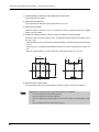
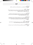
4) Check the hole/slot reference, drill zero point, and drill hole vertical position.
Check the hole/slot reference, drill zero point, and drill hole Vertical position at the holes (4) to (6)
and (10) to (12).
• Hole/slot reference: It is normal when the difference between A and B in the figure below is within
0.1 mm.
• Drill zero point: It is normal when the difference between C and D in the figure below is within 0.1
mm.
• Drill hole vertical position: It is normal when the L in the figure below is 37.0 ±0.1 mm.
19
A
C
D
B
L
5) Check the front surface offset.
It is normal when holes (7) and (8) are drilled in the same position on the lens front surface.
• Adjustment is necessary when the specified values are not obtained.
See “3.6.2 Adjusting the hole diameter” (page 27).
See “3.6.3 Adjusting the hole depth” (page 28).
See “3.6.4 Adjusting the hole/slot reference, drill zero point, and drill hole vertical position” (page
29).
See “3.6.5 Adjusting the front surface offset” (page 31).
26
CHECK AND ADJUSTMENT PROCEDURES: Drilling Check and Adjustment
3.6.2
Adjusting the hole diameter
■ Adjust the hole diameter in the following procedure when the hole diameter is not ø2.0 mm ±0.1
mm after the drilling confirmation shape is checked.
1
Display the menu screen in service mode.
See “3.2.1 Entering service mode” (page 16).
2
Press the Grinding tab on the menu
screen.
The Grinding screen is displayed.
2
3
1) Press the Adjustment button.
2) Press the Hole button.
1)
2)
3
Adjust the hole diameter.
Press the "Diameter
numeric field.
adjustment"
Change the parameter value with the
numeric keypad. Enter the value and
press the
button.
3
When the ø2.0 straight pin does not pass through the hole,
increase the hole diameter.
When the ø2.0 straight pin is loose around the
hole, reduce the hole diameter.
4
5
Press the Exit tab to return to the layout screen.
Repeat processing the lens with drilling confirmation shape data and Steps 1 to 4 until the
hole diameter becomes proper.
27
CHECK AND ADJUSTMENT PROCEDURES: Drilling Check and Adjustment
3.6.3
Adjusting the hole depth
■ Adjust the hole depth in the following procedure when the hole depth is outside the setting range
after the drilling confirmation shape is checked.
1
Display the menu screen in service mode.
See “3.2.1 Entering service mode” (page 16).
2
Press the Grinding tab on the menu
screen.
The Grinding screen is displayed.
2
1) Press the Adjustment button.
2) Press the Hole button.
1)
2)
3
Adjust the hole depth.
Press the "Depth adjustment" numeric
field.
Change the parameter value with the
numeric keypad. Enter the value and
press the
button.
When holes (1) to (3) are all drilled,
the reference value of Depth adjustment is -0.2 mm.
When holes (1) to (3) are not drilled at all,
the reference value of Depth adjustment is 0.2 mm.
4
5
28
Press the Exit tab to return to the layout screen.
Repeat processing the lens with drilling confirmation shape data and Steps 1 to 4 until the
hole depth becomes proper.
3
CHECK AND ADJUSTMENT PROCEDURES: Drilling Check and Adjustment
3.6.4
Adjusting the hole/slot reference, drill zero point, and drill hole vertical position
■ Adjust the hole/slot reference, drill zero point, and hole vertical position in the following procedure
when these are outside the setting range after the drilling confirmation shape is checked.
1
Display the menu screen in service mode.
See “3.2.1 Entering service mode” (page 16).
2
Press the Grinding tab on the menu
screen.
The Grinding screen is displayed.
2
3
1) Press the Adjustment button.
2) Press the Hole button.
1)
2)
zAdjusting the hole/slot reference
When the difference between A and B is
0.1 mm or more, press the "Hole/slot reference" numeric field.
Change the parameter value with the
numeric keypad. Enter the value and
press the
button.
• A < B Increase the adjustment value.
• A > B Decrease the adjustment value.
29
CHECK AND ADJUSTMENT PROCEDURES: Drilling Check and Adjustment
zAdjusting the Drill zero point
When the difference between C and D is 0.1 mm or more, press the "Drill zero point"
numeric field.
Change the parameter value with the numeric keypad. Enter the value and press the
button.
When D > C and the difference between C and D is 1.0 mm,
set the parameter to 0.5.
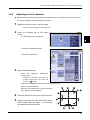
zAdjusting the drill hole vertical position
Press the "Drill hole vertical position" numeric field when the L length is not 37.0 mm ±0.1
mm.
Change the parameter value with the numeric keypad. Enter the value and press the
button.
For L = 37.2 mm,
set the parameter to -0.1.
19
A
C
D
B
L
3
4
30
Press the Exit tab to return to the layout screen.
Repeat processing the lens with drilling confirmation shape data and Steps 1 to 4 until
each value becomes proper.
CHECK AND ADJUSTMENT PROCEDURES: Drilling Check and Adjustment
3.6.5
Adjusting the front surface offset
■ Adjust the front surface offset in the following procedure when the front surface offset is outside
the setting range after the drilling confirmation shape is checked.
1
Display the menu screen in service mode.
See “3.2.1 Entering service mode” (page 16).
2
Press the Grinding tab on the menu
screen.
The Grinding screen is displayed.
2
3
1) Press the Adjustment button.
2) Press the Hole button.
1)
2)
3
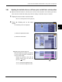
Adjust the front surface offset.
1) Press the "Front surface offset"
numeric field when the hole positions
of (7) and (8) are not aligned.
The numeric keypad appears.
2) Change the parameter value with the
numeric keypad. Enter the value and
press the
button.
3
When the 30º tilt hole is drilled on the 0º hole,
decrease the parameter value.
When the 30º tilt hole is drilled under the 0º hole,
increase the parameter value.
31
CHECK AND ADJUSTMENT PROCEDURES: Axis Adjustment
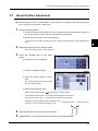
3.7
Axis Adjustment
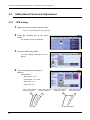
3.7.1
Adjusting the axis shift
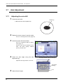
1
Check the axis shift.
Pliable cup
1) Block the lens with a pliable cup
2
Display the menu screen in service mode.
See “3.2.1 Entering service mode” (page 16).
3
Load the square 45 internal data
See “3.2.2 Loading the shape for adjustment” (page 17).
Process a lens with the settings as Two
Point, Flat None (polish), Medium
(S.F.B.), and Size 0.00.
4
Check the axis angle using the axis
adjustment jig.
The edged surface rises up to the right.
Adjust the axis angle when it is not ±0.5º.
Axis adjustment jig
5
32
Lens
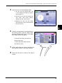
Adjust the axis angle.
CHECK AND ADJUSTMENT PROCEDURES: Axis Adjustment
1) Press the
Menu
button on the lay-
out screen while pressing the
button.
1
The menu screen in service mode is
displayed.
2) Press the Grinding tab on the menu
screen.
The Grinding screen is displayed.
2)
3
3) Press the Adjustment button.
4) Press the Axis numeric field.
The numeric keypad appears.
3)
4)
5) Change the parameter value with the
numeric keypad. Enter the value and
press the
button.
Change the parameter value by the shifted axis angle.
When the lens edge is shifted in the upper right direction when viewed from the rear surface,
increase the value.
Example) When lens edge is shifted 1º in the upper right direction, increase the parameter value by
1.00.
6
Press the Exit tab to return to the layout screen.
7
Repeat Steps 1 to 6 until the shifted axis angle becomes ±0.5º.
33
CHECK AND ADJUSTMENT PROCEDURES: Axis Adjustment
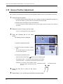
3.7.2
Safety bevel amount is not consistent
■ When the safety bevel amount of the processed lens is not consistent in circumference after the
shifted axis angle is adjusted “3.7.1 Adjusting the axis shift” (page 32), the safety bevel axis may
be shifted. Adjust the safety bevel axis angle.
1
When the safety bevel amount is different between the upper right and upper left of the
processed lens, change the "Rear, Flat" or "Front, Flat" parameter to adjust the safety
bevel axis angle.
1) Display the menu screen in service mode.
See “3.2.1 Entering service mode” (page 16).
2) Press the Grinding tab on the menu
screen.
The Grinding screen is displayed.
2)
3) Press the SFB setting button
The SFB setting parameters are displayed.
3)
2
Set the safety bevel amount on the SFB
axis parameter.
1) Press the SFB axis button.
2) Press the "Rear, Flat" numeric field.
2)
The numeric keypad appears.
3) Change the parameter value with the
numeric keypad. Enter the value and
press the
button.
1)
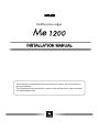
When the safety bevel amount of the upper right is larger when viewed from the rear surface,
increase the value. When the safety bevel amount of the upper left is larger, decrease the value.
The safety bevel amount of the
upper right is larger.
㸫
34
The safety bevel amount of the
upper left is larger.
Rear
surface
㸩
CHECK AND ADJUSTMENT PROCEDURES: Axis Adjustment
4) Press the "Front, Flat" numeric field.
Pressing the numeric field displays the numeric keypad.
5) Change the parameter value with the numeric keypad. Enter the value and press the
button.
When the safety bevel amount of the upper right is larger when viewed from the front surface,
increase the value. When the safety bevel amount of the upper left is larger, decrease the value.
The safety bevel amount of the
upper right is larger
㸩
The safety bevel amount of the
upper left is larger
Front
surface
㸫
3
Press the Exit tab to return to the layout screen.
4
Repeat Steps 1 to 3 until the safety bevel amount is proper.
5
Perform beveling. Change "Rear, Bevel", "Front, Bevel" in the same manner.
3
35
CHECK AND ADJUSTMENT PROCEDURES: Polishing Adjustment
3.8
Polishing Adjustment
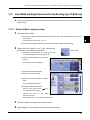
3.8.1
Lens edge is left unpolished or burnt
■ Check the bevel polished surface of a plastic lens processed with the circle 45 internal data. If the
lens edge is left unpolished or burnt, change the Polish differential parameter.
1
Change the Polish differential parameter.
1) Display the menu screen in service mode.
See “3.2.1 Entering service mode” (page 16).
2) Press the Grinding tab on the menu
screen.
The Grinding screen is displayed.
2)
3) Press the Adjustment button.
4) Press the Size button.
3)
4)
5) Press the "Polish differential" button.
6) Press the "CR39, Bevel" numeric
field.
The numeric keypad appears.
7) Change the parameter value with the
numeric keypad. Enter the value and
press the
button.
When the lens edge is left unpolished,
increase the Polish differential parameter by 0.05.
When the lens edge is burnt,
decrease the parameter by 0.05.
2
36
Press the Exit tab to return to the layout screen.
5)
6)
CHECK AND ADJUSTMENT PROCEDURES: Polishing Adjustment
3
4
3.8.2
Repeat Steps 1 and 2 until no unpolished or burnt portions are left.
Process the other lens materials and precisely change the other Polish differential
parameters in the same manner.
One side of beveled edge is left unpolished
■ Check the bevel polished surface of a plastic lens processed with the circle 45 internal data. If one
side of the beveled edge is left unpolished, change the Bevel position (Polish) parameter.
1
Change the Bevel position (Polish) parameter.
3
1) Display the menu screen in service mode.
See “3.2.1 Entering service mode” (page 16).
2) Press the Grinding tab on the menu
screen.
The Grinding screen is displayed.
2)
3) Press the Adjustment button.
4) Press the "Bevel position" button.
3)
4)
5) Press the Polish numeric field.
The numeric keypad appears.
5)
37
CHECK AND ADJUSTMENT PROCEDURES: Polishing Adjustment
6) Change the parameter value with the
numeric keypad. Enter the value and press
the
button.
Front surface remains unpolished.
When the front surface of the bevel remains
unpolished, increase the value.
When the rear surface of the bevel remains
unpolished, decrease the value.
2
3
4
Rear surface remains unpolished.
Press the Exit tab to return to the layout
screen.
Repeat Steps 1 and 2 until the bevel is properly
polished.
Process the other lens materials and change the other Bevel position parameter in the
same manner.
• When the bevel position is changed, the polish bevel position is also moved. As long as the
polish bevel position is properly adjusted, it does not need to be adjusted again even if the
bevel position is changed afterward.
3.8.3
Adjusting the polish axis
■ Check the bevel polished surface of a plastic lens processed with the circle 45 internal data. If the
right or left of the lens edge remains unpolished, change the Polish axis parameter.
1
Decrease "CR39, Flat" of the Polish differential parameter by 0.2.
See “3.8.1 Lens edge is left unpolished or burnt” (page 36).
2
Change the Polish axis parameter.
1) Display the menu screen in service mode.
See “3.2.1 Entering service mode” (page 16).
2) Press the Grinding tab on the menu
screen.
The Grinding screen is displayed.
38
2)
CHECK AND ADJUSTMENT PROCEDURES: Polishing Adjustment
3) Press the Adjustment button.
4) Press the Axis button.
3)
4)
5) Press the "Polish axis" numeric field.
The numeric keypad appears.
6) Change the parameter value with the
numeric keypad. Enter the value and
press the
button.
Example) When viewed from the lens front, the upper left
of the edge remains unpolished.
5)
3
The upper left of the edge remains unpolished.
increase the value.
Front
surface
Example) When viewed from the lens front, the upper right
of the edge remains unpolished.
The upper right of the edge
remains unpolished.
decrease the value.
Front
surface
3
Press the Exit tab to return to the layout screen.
4
Repeat Steps 1 and 2 until the polishing becomes uniform in circumference.
5
Set the parameter values of "CR39, Flat" of the Polish differential parameter back to their
original values.
39
CHECK AND ADJUSTMENT PROCEDURES: Polishing Adjustment
3.8.4
Adjusting the polish size
■ Check the polished surface of a lens processed with the circle 45 internal data. If the outer diame-
ter is not within ø45.00 ±0.10 mm, change the Polish size parameter.
1
Check the Polish size parameter.
1) Load the circle 45 internal data and bevel-polish and flat-polish a lens.
2) Measure the outer diameter of the processed lens.
When the outer diameter is not within ø45.00 ±0.10 mm, change the Polish size parameter.
See “3.2.2 Loading the shape for adjustment” (page 17).
See “3.3 Size Check and Adjustment” (page 18).
Outer
diameter
2
Outer
diameter
Adjust the polish size.
1) Display the menu screen in service mode.
See “3.2.1 Entering service mode” (page 16).
2) Press the Grinding tab on the menu
screen.
The Grinding screen is displayed.
2)
3) Press the Adjustment button.
4) Press the Size button.
3)
40
4)
CHECK AND ADJUSTMENT PROCEDURES: Polishing Adjustment
5) Press the "Polish size" button.
6) Press the numeric field of the desired
parameter item.
The numeric keypad appears.
5)
7) Change the parameter value with the
numeric keypad. Enter the value and
press the
button.
6)
3
{Parameter items
Select parameter items according to the lens material and processing method.
zWith the lens material set to "CR39", the bevel-polished lens size is not correct.
⇒ CR39, Bevel
zWith the lens material set to "CR39", the flat-polished lens size is not correct.
⇒ CR39, Flat
zWith the lens material set to "Hi-index", the bevel-polished lens size is not correct.
⇒ Hi-index, Bevel
zWith the lens material set to "Hi-index", the flat-polished lens size is not correct.
⇒ Hi-index, Flat
zWith the lens material set to "Polyca." or "Acrylic", the bevel-polished lens size is not correct.
⇒ Polyca./Acrylic, Bevel
zWith the lens material set to "Polyca." or "Acrylic", the flat-polished lens size is not correct.
⇒ Polyca./Acrylic, Flat
zWith the lens material set to "Trivex", the bevel-polished lens size is not correct.
⇒ Trivex, Bevel
zWith the lens material set to "Trivex", the flat-polished lens size is not correct.
⇒ Trivex, Bevel
zWith the lens material set to "Urethane", the bevel-polished lens size is not correct.
⇒ Urethane, Bevel
zWith the lens material set to "Urethane", the flat-polished lens size is not correct.
⇒ Urethane, Flat
41
CHECK AND ADJUSTMENT PROCEDURES: Polishing Adjustment
8) Change the parameter by the difference between 45.00 mm and the outer diameter.
Change the parameter value with the numeric keypad. Enter the value and press the
Example) When the outer diameter is ø45.15, decrease the parameter value by 0.15.
42
3
Press the Exit tab to return to the layout screen.
4
Repeat Steps 1 to 3 until the outer diameter becomes ø45.10 ±0.10 mm.
button.
CHECK AND ADJUSTMENT PROCEDURES: Bevel Position Adjustment
3.9
Bevel Position Adjustment
■ The bevel position can be moved toward the front or back by changing the bevel position parame-
ter for a lens being processed in Auto mode.
1
Check the bevel position.
1) Load the circle 45 internal data (see “3.2.2 Loading the shape for adjustment” (page 17))
and in Auto mode, process a lens of a thickness commonly used.
2) Check the bevel position of the processed lens.
To move the bevel position toward front or back, adjust the bevel position in the following procedure.
2
Display the menu screen in service mode.
See“3.2.1 Entering service mode” (page 16).
3
Press the Grinding tab on the menu
screen.
The Grinding screen is displayed.
3
1) Press the Adjustment button.
2) Press the "Bevel position" numeric
field.
1)
The numeric field turns orange and the
numeric keypad appears.
2)
3) Change the parameter value.
Enter the value and press the
button with the numeric keypad.
Decrease the numeric value. ⇒ The bevel moves toward the front surface.
Increase the numeric value. ⇒ The bevel moves toward the rear surface.
Example) To move the bevel position toward the rear
Decrease the value.
surface by 0.5 mm, decrease the value by 0.50.
4
Press the Exit tab to return to the layout screen.
5
Repeat Steps 1 to 4 until the bevel is produced in the proper position.
Increase the value.
43
3
CHECK AND ADJUSTMENT PROCEDURES: Groove Position Adjustment
3.10 Groove Position Adjustment
■ The auto-processed groove position can be adjusted toward the front or rear surface of the lens.
1
Check the groove position.
1) Load the circle 45 internal data (see “3.2.2 Loading the shape for adjustment” (page 17))
and in Auto mode, process a lens of a thickness commonly used.
2) Check the groove position of the processed lens.
To move the groove position toward the front or back, adjust the groove position in the following
procedure.
2
Display the menu screen in service mode.
See “3.2.1 Entering service mode” (page 16).
3
Press the Grinding tab on the menu
screen.
The Grinding screen is displayed.
3
1) Press the Adjustment button.
2) Press the "Groove position" numeric
field.
1)
The numeric field turns orange and the
numeric keypad appears.
2)
3) Change the parameter value.
Enter the value and press the
button with the numeric keypad.
Decrease the value. ⇒ The groove moves toward the front surface.
Increase the value. ⇒ The groove moves toward the rear surface.
Example) To move the groove position toward
the front surface, decrease the value
by 0.50.
4
5
44
Decrease the value.
Press the Exit tab to return to the layout
screen.
Repeat Steps 1 to 4 until the groove position becomes proper.
Increase the value.
CHECK AND ADJUSTMENT PROCEDURES: Groove Depth Adjustment
3.11 Groove Depth Adjustment
■ When the groove depth differs from a specified value, adjust the groove depth.
1
Check the groove depth.
1) Load the circle 45 internal shape data (see “3.2.2 Loading the shape for adjustment”
(page 17)) and process a lens with the groove depth 0.0 mm in auto grooving mode.
Use a CR-39 lens of -3 to -5 D.
2) Check that the groove is slightly made (the depth is within 0.10 mm) on the processed
lens.
2
3
Display the menu screen in service mode.
See “3.2.1 Entering service mode” (page 16).
3
Press the Grinding tab on the menu
screen.
The Grinding screen is displayed.
3
1) Press the Adjustment button.
2) Press the "Groove position" button.
1)
2)
3) Press the Depth numeric field in the
Groove position parameter.
The numeric field turns orange and the
numeric keypad appears.
4) Change the parameter value.
Enter a value with the numeric keypad
and press the
button.
3)
Decrease the numeric value. ⇒ The groove becomes shallower.
Increase the numeric value. ⇒ The groove becomes deeper.
45
CHECK AND ADJUSTMENT PROCEDURES: Groove Depth Adjustment
Example)To deepen the groove depth by 0.5 mm,
increase the value by 0.50.
Decrease the value.
Increase the value.
46
4
Press the Exit tab to return to the layout screen.
5
Repeat steps 1 to 4 until the groove depth becomes proper.
CHECK AND ADJUSTMENT PROCEDURES: Bevel Width and Height Adjustment for Step Beveling (Type
3.12
Bevel Width and Height Adjustment for Step Beveling (Type PLB-8S only)
■ Change the parameters when the bevel width and height are different from the specified value in
step beveling.
3.12.1 Bevel width in step beveling
1
Check the bevel width.
1) Load the circle 45 internal data and process a lens with 2 mm in step width and 1.5 mm in
step height.
3
Process a lens of CR39 and -4 to -5 D.
2) Check that the bevel width of the processed lens is the same as the setting.
2
When the bevel width is not 2 mm, change the
parameter in the following procedure.
Bevel width
1) Display the menu screen in service mode. See
“3.2.1 Entering service mode” (page 16).
2) Press the Grinding tab on the menu
screen.
The Grinding screen is displayed.
2)
3) Press the Adjustment button.
4) Press the Hi-curve button.
5) Press the "Wheel position" numeric
field.
3)
The numeric keypad appears.
4)
6) Change the parameter value.
Enter the value and press the
ton with the numeric keypad.
Increase the value.
becomes narrower.
⇒
The
but-
5)
width
Decrease the value. ⇒ The width becomes wider.
3
Press the Exit tab to return to the layout screen.
4
Repeat Steps 1 to 3 until the bevel width becomes proper.
47
CHECK AND ADJUSTMENT PROCEDURES: Bevel Width and Height Adjustment for Step Beveling (Type PLB-8S only)
3.12.2 Bevel height in step beveling
1
Check the bevel height.
1) Load the circle 45 internal data and process a lens with 2 mm in step width and 1.5 mm in
step height.
Use a lens of CR39 and -4 to -5 D.
2) Check that the bevel height of the processed lens is the same as the setting.
2
When the bevel height is not 1.5 mm, change the
parameter.
Bevel height
1) Display the menu screen in service mode. See
“3.2.1 Entering service mode” (page 16)
2) Press the Grinding tab on the menu
screen.
The Grinding screen is displayed.
2)
3) Press the Adjustment button.
4) Press the Hi-curve button.
5) Press the "Wheel height" numeric
field.
3)
The numeric keypad appears.
4)
6) Change the parameter value.
Enter the value and press the
ton with the numeric keypad.
Increase the value.
becomes higher.
⇒
The
butheight
Decease the value. ⇒ The height becomes lower.
48
3
Press the Exit tab to return to the layout screen.
4
Repeat Steps 1 to 3 until the bevel height becomes proper.
5)
CHECK AND ADJUSTMENT PROCEDURES: Clock Check
3.13 Clock Check
Check the date and time of the internal clock.
Change the time and date referring to “Date and time” in the operator's manual.
3
49
CHECK AND ADJUSTMENT PROCEDURES: Clock Check
50
4.
4.1
CHECK LIST
Me 1200 Installation Work Check List
After the instrument is installed, record the results. Check the boxes for checked items.
Fill in the blanks (
) with parameter values.
Is the installation place proper?
Are the connections of Pump 1 and Pump 2 proper?
Check the drain condition in cleaning mode.
Is the date and time setting proper?
Is the processed size proper?
Size
At installation (
) After adjustment (
)
Complete if size adjustment of any other items has been made.
Is the safety bevel amount proper?
Medium (Rear, Flat)
At installation (
) After adjustment (
Medium (Front, Flat)
At installation (
) After adjustment (
Medium (Rear, Bevel)
At installation (
) After adjustment (
Medium (Front, Bevel)
At installation (
) After adjustment (
Complete if the parameter setting of any other items has been changed.
)
)
)
)
Is the safety bevel axis proper?
Rear, Flat
At installation (
) After adjustment (
Front, Rear
At installation (
) After adjustment (
Rear, Bevel
At installation (
) After adjustment (
Front, Bevel
At installation (
) After adjustment (
Complete if the parameter setting of any other items has been changed.
)
)
)
)
Is the drilling proper?
Hole diameter
At installation (
) After adjustment (
Hole depth
At installation (
) After adjustment (
Hole/slot reference
At installation (
) After adjustment (
Drill zero point
At installation (
) After adjustment (
Drill hole vertical position
At installation (
) After adjustment (
Front surface offset
At installation (
) After adjustment (
Complete if the parameter setting of any other items has been changed.
)
)
)
)
)
)
51
4
CHECK LIST: Me 1200 Installation Work Check List
Is the axis angle proper?
Axis
At installation (
) After adjustment (
Complete if the parameter setting of any other items has been changed.
)
Is the polish condition proper?
Polish size
At installation (
) After adjustment (
Polish axis
At installation (
) After adjustment (
Polish differential (CR39, Bevel) At installation (
) After adjustment (
Bevel position (Polish)
At installation (
) After adjustment (
Complete if the parameter setting of any other items has been changed.
)
)
)
)
Is the bevel position proper?
Bevel position
At installation (
) After adjustment (
Complete if the parameter setting of any other items has been changed.
)
Is the grooving proper?
Groove position
At installation (
) After adjustment (
Groove depth
At installation (
) After adjustment (
Complete if the parameter setting of any other items has been changed.
)
)
Is the step beveling proper?
Wheel position
At installation (
) After adjustment (
Wheel height
At installation (
) After adjustment (
Complete if the parameter setting of any other items has been changed.
)
)
Product name
Type
S/N
Ver.
Installation date
Installer
* After installation, the representative must send this list to the NIDEK Service Department.
52