Transcript
User's Manual
(Hardware)
Mitsubishi Programmable
Controller
Type
QJ61CL12-U-HW-JE
Type code
13JP01
IB(NA)-0800232-E(1009)MEE
© 2002 MITSUBISHI ELECTRIC CORPORATION
zSAFETY PRECAUTIONSz
(Always read these instructions before using this equipment.)
Before using this product, please read this manual and the relevant manuals introduced in this
manual carefully and pay full attention to safety to handle the product correctly.
These instructions apply only to Mitsubishi equipment. Refer to the user’s manual of the CPU
module to use for a description of the programmable controller system safety instructions.
In this manual, the safety instructions are ranked as " WARNING " and " CAUTION".
(2) The PRODUCT has been designed and manufactured for the purpose of being used in general
industries.
MITSUBISHI SHALL HAVE NO RESPONSIBILITY OR LIABILITY (INCLUDING, BUT NOT
LIMITED TO ANY AND ALL RESPONSIBILITY OR LIABILITY BASED ON CONTRACT,
WARRANTY, TORT, PRODUCT LIABILITY) FOR ANY INJURY OR DEATH TO PERSONS OR
LOSS OR DAMAGE TO PROPERTY CAUSED BY the PRODUCT THAT ARE OPERATED OR
USED IN APPLICATION NOT INTENDED OR EXCLUDED BY INSTRUCTIONS,
PRECAUTIONS, OR WARNING CONTAINED IN MITSUBISHI'S USER, INSTRUCTION
AND/OR SAFETY MANUALS, TECHNICAL BULLETINS AND GUIDELINES FOR the PRODUCT.
("Prohibited Application")
Prohibited Applications include, but not limited to, the use of the PRODUCT in;
• Nuclear Power Plants and any other power plants operated by Power companies, and/or any
other cases in which the public could be affected if any problem or fault occurs in the PRODUCT.
• Railway companies or Public service purposes, and/or any other cases in which establishment
of a special quality assurance system is required by the Purchaser or End User.
• Aircraft or Aerospace, Medical applications, Train equipment, transport equipment such as
Elevator and Escalator, Incineration and Fuel devices, Vehicles, Manned transportation,
Equipment for Recreation and Amusement, and Safety devices, handling of Nuclear or
Hazardous Materials or Chemicals, Mining and Drilling, and/or other applications where there is
a significant risk of injury to the public or property.
Notwithstanding the above, restrictions Mitsubishi may in its sole discretion, authorize use of the
PRODUCT in one or more of the Prohibited Applications, provided that the usage of the PRODUCT
is limited only for the specific applications agreed to by Mitsubishi and provided further that no
special quality assurance or fail-safe, redundant or other safety features which exceed the general
specifications of the PRODUCTs are required. For details, please contact the Mitsubishi
representative in your region.
ABOUT MANUAL
The following manual is also related to this product.
In necessary, order it by quoting the details in the table below.
Related Manual
WARNING
CAUTION
Indicates that incorrect handling may cause hazardous
conditions, resulting in death or severe injury.
Indicates that incorrect handling may cause hazardous
conditions, resulting in medium or slight personal injury or
physical damage.
Note that the
CAUTION level may lead to a serious consequence according to the
circumstances.
Always follow the instructions of both levels because they are important to personal safety.
Please save this manual to make it accessible when required and always forward it to the end
user.
Manual number
(Model code)
SH-080351E
(13JR62)
Manual name
CC-Link/LT Master Module User's Manual
Conformation to the EMC Directive and Low Voltage Instruction
(1) For programmable controller system
To configure a system meeting the requirements of the EMC and Low Voltage Directives
when incorporating the Mitsubishi programmable controller (EMC and Low Voltage
Directives compliant) into other machinery or equipment, refer to Chapter 9 "EMC AND
LOW VOLTAGE DIRECTIVES" of the QCPU User's Manual (Hardware Design,
Maintenance and Inspection).
The CE mark, indicating compliance with the EMC and Low Voltage Directives, is
printed on the rating plate of the programmable controller.
(2) For the product
[Design Precautions]
CAUTION
z Do not bunch the control wires or communication cables with the main circuit or power
wires, or install them close to each other.
They should be installed 100mm (3.9inch) or more from each other.
Not doing so could result in noise that would cause erroneous operation.
[Installation Precautions]
CAUTION
z Use the programmable controller in an environment that meets the general specifications
contained in the CPU user's manual to use.
Using this programmable controller in an environment outside the range of the general
specifications could result in electric shock, fire, erroneous operation, and damage to or
deterioration of the product.
z While pressing the installation lever located at the bottom of module, insert the module
fixing tab into the fixing hole in the base unit until it stops. Then, securely mount the
module with the fixing hole as a supporting point.
Incorrect loading of the module can cause a malfunction, failure or drop.
When using the programmable controller in the environment of much vibration, tighten the
module with a screw.
Tighten the screw in the specified torque range.
Undertightening can cause a drop, short circuit or malfunction.
Overtightening can cause a drop, short circuit or malfunction due to damage to the screw
or module.
z Completely turn off the externally supplied power used in the system before mounting or
removing the module. Not doing so could result in damage to the product.
z Do not directly touch the module's conductive parts or electronic components.
Touching the conductive parts could cause an operation failure or give damage to the module.
[Wiring Precautions]
WARNING
z Shut off the external power supply for the system in all phases before wiring. Failure to do
so may result in electric shock or damage to the product.
For the compliance of this product with the EMC and Low Voltage Directives, refer to
Chapter 9 "EMC AND LOW VOLTAGE DIRECTIVES" of the QCPU User's Manual
(Hardware Design, Maintenance and Inspection).
1. Overview
This manual describes the specifications, names of each part and the settings, etc., for the
QJ61CL12 CC-Link/LT master module (hereinafter QJ61CL12) used in combination with the
MELSEC-Q Series programmable controller CPU.
2. Specifications
2.1 Performance specifications
The performance specifications of the QJ61CL12 are shown below.
Refer to the user's manual of the CPU module in use for the general specifications of the
QJ61CL12.
Item
Maximum link points
(When the same I/O address is used)
Link points per station
(When the same I/O address is used)
Number of
points
When 32
stations are 2.5Mbps
Control
connected
625kbps
specifications
Link
156kbps
scan
Number of
time
points
When 64
stations are 2.5Mbps
connected 625kbps
156kbps
Transmission rate
Communication method
Communication path
Error control system
Communication Maximum number of modules
specifications Remote station No.
Installation position of master station
CAUTION
z Be sure there are no foreign substances such as sawdust or wiring debris inside the
module. Such debris could cause fires, damage, or erroneous operation.
z The module has an ingress prevention label on its top to prevent foreign matter, such as
wire offcuts, from entering the module during wiring.
Do not peel this label during wiring.
Before starting system operation, be sure to peel this label because of heat dissipation.
z For the CC-Link/LT, use the cables specified by the CC-Link Partner Association.
The performance of the CC-Link/LT cannot be assured if any other cables than the
specified are used.
Also, observe the network wiring specifications given in Chapter 2.
Normal data communication is not guaranteed if the wiring is not conducted according to
the specifications.
z Place the communication cables or power cables for the module in a duct or to fasten
them with clamps.
If not, the dangling condition, shift or inadvertent pulling of the cables may lead to damage
to the module or cables, or a malfunction due to faulty cable connection.
z When disconnecting a communication cable or power cable from the module, do not hold
and pull the cable portion by hand.
For the cable with a connector, hold the connector connected to the module with a hand
and pull it out.
For the cable connected to a terminal block, loosen the screws on the terminal block and
disconnect the cable.
Pulling the cable with it connected to the module may result in malfunctions or damage to
the module and/or cables.
RAS-oriented functions
Connection cable *1
I/O occupied points *2
5VDC internal current consumption
Voltage
24VDC power supply
Current consumption
*3
Current on startup
Weight
4-point mode
256 points
(512 points)
4 points
(8 points)
Specifications
8-point mode
512 points
(1024 points)
8 points
(16 points)
16-point mode
1024 points
(2048 points)
16 points
(32 points)
128 points
256 points
512 points
0.7ms
2.2ms
8.0ms
0.8ms
2.7ms
10.0ms
1.0ms
3.8ms
14.1ms
256 points
512 points
1024 points
1.5ms
2.0ms
5.4ms
7.4ms
20.0ms
27.8ms
2.5Mbps/625kbps/156kbps
BITR (Broadcastpolling+Interval Timed Response)
T-branch type
CRC
64
1 to 64
End of trunk line
Network diagnosis, internal loopback diagnosis, station
detach function, automatic return function
Dedicated flat cable (0.75mm2 4) *5, VCTF cable *4,
High flexible cable *5
16,32,48,64,128,256,512,1024 point
(I/O assignment: intelligent)
0.13A
20.4 to 28.8V DC
0.028A
0.070A
0.09kg
Type
Vinyl cabtyre,
Round cord
VCTF cable specifications (Extract from JIS C 3306)
Conductor
No. of
Nominal
Composition
cores cross-sectional No. of wires/wire Outside
diameter
area
diameter
4
0.75mm2
30/0.18mm
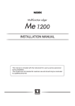
Length of trunk line
2.5Mbps
Specifications
625kbps
156kbps
No limited
8
35m
T-branch interval
Max. length of drop line
Overall length of drop lines
T-branch
connection
4m
15m
100m
500m
No limited
16m
50m
60m
200m
1.1mm
Insulator
thickness
Sheath
thickness
Conductor
resistance
(20 )
0.6mm
1.0mm
25.1Ω
/km
POINTS
B RATE
MODE
TEST
1
2
3
4
5
6
7
8
supply
adapter
Length of drop line
1
2
I/O
POINTS
3
5
Remote
station
Remote
station
Remote
station
Remote Terminating
station resistor
Remote
station
OFF
ON
OFF
ON
OFF
ON
OFF
OFF
ON
ON
OFF
OFF
ON
ON
OFF
OFF
OFF
OFF
ON
ON
ON
ON
625kbps
2.5Mbps
Setting prohibited*
OFF
ON
OFF
ON
OFF
OFF
ON
ON
8-point mode
4-point mode
16-point mode
Setting prohibited*
OFF
ON
OFF
ON
OFF
OFF
ON
ON
156kbps
6
7
MODE
TEST
OFF: ON LINE (Normal operation)
ON : Test mode (Self-loopback test)
* When the switch is set to this, ERR. LED will light up
3)
4)
Remote
station
Remote
station
Distance
between stations
Remote
station
48 pts.
ON
B RATE
Point mode
setting
8
Remote
station
32 pts.
OFF
Transmission
rate setting
4
64 pts. 128 pts. 256 pts. 512 pts. 1024 pts.
16 pts.
Test mode
Interval length of T-branch
Length
of
drop
Power
Terminating line
I/O points
occupied
ON
SW
I/O
Length of trunk line (Drop line not included)
Master station
resistor
Remarks
Cable length between 2
terminating resistors
(Drop line length not included)
Cable length per branch line
Total length of all drop lines
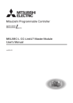
CC-Link/LT interface
connector
Serial number plate
Connector for CCLink/LT communication line connection
Indicates the serial No. of the QJ61CL12
POINT
Trunk line
Drop line
Remote
station
The settings of operation setting switches become valid when the module is turned ON from OFF
or when the programmable controller CPU is reset. When any of settings are changed with the
module powered ON, “ERR.” LED will blink. In this case, turn OFF and restart the system.
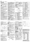
5. External Wiring
3. Mounting and installation
3.1 Precautions for handling
The precautions for handling the module are given below.
(1) The module is mode of resin. Do not drop or give it a strong impact.
(2) Do not remove the PCB (printed-circuit board) from the case. Doing so may cause
failure.
(3) When wiring, be careful not to let foreign matter such as wiring chips enter the
module inside. Remove it if this happens.
(4) The module has an ingress prevention label on its top to prevent foreign matter,
such as wire offcuts, from entering the module during wiring. Do not peel this label
during wiring. Before starting system operation, be sure to peel this label because
of heat dissipation.
(5) Tighten the module fixing screws within the following ranges.
Screw
Tightening torque range
Module fixing screw (M3 screw)*1
0.36 to 0.48N y m
The connection method of the CC-Link/LT connection cables is described below.
(1) The cables can be connected regardless of the order of the station number.
(2) Be sure to set the QJ61CL12 at the end of the trunk line. The terminating resistor
close to the QJ61CL12 should be connected within 20cm from the QJ61CL12.
(3) Connect terminating resistors to the both ends of the trunk line of CC-Link/LT without fail.
(4) For required number of the connectors, refer to the CC-Link/LT Master Module User's Manual.
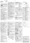
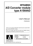
6. External Dimensions
*1: The module can be easily fixed onto the base unit using the hook at the top of the module.
However, it is recommended to secure the module with the module fixing screw if the
module is subject to significant vibration.
POINT
When removing the terminating resistor due to any system modification, be sure to
power OFF the system. Removing/Installing the terminating resistor with the power
ON may cause malfunctions (faulty input/output).
3.2 Installation environment
Refer to the User's Manual of the CPU module in use.
3.3 Cables, Connectors and Terminating Resistors
For inquires about the cables, connectors and/or terminating resistors, refer to the
following:
http://www.cc-link.org/
4. Name of Parts and Setting
1)
2)
1.2ms
4.3ms
15.6ms
*1: Performance of the CC-Link/LT cannot be guaranteed for use of cables other than the dedicated
flat cables, VCTF cables and high flexible cables.
*2: Set with the operation setting switch. (Refer to Chapter 4)
*3: Supplied through the dedicated power supply or power supply adapter.
*4: For VCTF cable specifications, refer to Table 2.1.
*5: Use the dedicated flat cables and high flexible cables accredited by the CC-Link Partner
Association.
http://www.cc-link.org/
Table 2.1
Item
Transmission rate
Distance between stations
Max. No. of stations on a drop line
Contents
Setting I/O points occupied, transmission rate, etc of QJ61CL12 (Factory
setting: OFF)
98 (3.86)
Thank you for purchasing the Mitsubishi general-purpose programmable
controller MELSEC-Q Series.
Before starting use, please read through this manual and the details manual to
ensure correct usage.
(1) Mitsubishi programmable controller ("the PRODUCT") shall be used in conditions;
i) where any problem, fault or failure occurring in the PRODUCT, if any, shall not lead to any
major or serious accident; and
ii) where the backup and fail-safe function are systematically or automatically provided outside of
the PRODUCT for the case of any problem, fault or failure occurring in the PRODUCT.
No.
Item
2) Operation setting
switches
3)
4)
No.
Item
1) LED indicator
QJ61CL12
RUN
SD
ERR.
L RUN
RD
L ERR.
Contents
Module condition is checked with LED status.
LED
Description
ON : Module operating normally
RUN
OFF : Fault in hardware
ON : Faulty switch setting
ERR.
Blink : Switched during operation
<When normal>
ON : Data link being executed
OFF: Data link stopped
L RUN
<In test mode>
ON : Self-loopback test resulted in normal
OFF: Self-loopback test failure
<Usually>
ON : Faulty data link station or station outside control range
detected
L ERR.
Blink
: Data link failure at all stations
<In test mode>
ON : Self-loopback test failure
OFF: Self-loopback test resulted in normal
SD
ON :Data being transmitted
RD
ON :Data being received
4
(0.16)
QJ61CL12 CC-Link/LT
Master Module
2.2 Network wiring specifications
The network wiring specifications of the CC-Link/LT are given below.
Operation setting switches
zCONDITIONS OF USE FOR THE PRODUCTz
90 (3.54)
23 (0.91)
27.4 (1.08)
Unit: mm (inch)
Warranty
Mitsubishi will not be held liable for damage caused by factors found not to be the cause of
Mitsubishi; machine damage or lost profits caused by faults in the Mitsubishi products;
damage, secondary damage, accident compensation caused by special factors unpredictable
by Mitsubishi; damages to products other than Mitsubishi products; and to other duties.