1
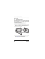
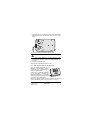
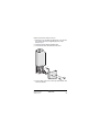
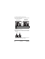
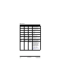
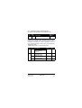
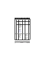
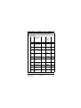
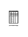
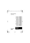
INSTALLATION MANUAL
Room thermostat
EKRTR
EKRTETS
1
2
1
2
±1.5
1.5 m
3
.2
m
0
>
3
5
34
125
28
4
161
170
60
87
4
5
50
EKRTR
EKRTETS
Room thermostat
Installation manual
Read this manual attentively before starting up the unit.
Do not throw it away. Keep it in your files for future
reference.
Improper installation or attachment of equipment or
accessories could result in electric shock, short-circuit,
leaks, fire or other damage to the equipment. Be sure
only to use accessories made by Daikin which are
specifically designed for the use with the equipment and
have them installed by a professional.
If unsure of installation procedures or use, always
contact your dealer for advice and information.
Contents
1. Introduction ............................................................................ 2
2. Installation of EKRTETS as floor temperature sensor............ 3
3. Installation of EKRTR ............................................................. 6
4. Setting up codes in the installer menu ................................. 14
5. Technical characteristics ...................................................... 22
EKRTR + EKRTETS
Room thermostat
4PW45518-1B
Installation manual
1
1. Introduction
The room thermostat EKRTR can be used to control floor
heating-only applications and floor heating/cooling applications.
It is typically connected to the indoor unit. Refer to the "Typical
application examples" in the Installation manual of the indoor
unit.
■ In case of floor heating-only applications the room
thermostat can also be connected to the individual motorized
valve of the floor heating loop.
■ If a floor heating-only application is used in combination with
fan coil units each fan coil unit should have its dedicated fan
coil thermostat.
Optionally, an external temperature sensor EKRTETS can be
connected to the thermostat and used as:
■ external ambient temperature sensor to control the room
temperature (instead of the temperature sensor inside the
thermostat). In that case, install the temperature sensor
where you want to control the ambient temperature.
■ floor temperature sensor to protect the floor temperature. In
that case, install the temperature sensor in the floor (refer to
"Installation of EKRTETS as floor temperature sensor" on
page 3).
Installation manual
2
EKRTR + EKRTETS
Room thermostat
4PW45518-1B
2. Installation of EKRTETS
as floor temperature sensor
As it should be integrated into the floor, the installation of the
temperature sensor EKRTETS should be planned and
performed in advance.
If EKRTETS is installed as floor temperature sensor, the
thermostat EKRTR should be wall-mounted. Refer to "Wallmounted installation" on page 6.
NOTE
1
The below procedure only serves as an example.
Your actual situation may differ from what is
represented here.
Take the installation suggestions for the thermostat into
account when selecting the installation location.
Refer to figure 3.
EKRTR + EKRTETS
Room thermostat
4PW45518-1B
Installation manual
3
2
Integrate the EKRTETS temperature sensor in an electrical
conduit (∅16 mm maximum) in the floor construction as
shown below.
Make sure to seal the temperature sensor electrical conduit
to protect the thermostat from hot air currents and to allow
the replacement of the temperature sensor.
1
2
3
3
1
Thermostat
2
Temperature sensor conduit (Ø16 mm maximum)
3
Temperature sensor EKRTETS (in conduit with seal)
4
Water pipes
Pass the temperature sensor cable through the conduit until
it reaches the seal.
Installation manual
4
4
EKRTR + EKRTETS
Room thermostat
4PW45518-1B
4
Connect the temperature sensor cable to the thermostat as
described in "Wall-mounted installation" on page 6.
NOTE
Install the temperature sensor as close as possible
to the floor loop inlet.
EKRTR + EKRTETS
Room thermostat
4PW45518-1B
Installation manual
5
3. Installation of EKRTR
You can mount the EKRTR thermostat on the wall or use it as
table-top model.
3.1.
Wall-mounted installation
The EKRTR thermostat can be wall-mounted, with supplied
screws and plugs. Refer to figure 1.
This is the case when you want to install the optional EKRTETS
as external temperature sensor.
1
At the left of the thermostat, gently push the lid.
2
Remove the front cover by pulling it towards you.
3
Optionally for the EKRTETS, unscrew the screw of the cable
holder in the bottom left corner of the back part of the
thermostat and remove the transparent cable protection.
4
Remove the battery insulator.
4
1
3
2
3
5
Drill holes in the wall taking the dimensions of the thermostat
into account and insert the supplied plugs in the holes.
Refer to figure 4 (unit of measurement: mm).
Installation manual
6
EKRTR + EKRTETS
Room thermostat
4PW45518-1B
6
Optionally, pass the temperature sensor wiring (EKRTETS)
through the back of the thermostat and wire it as shown
below.
7
Fasten the thermostat with the supplied screws.
Be careful not to pinch the wiring when fastening.
8
Optionally for the EKRTETS, put the transparent cable
protection back into place and fix the cable protection with
the screw.
9
Close the thermostat cover.
10 Remove the protective film from the LCD.
3.2.
Table-top installation of the thermostat
Only if the optional temperature sensor
EKRTETS is not installed as external
temperature sensor, the EKRTR can be
used as a table-top model.
In that case, no particular installation
for the thermostat is needed. The
thermostat functions as a complete
wireless unit and can be put anywhere
in the house into its table holder.
Remove the battery insulator and the protective film from the
LCD, as described in "Wall-mounted installation" on page 6.
EKRTR + EKRTETS
Room thermostat
4PW45518-1B
Installation manual
7
3.3.
Installation of the receiver
Typically the receiver needs to be installed next to the
AD indoor unit.
Recommendations
reception
for
an
optimum
signal
Take the installation suggestions for the receiver into account
when selecting the installation location and follow the
recommendations below.
■ Do not install the receiver inside a metal box.
■ Mount the receiver vertically, and minimum 10 cm away
from the AD indoor unit.
■ Mount the receiver minimum 10 cm away from any vertical
metal pipe or vertical electric circuit.
■ Mount the receiver at least 1.5 m above the ground.
Before obtaining access to terminals, all power
supply circuits must be interrupted.
Installation manual
8
EKRTR + EKRTETS
Room thermostat
4PW45518-1B
Keep the front clear at all times for access.
1
Drill holes in the wall taking the dimensions of the receiver
into account and insert the supplied plugs in the holes.
Refer to figure 5.
2
Fasten the receiver with the supplied screws.
3
Unscrew both screws and remove the front cover.
3
4
4
3
4
Unscrew both screws of the lower right cable bracket and
remove the bracket.
EKRTR + EKRTETS
Room thermostat
4PW45518-1B
Installation manual
9
5
According your application, perform the wiring.
5a When connected to the indoor unit, wire the indoor unit and
the receiver as shown below.
EKHB(H/X)007AC***
EKHB(H/X)008
EKHB(H/X)016
H C L N
H C L N
23 17 15 13
1 2 3 4 X2M
X1M H C
com
L N X2M
EKRTR receiver
H
Heating demand
C
Cooling demand
X1M H C
com
L N X2M
EKRTR receiver
For heating-only applications, wire 17-C or 2-C is not to be
installed.
Use wire size 0.75~1.50 mm2.
5b When connected to the motorized valve, wire the motorized
valve and the receiver as shown below (for heating-only
applications).
1N~50 Hz
230 VAC
L
N
X1M H C
com
1N~50 Hz
230 VAC
L N
L N X2M
EKRTR receiver
The output relays (H and C are voltage-free contacts) can
handle a maximum load of 100 mA - 230 VAC.
Installation manual
10
EKRTR + EKRTETS
Room thermostat
4PW45518-1B
Make sure to protect the power supply with a fuse of
3 A.
Select the power cable in accordance with relevant
local and national regulations.
A main switch or other means for disconnection,
having a contact separation in all poles, must be
incorporated in the fixed wiring in accordance with
relevant local and national legislation.
6
Put the cable bracket back into place and tighten the screws.
7
Close the receiver cover and tighten the screws.
Receiver-thermostat radio configuration
You need to configure the radio connection between the receiver
and the thermostat in order to make communication possible.
1 Put the receiver in radio configuration mode by pressing è
during 4 seconds.
The ! LED lights up green and the receiver is now waiting for
a thermostat configuration address.
If needed, you can simply exit this mode by pressing è
again.
2 Send the configuration address by going to code 5® 03 (®ƒ ‡≈î‹)
in the installer menu on the thermostat.
Refer to “Setting up codes in the installer menu” on page 14.
The thermostat will now send radio signals. On the LCD the
icon j flashes.
3 Verify that the radio signals are correctly received by the
receiver.
If the configuration is OK, the ! LED blinks green at each
radio signal received from the thermostat.
This also means that the receiver has left the radio
configuration mode.
4 On the thermostat, exit the installer menu by pressing > till
the "/" code is displayed and then pressing =.
5 Verify if the receiver is in thermostat mode and not in manual
mode by checking if the è LED is off.
Refer to "LED overview" on page 12.
EKRTR + EKRTETS
Room thermostat
4PW45518-1B
Installation manual
11
LED overview
è
§
OFF
RED
OFF
Thermostat mode:
Heating demand
OFF
GREEN
OFF
Thermostat mode:
Cooling demand
YELLOW
RED
OFF
Manual mode: forced
heating
YELLOW
GREEN
OFF
Manual mode: forced
cooling
YELLOW
OFF
OFF
Manual mode: forced
OFF
YELLOW/
OFF
GREEN/
RED/OFF
GREEN:
Quick
short blink
Communication
between receiver and
thermostat
YELLOW/
OFF
GREEN/
RED/OFF
GREEN:
continuous
Receiver in radio
configuration mode
OFF
OFF
GREEN:
slow blink
There is no longer
communication
between the receiver
and the thermostat
both heating and
cooling demand is
stopped. A manual
override is still
possible (refer to
"Manual control" on
page 13).
Installation manual
12
!
Meaning
EKRTR + EKRTETS
Room thermostat
4PW45518-1B
Manual control
You can use the receiver to manually override the heating or
cooling command of the thermostat when for example the
batteries of the EKRTR are empty or when the thermostat is
broken. Manual control is activated when the è LED lights up
yellow. In thermostat mode the è LED is off.
Thermostat mode
è LED is off
Press è
Manual mode:
forced heating
Red § LED
Yellow è LED
Press è
Manual mode:
forced cooling
Green § LED
Yellow è LED
Press è
Manual mode:
forced OFF
§ LED is off
Yellow è LED
Press è
EKRTR + EKRTETS
Room thermostat
4PW45518-1B
Installation manual
13
4. Setting up codes in the installer menu
You can set up codes, starting from the time and date menu (in
advanced mode).
NOTE
1
2
As a consequence of a customized configuration, it
is not abnormal that some codes are no longer
accessible.
Activate the advanced mode by pushing > during 5
seconds in OFF mode (D).
Navigate to the date and clock setting menu (G) by pressing
>.
3
Press > and keep it pressed while now pressing =
during 10 seconds.
y is displayed next to 4®.
4
Press < or > to consult the current settings of the
codes.
5
To modify codes, press +, - or =.
The value is flashing when being modified.
6
Press + or - to increase or decrease the code value by
1 step.
To put a code back to its default value, press + and - at
the same time.
7
Press = to save your selection.
You can exit this code menu by going to the "/" code and
pressing =.
Refer also to "Overview of all codes" on page 17.
Installation manual
14
EKRTR + EKRTETS
Room thermostat
4PW45518-1B
4.1.
Set-up for heating/cooling applications
For heating/cooling applications, set the following codes:
1st
code
2nd
code
Description
Required
setting
5®
01
Cooling mode present?
ÚêÒ
4.2.
Set-up floor temperature protection
If EKRTETS is installed as floor temperature sensor it can be
used to manage and thus protect the floor temperature. Refer to
"Installation of EKRTETS as floor temperature sensor" on
page 3. When this function is active the icon U flashes below the
ambient temperature.
To enable floor protection, set the following codes:
1st
code
2nd
code
5®
02
External temperature
sensor EKRTETS
installed?
ÚêÒ
—
7®
01
Enable floor high/low
temperature limit?
ÚêÒ
—
02
Lower limit of floor
temperature
18.0(a)
0.5°C
03
Upper limit of floor
temperature
35.0(a)
0.5°C
Description
Required
Step
setting
(a) default value. Can be modified as preferred.
EKRTR + EKRTETS
Room thermostat
4PW45518-1B
Installation manual
15
4.3.
Set-up for EKRTETS as external ambient
temperature sensor
EKRTETS can be used as external ambient temperature sensor
to control the room temperature (instead of the temperature
sensor inside the thermostat). In that case, install the external
temperature sensor where you want to control the ambient
temperature.
To enable the function, set the following codes:
1st
code
2nd
code
5®
02
External temperature sensor
EKRTETS installed?
ÚêÒ
6®
01
Selection of sensor for
temperature control: use
external ambient temperature
sensor?
ÚêÒ
NOTE
This function cannot be combined with floor
temperature protection.
Installation manual
16
Required
setting
Description
EKRTR + EKRTETS
Room thermostat
4PW45518-1B
4.4.
Overview of all codes
Following codes can be changed in the installer menu:
1st
2nd
code code
Description
Default
Range
Step
Readout codes
4®
01 + R Calibration of
temperature
sensor inside
the thermostat.
Actual
temperature +
offset are
displayed. The
h symbol
appears when
the offset
deviates from 0.
02 + U Calibration of
external
temperature
sensor. Actual
temperature +
offset are
displayed. The
h symbol
appears when
the offset
deviates from 0.
03
Offset = 0 Offset:
–5°C~5°C
0.1°C
Offset = 0 Offset:
–5°C~5°C
0.1°C
Calibration of
Offset = 0 Offset:
1%
humidity sensor.
–10°C~10°C
Actual humidity
+ offset are
displayed. The
h symbol
appears when
the offset
deviates from 0.
EKRTR + EKRTETS
Room thermostat
4PW45518-1B
Installation manual
17
1st
2nd
code code
Description
Default
Range
Step
Installation codes
5®
01
Cooling mode
present?
≈œ
ÚêÒ/≈œ
—
02
External
temperature
sensor
EKRTETS
installed?
≈œ
ÚêÒ/≈œ
—
03
—
®ƒ ‡≈î‹ and j
are displayed
on the LCD.
This code is
used during the
receiverthermostat
radio
configuration.
Refer to
"Receiverthermostat
radio
configuration"
on page 11.
—
—
ÚêÒ (use
—
Temperature control codes
6®
01
Selection of
sensor for
temperature
control: use
external
ambient
temperature
sensor?
Installation manual
18
≈œ
external
temperature
sensor)/
≈œ (use
temperature
sensor
inside the
thermostat)
EKRTR + EKRTETS
Room thermostat
4PW45518-1B
1st
2nd
code code
Description
Default
Range
Step
Daikin advizes not to change below temperature control
parameters. They are set for an optimal use of the floor cooling/
heating application.
6®
Use proportional
band control?
ÚêÒ
Hysteresis value
03
04 + p Duration
00.5
020
02
—
ÚêÒ
(proportional
band)/≈œ
(hysteresis)
00.5~02.0
010~060
0.1°C
002~ 6® 04/2
1 min.
003
001~ 6® 04/2
1 min.
020
010~060
1 min.
002~ 6® 07/2
1 min.
001~6® 07/2
1 min.
1 min.
proportional band
(heating).
05 + p Minimum "on" time 007
(heat demand).
06 + p Minimum delay
between 2 heating
cycles.
07 + o Duration
proportional band
(cooling).
08 + o Minimum "on" time 007
(cool demand).
09 + o Minimum delay
003
between 2 cooling
cycles.
10
Value of
02.0
proportional band.
01.0~04.0
0.1°C
11
Compensating
value.
00.0
00.0~08.0
0.1°C
12
Upper setpoint
limitation.
37.0
22.0~37.0
0.5°C
13
Lower setpoint
limitation.
04.0
04.0~20.0
0.5°C
EKRTR + EKRTETS
Room thermostat
4PW45518-1B
Installation manual
19
1st
2nd
code code
Description
Default
Range
Step
Floor temperature limit
7®
01
Enable floor
high/low
temperature
limit?
≈œ
ÚêÒ/≈œ
—
02
Lower limit of
floor
temperature.
18.0
05.0~Upper
limit (7® 03)
0.5°C
03
Upper limit of
floor
temperature.
35.0
Lower limit
(7® 02)~50.0
0.5°C
ÚêÒ/≈œ
—
Schedule timer codes
8®
01
Enable cooling/ ≈œ
heating link for
the user-defined
schedules ◊1
and ◊2?
When enabled
and a userdefined
schedule is
selected in the
schedule timer
setting menu:
in heating
mode, schedule
◊1 will be active;
in cooling
mode, schedule
◊2 will be active.
Installation manual
20
EKRTR + EKRTETS
Room thermostat
4PW45518-1B
1st
2nd
code code
Description
Default
Range
Step
ÚêÒ/≈œ
—
ÚêÒ/≈œ
—
ÚêÒ/≈œ
—
—
—
Miscellaneous codes
9®
01
Daylight saving ÚêÒ
time
implementation.
02 + p Forced heating ≈œ
(installation
check).
03 + o Forced cooling ≈œ
(installation
check).
Reset all
—
15 +
®êÒê‹æ¬¬ settings back to
factory
configuration.
Press =
during 5
seconds. The
complete LCD
is shown to
confirm all
settings are
reset.
EKRTR + EKRTETS
Room thermostat
4PW45518-1B
Installation manual
21
5. Technical characteristics
5.1.
EKRTR - Thermostat
Temperature read out
Steps of 0.1°C
Operating temperature
0°C~50°C
Setpoint temperature
range
4°C~37°C in steps of 0.5°C
Electrical protection
Class II - IP30 (indoor use, polution
degree 2)
Feeding and autonomy
3 alkaline batteries AA.LR6 1.5 V
approximately 2 years (depending
on usage conditions)
5.2.
EKRTR - Receiver
Operating temperature
0°C~50°C
Electrical protection
Class II - IP44 (indoor use, polution
degree 2)
Power supply
1N~50 Hz 230 VAC
Radio frequency and
receiving zone
433.92 MHz, <10 mW.
Range of approximately 100 m in
open space.
Range of approximately 30 m in
residential environment.
Output relays
Maximum load 100 mA - 230 VAC
Maximum fuse amp
3A
Power consumption
15 W, maximum.
Immunity against voltage
surges
Category III (2.5 kV)
Type of automatic action
of the thermostat
1C
5.3.
EKRTETS (optional)
External temperature
sensor
Installation manual
22
NTC 10K at 25°C/3 meter lead
EKRTR + EKRTETS
Room thermostat
4PW45518-1B
NOTES
4PW45518-1B
Copyright © Daikin