1
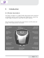
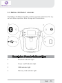
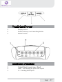
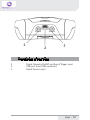
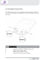
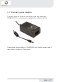
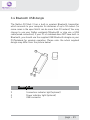
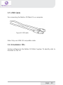
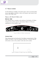
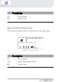
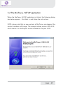
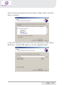
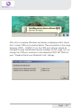
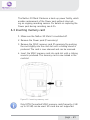
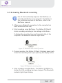
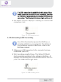
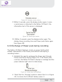
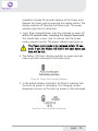
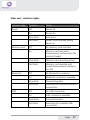
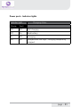
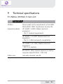
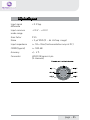
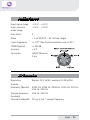
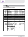
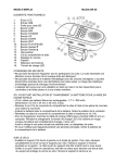
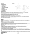
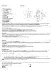
NeXus-10 Mark II
Hardware & Software Installation Manual
Version 1.0 - August 2011
Contents
1 .Introduction...................................................................................................... 5
1.1 Product description.................................................................................5
1.2 About this manual...................................................................................6
1.3 Explanation of symbols..........................................................................7
2 .Safety................................................................................................................ 8
2.1 General safety...........................................................................................8
2.2 User qualification.....................................................................................8
2.3 Limitations of use....................................................................................9
2.4 Warnings................................................................................................. 10
2.5 Safety measures................................................................................... 12
2.6 Precautionary measures..................................................................... 13
2.7 Environmental conditions................................................................... 14
3 .NeXus-10 Mark II system parts..................................................................15
3.1 NeXus-10 Mark II encoder................................................................. 16
3.2 The NeXus Power Pack....................................................................... 19
3.3 The main power adapter..................................................................... 20
3.4 Bluetooth USB dongle......................................................................... 21
3.5 USB Cable.............................................................................................. 22
3.6 Installation CDs..................................................................................... 22
3.7 Device labels.......................................................................................... 23
4 .Description.....................................................................................................25
4.1 Intended use.......................................................................................... 25
4.2 System description............................................................................... 26
4.3 Principles of operation......................................................................... 27
page - 2
5 .Software Installation.....................................................................................28
5.1 BioTrace+ and driver software........................................................... 28
5.2 The BioTrace+ SETUP application..................................................... 29
5.3 Computer System Requirements...................................................... 32
5.4 USB Driver Installation........................................................................ 33
5.5 Bluetooth Pairing (Windows 7).......................................................... 47
5.6 Bluetooth Pairing (Windows XP)....................................................... 51
5.7 BioTrace+ concise Quickstart Guide.................................................. 55
6 .Operation........................................................................................................59
6.1 Recharging Power pack....................................................................... 59
6.2 (Re)placing Power pack....................................................................... 59
6.3 Inserting memory card........................................................................ 61
6.4 Switching on.......................................................................................... 62
6.5 Switching off.......................................................................................... 63
6.6 Display of device information............................................................. 63
6.7 Activating memory card recording.................................................... 65
6.8 Establishing a Bluetooth connection................................................ 67
6.9 Activating Bluetooth recording........................................................... 68
6.10 Establishing a USB connection........................................................ 69
6.11 Activating USB recording.................................................................. 70
6.12 Activating Bluetooth/USB recording with
memory card logging.................................................................................. 71
6.13 Exchange of Power pack during recording................................... 75
7 .Troubleshooting.............................................................................................78
8 .Maintenance...................................................................................................82
page - 3
9 .Technical specifications................................................................................84
9.1 NeXus-10 Mark II main unit.............................................................. 84
9.2 Power supply......................................................................................... 89
9.3 Bluetooth dongle.................................................................................. 89
9.4 General.................................................................................................... 90
10 .Electromagnetic guidance..........................................................................91
11 .Warranty and Support...............................................................................94
Warranty........................................................................................................ 94
Questions, technical assistance and support......................................... 95
Contact........................................................................................................... 95
BioTrace Software: Warnings & Disclaimers.......................................... 96
Limitation of liability.................................................................................... 97
DECLARATION of CONFORMITY............................................................... 98
page - 4
1 Introduction
1.1 Product description
The NeXus-10 Mark II is a highly flexible physiological data acquisition
and feedback platform with 8 analog and 2 digital inputs, supporting
a wide range of sensors for more than 10 input channels.
The picture below summarizes the main features and the advanced
design of this high precision instrument.
page - 5
1.2 About this manual
This manual contains information on:
- installation of your NeXus
- using/operating your NeXus
- maintenance of your NeXus
- installation of the USB and Bluetooth drivers
- installation of the BioTrace+ Software
In this manual, the NeXus-10 Mark II system is from here-on after
referred to as: “your NeXus“.
Your NeXus is designed to be used in combination with a (personal)
computer. Please refer to the installation of the drivers and software
for information on the requirements of this computer.
How to use this manual
Please notice the following:
- read this manual carefully BEFORE installing and using
your NeXus.
- Follow the instructions in the given sequence.
- Keep a copy of this manual near your NeXus.
page - 6
1.3 Explanation of symbols
In this manual or on labels used on your NeXus, you may find one or
more of the following symbols. Their meaning is as follows:
Manual contains important safety information
Device has type BF applied parts
Special EU instructions for disposal are applicable
to a product on which this symbol is placed. See the
Maintenance section of this manual.
Identification of the manufacturer.
This device contains a RF transmitter
This device contains a Bluetooth transmitter
This device meets applicable EU requirements, refer
to “Declaration of Conformity”
Attention: read important safety information
Important information / guidance for use
Direct current
USB component
page - 7
2 Safety
2.1 General safety
Read this section carefully, failure to do so may, in rare cases, result in
personal injury or property damage.
There are no known side effects from the use of this equipment.
The following 2 lines are only applicable to the U.S.A.:
- Under federal law this equipment may only be sold by or on the
order of a physician or licensed practitioner.
- The equipment may only be used under the constant supervision
of or on the instructions of a physician or other authorized medical
professional.
2.2 User qualification
The equipment is intended to be used by or under the direction of a
physician (clinician) or a researcher.
The user must have knowledge of current good practice in physiological measurements for scientific and clinical applications.
page - 8
2.3 Limitations of use
WARNING:
Your NeXus is NOT intended for
- critical patient monitoring
- use in life support systems
- Equipment is not to be used near MRI equipment.
- Equipment is not to be exposed to ionizing radiation.
- Equipment is not to be used on patients undergoing electro surgery
- The equipment is not defibrillator proof.
- Equipment is not to be used in oxygen rich environments (concentration > 25 % at 1 atm).This system is not suitable for use in an
inflammable mixture of anesthetics and air, oxygen or nitrous oxide.
- Do not immerse the system in any liquid.
Apart from the above, there are no contra-indications.
page - 9
2.4 Warnings
Electrical Safety Warnings
As a result of the approval of the NeXus-10 Mark II to IEC60601-1,
the following warnings are applicable:
IEC60601-1 compliance is the responsibility of the end user !
To ensure compliance to IEC60601-1, the NeXus-10 Mark II system
must meet the following conditions:
1. The PC and peripherals (e.g. USB hubs) must comply with
IEC60950 or equivalent, and must be located outside the patient
environment;
AND
2. The enclosure leakage current from any device within the
patient environment, including any parts of equipment which extend
into that environment, is not more than 0.1 mA in normal condition and 0.5 mA in the single fault condition of interrupting an earth
conductor in any single power supply cord (for the USA the single fault
limit is reduced to 0.3 mA).
The required low enclosure leakage current may be achieved by powering the PC and peripherals from an isolation transformer. It is not
recommended that the equipment be connected to other non-isolated
monitoring equipment or communication networks. In this event it is
the end user’s responsibility to ensure compliance with IEC60601-1.
The patient environment is defined as the area within 1.5 m (approx.
6 ft) of the patient.
page - 10
Warning
-
The manufacturer cannot guarantee safety and performance
of the system when used in conjunction with accessories that are not
manufactured or approved by the manufacturer.
If liquids or moisture penetrate any part of the system,
disconnect the affected part from all other system parts. If in doubt
about safety or performance of the equipment, have it checked by the
manufacturer.
Do not expose the system to direct sunlight, heat from a
source of thermal radiation, excessive amount of dust, moisture,
vibration, or mechanical shock.
Do not wind the cables in a loop smaller than 5 cm or bend
them sharply, this may damage the cables.
In case of obvious damage to any part of the equipment, immediately disconnect it from the patient and/or do not use.
Do not incinerate any part of the equipment
page - 11
2.5 Safety measures
Warning
The only mains power adapter that may be used is the original adapter, type Meanwell GS18A12-P2L, included in the equipment.
Do NOT replace it with anything else. If any other type of mains power
supply is used neither safety nor correct operation of the equipment
can be guaranteed.
Make sure the computer is installed according to local regulations and safety precautions.
If the computer is equipped with a safety earth conductor, use
it and connect it to a well-earthed wall socket.
Do not connect active sensors or electrodes to any of the
inputs unless they have been approved by the manufacturer.
No modification of this equipment is allowed.
The patient must not touch the connector of the Power pack.
The operator must not touch the patient and connector of the
Power pack simultaneously.
Do not place the mains power adapter in the patient environment, i.e. within typically 1.5 meters from the patient.
page - 12
2.6 Precautionary measures
Warning
-
Disposable electrodes which are used for electrophysiological
measurements may constitute a biohazard. Handle, and when applicable dispose of these materials in accordance with accepted medical
practice and any applicable local, state and federal laws and regulations.
-
Reusable electrodes present a potential risk of cross-contamination. Please refer to the documentation that came with your
electrodes for instructions on how to prevent this.
-
The NeXus-10 Mark II main unit and Power pack should not
come into longer contact with mucous membranes, body liquids or
roughened skin.
-
The NeXus-10 Mark II main unit connectors contain nickel,
avoid prolonged skin contact with patients with nickel allergy.
-
Take care in arranging patient and sensor cables to avoid
patient entanglement or strangulation.
page - 13
2.7 Environmental conditions
Warning
Do not use, store or transport the equipment outside the specified
environmental conditions, this may damage the equipment.
Limits
Usage temperature
+10 °C … +40 °C (recommended)
Storage temperature
+10 °C … +30 °C
Battery limit: max 30 °C for 6 months.
Transport temperature
-10 °C … +45 °C
Battery limit: max 45 °C for 1 month.
Humidity (non-condensing)
10 % ... 90 %
Pressure
500 hPa … 1060 hPa
page - 14
3 NeXus-10 Mark II system parts
Please verify the contents of your purchase by comparing with the
list below, to check whether all NeXus-10 Mark II system parts are
present.
Description of system parts
1
NeXus-10 Mark II main unit (see 3.1)
2
Power pack (see 3.2)
3
Mains power adapter (see 3.3)
4
Bluetooth USB dongle (see 3.4)
5
USB cable (see 3.5)
6
Installation CDs (see 3.6)
7 Documentation
Actual items may differ from this typical scope of delivery. Check the
package list for actual package contents.
In case of unexpected package contents, contact Mind Media support.
page - 15
3.1 NeXus-10 Mark II encoder
The NeXus-10 Mark II encoder contains precision electronics for signal and data acquisition, data storage and transmission.
Description of encoder indicator lights
1
Bluetooth indicator light
2
Power on/off indicator light
3
USB indicator light
4
Memory card indicator light
page - 16
Description of buttons
1
2
3
Display button
Power/ Memory card recording button
Marker button
Description of front view
1
2
3
Patient/Client Ground input (Gnd)
A&B - C&D analog bi-polar EXG inputs
E – H analog AUX inputs
page - 17
Description of rear view
1
2
3
Digital Oximetry (SpO2) and Event/Trigger input
USB port (mini USB connector)
Digital Sensor input
page - 18
3.2 The NeXus Power Pack
The NeXus Power pack is a rechargeable battery, based on state of
the art Lithium Polymer technology, for use with the NeXus-10 Mark
II encoder.
Description
1
2
3
4
Connector to NeXus-10 Mark II main unit
Battery fault indicator light
Battery charge indicator light
Connector for mains power adapter
page - 19
3.3 The main power adapter
Provides power to recharge the Power pack. Type Meanwell
GS18A12-P2L, see label on the adapter for technical details.
Please note: the procedure of CHARGING your NeXus power pack is
described in Chapter 6. (Operation)
page - 20
3.4 Bluetooth USB dongle
The NeXus-10 Mark II has a built-in wireless Bluetooth transmitter
which connects to your computer for distances of up to 10 meters. (in
some cases in the open field it can be more than 10 meters). You may
choose to use your NeXus wirelessly (Bluetooth) or else use a USB
cable (wired connection). If your PC or notebook does NOT have built-in
Bluetooth, you should use the supplied USB Bluetooth dongle on your
PC/Notebook for wireless operation. Please note: the actual supplied
dongle may differ from the picture below!
Description
1
2
3
Connection indicator light (optional)
Power indicator light (optional)
USB connector
page - 21
3.5 USB Cable
For connecting the NeXus-10 Mark II to a computer.
Figure 8: USB cable
Note: Only use USB 2.0 compatible cable.
3.6 Installation CDs
Contain software for the NeXus-10 Mark II system. To identify, refer to
the label on the CD.
page - 22
3.7 Device labels
For identification of NeXus-10 system parts, there are three labels:
two on the NeXus-10 Mark II main unit (exterior and interior) and
one on the Power pack.
Nexus-10 Mark II Main unit
Exterior label
The outside label is located on the bottom of the NeXus-10 Mark
II device and contains generic information. Refer to 1.3 for an
explanation of the symbols used.
Figure 9: NeXus-10 Mark II outside label
Interior label
The interior label can be found in the battery compartment of the
NeXus-10 Mark II, near the memory card slot. It contains specific
information such as the product code and serial number.
Figure 10: NeXus-10 Mark II main unit inside label
page - 23
Description
SN
Serial number
REF
Product code
Nexus-10 Mark II Power pack
The Power pack label is placed on the bottom of the Power pack.
Figure 11: Power pack label
Description
SN
Serial number
Input
Power supply requirements
REF
Product code
page - 24
4 Description
4.1 Intended use
The NeXus-10 Mark II system is intended to
- acquire high quality bio-electrical and other physiological
signals
- transfer these signals to a computer for processing and
analysis
The system is designed for measuring a wide range of physiological
signals. These signals include EEG, EMG, ECG, respiration, temperature, oxygen saturation and signals that describe body movement.
The system is intended for use on humans.
The system is intended for use in a laboratory or home environment.
Only use the equipment with the supplied accessories. In case other
parts or accessories are required, contact Mind Media support for
information.
page - 25
4.2 System description
The NeXus-10 Mark II system is a general purpose signal acquisition
system for high-quality physiological measurements. It is intended
for use with the BioTrace+ application software for data analysis and
presentation.
The NeXus-10 Mark II main unit (NeXus-10) contains the electronics
for amplification, digitization, storage, and wireless transmission. The
NeXus-10 Mark II uses an exchangeable Power pack as power supply. Sensors and electrodes simultaneously connect to the NeXus-10
Mark II.
The Power pack is charged (while not connected to the NeXus-10
Mark II) through a mains power adapter. The NeXus-10 Mark II is
able to interface through USB or wireless Bluetooth connection to a
computer. The latter requires installation of the Bluetooth dongle on a
USB 2.0 port of the computer. In addition, NeXus-10 Mark II is capable of storing measurement data on a SDHC memory card.
page - 26
4.3 Principles of operation
The NeXus-10 Mark II contains true DC amplifiers with very low input
noise, very high input impedance and very high common mode rejection.
Use of special electrode leads and active guarding minimizes movement artifacts. The amplifier is very insensitive to 50/60 Hz mains
power interference.
The NeXus-10 Mark II runs on a Power pack, which contains a
rechargeable lithium-polymer battery. It can store data on an SDHC
memory card and/or transmit real-time data to the computer by
means of a Bluetooth or USB connection.
Application software (BioTrace+) installed on the computer controls
the NeXus-10 Mark II’s measurement functions.
For more detailed technical information about the operating principles
of the equipment, contact Mind Media support.
page - 27
5 Software Installation
5.1 BioTrace+ and driver software
The BioTrace+ software setup CD shipped with your NeXus contains a
SETUP application, called SETUP.EXE which will automatically startup when you insert the CD/DVD into your computer.
When it does not start automatically, please start it manually by double clicking the SETUP.EXE via the explorer menu.
SETUP will install the following:
1 The Mind Media BioTrace+ software plus all its content.
2 The BioTrace+ software user guide/manual (PDF format)
3 The USB drivers for your NeXus.
This means that when you follow the steps of the BioTrace+ installation procedure, all of this will be done automatically. The only
last step that you will need to do manually, is the installation of the
Bluetooth-link to your computer, this is also called “pairing“.
Note: The Bluetooth pairing is described in chapter 5.4
page - 28
5.2 The BioTrace+ SETUP application
When the BioTrace+ SETUP application is started, the following dialog
box below appears. Click Next >> and follow the instructions.
NOTE: please note that as new versions of BioTrace+ are released, the
version numbers will change. This example shows version 2011A UK,
which means it is the English version released in the year 2011.
page - 29
Next, the license agreement will be shown. Please read it and click
next to continue...
In the next dialog box you may choose the directory or path where
BioTrace is installed. We advise to use the suggested path!
page - 30
Keep clicking Next>> until the actual software installation begins. You
will then see a dialog box like this. Please wait for it to finish.
When the installation is complete, you will see a dialog box like this.
After you click on ‘Exit’ the USB driver will be installed automatically.
page - 31
5.3 Computer System Requirements
IO and interfacing
- At least one available USB 2.0 port.
- Make sure no Bluetooth driver (other than the Microsoft
Bluetooth driver) is installed on your computer.
Windows operating systems
The following operating systems are supported:
* Windows 7 (32 and 64 bits)
* Windows XP (32 bits)
Note: Administrator rights are required to complete this procedure in Windows 7.
Note: Windows Vista may work, but is not recommended.
PC/Computer hardware
We advise the following minimum requirements:
- 2 GB system memory (RAM)
- 2 Ghz processor (dual or multi-core recommended)
- 200 GB space available on your harddisk. (for session data)
For more details, please refer to the electronic version (PDF) of the
BioTrace+ software manual.
page - 32
5.4 USB Driver Installation
The USB driver installation will be automatically started by
the BioTrace+ SETUP application after the BioTrace+ installation has completed.
If you however need to (re)install the USB driver manually, please
locate the driver software on the SETUP CD/DVD and follow the steps
below. For the automatic installation you can skip the next two pages
and read further on the page where the dialog box “Welcome to the
Mind Media Driver Installer“ is shown.
Manual Installation steps
1 First install NeXus-10 Mark II driver software onto the computer as described in 5.3. This means: BEFORE connecting
the USB cable to the NeXus and the computer!
2 Connect the power plug of the mains power adapter to a
wall socket. Charging of the Power pack begins.
3 As soon as charging of the Power pack is complete (see 6.1),
disconnect the mains power adapter and place the Power
pack in the NeXus-10 Mark II main unit (see 6.2)
4 Perform the Bluetooth device pairing procedure between
NeXus-10 Mark II and computer. For Windows 7, see 5.4.
For Windows XP see 5.5.
5 Installation is complete; the NeXus-10 Mark II is now ready
for use.
page - 33
Manual Installation of the USB driver
To install the USB driver manually: locate the USB driver software on
the SETUP CD/DVD. Normally this is located in the \DRIVERS directory in the root drive.
- \DRIVERS contains the USB drivers
Double-click “MM_Driver_Installer.bat” to start the USB driver installation manually.
When this Dialogbox appears, please click YES to continue...
page - 34
After this, in the background a “command window” may appear. From
this point on, the instructions are the same for the automatic and
manual installation of the USB driver.
Click “Next”.
page - 35
Click “I accept this EULA”.
Click “Next”.
page - 36
A Windows Security popup shows a warning about the publisher of
the driver software.
Click “Always trust software from “Mind Media BV” and click “Install”.
The first step of the ‘driver installation’ is now completed. Click ‘Finish’.
page - 37
Now connect the NeXus-10 Mark II to the computer, by connecting
the USB cable to the NeXus-10 Mark II main unit and to a USB 2.0
port on your computer.
Next, you will see the following picture in the bottom right corner of
your screen:
When the second step of the ‘driver installation’ is finished, a popup is
shown:
The USB driver installation is now complete.
page - 38
Installation for Windows XP
NOTE: administrator rights are required to complete this procedure.
For installation of the Bluetooth dongle, a working internet connection
to www.microsoft.com is required for retrieving the Microsoft Bluetooth driver.
Insert the installation CD in the CD/DVD drive of your PC and wait
until the installer screen is shown.
If the “The manufacturer Driver Installer” window does not appear
within 30 seconds, click the Start menu, click My Computer, right-click
your CD/DVD drive, and then click AutoPlay.
Click “Next”.
page - 39
Click “I accept this EULA”. Click “Next”.
page - 40
Wait until the next screen is shown:
The first step of the ‘driver installation’ is now completed.
For the second step of the ‘driver installation’ connect the USB cable
(see Figure 2) to the NeXus-10 Mark II main unit and to a USB 2.0
port on your computer.
The ‘Found New Hardware Wizard’ is shown.
page - 41
Click ‘No, not this time’ and ‘Next’.
Click ‘Install the software automatically’ and ‘Next’.
page - 42
Click ‘Finish’ to complete the second step of the ‘driver installation’.
When you have clicked ‘Finish’, you will see the next picture near the
right bottom corner of your screen:
page - 43
Connect the Bluetooth dongle (see Figure 1) to an USB 2.0 port of
your computer.
When you have done this, you will see the next picture near the right
bottom corner of your screen:
The ‘Found New Hardware Wizard’ is shown.
page - 44
Click ‘Yes, this time only’ and ‘Next’.
The wizard now searches for the Microsoft Bluetooth driver at www.
microsoft.com.
The wizard installs the Microsoft Bluetooth driver.
page - 45
The driver software is now installed.
Click ‘Finish’.
The Bluetooth dongle is now installed. The driver installation procedure is now successfully completed.
AFTER this hardware installation you can PAIR (connect) the NeXus
via Bluetooth to your computer. The following chapters describe this.
page - 46
5.5 Bluetooth Pairing (Windows 7)
Connecting a wireless Bluetooth device to your computer is
called “pairing“ and it requires a so called passkey or pincode
which typically consists of 4 numbers.
The following pages describe the Bluetooth pairing procedure for
microsoft Windows 7. The pairing procedure for Windows Vista looks
very similar and is not shown here.
First LOCATE the small Bluetooth icon in your taskbar. (usually at the
left bottom of your windows desktop.
Right-click it with your mouse and choose “Add a Bluetooth Device“
Make sure your NeXus is ON and the Bluetooth dongle is connected
to your PC. Windows will find your NeXus and displays its serial no.
Use the last 4 digits (0002 in this example) and use it as the Passkey.
page - 47
Enter your passkey (last 4 digits of your NeXus serial number)
page - 48
After this is complete, Windows will display a dialogbox which shows
the 2 virtual COM ports used by NeXus. These should be in the range
between COM1 - COM30. If not, the COM port settings should be
changed through the Windows device manager to this range. You can
change the COM port numbers in the advanced PORT SETTINGS of
your “Standard Serial over Bluetooth Link“ settings.
page - 49
BlueTooth pairing & the wired USB link
After this dialog box is shown, your NeXus BlueTooth pairing is complete. Please note the following:
- Your computer will remember your NeXus pairing and will automatically find your NeXus when you switch it on.
- You may pair your NeXus to several computers, but the first one that connects for a live recording will get exclusive access to the data stream.
- If your NeXus is connected to a computer via a USB cable, it will use the wired USB connection instead of the wireless BlueTooth. connection.
page - 50
5.6 Bluetooth Pairing (Windows XP)
Mind Media advizes you to use Windows 7 or later. For backward compatibility we have included the Bluetooth installation
for Windows XP, which should be version SP2 or later.
First LOCATE the small Bluetooth icon in your taskbar. (usually at the
left bottom of your windows desktop.
Right-click it with your mouse and choose “Add a Bluetooth Device“
page - 51
Switch your Nexus ON and follow the instructions...
page - 52
Windows will show your NeXus after it has been found. Enter the last
4 digits (“0002” in this example) of the serial code as the passkey.
page - 53
The next dialogbox will show the scanning process. Once the wireless
connection of your NeXus has been found, the “Found new Hardware“
message will be shown in the left bottom (notification area) by microsoft Windows.
After this is complete, Windows will display a dialogbox which shows
the 2 virtual COM ports used by NeXus. These should be in the range
between COM1 - COM30. If not, the COM port settings should be
changed through the Windows device manager to this range. You can
change the COM port numbers in the advanced PORT SETTINGS of
your “Standard Serial over Bluetooth Link“ settings.
page - 54
5.7 BioTrace+ concise Quickstart Guide
After the BioTrace+ software has been installed on your computer, you can start using it. The information on the following
pages will get you started and will inform you where you can
find the electronic version (PDF) of the BioTrace+ software
manual, which provides in-depth information.
You will need a recent version of the Adobe Acrobat reader
software to read this PDF file.
Go to your Windows START button (typically found at the left
bottom corner of the desktop) and start the BioTrace+ software. You can also open the software manual via this menu.
page - 55
After starting up, BioTrace+ will state its version and display
the BioTrace+ MAIN MENU.
We advise you to try out the various HELP menu items, such
as the software manual and the instruction videos.
page - 56
Please read the electronic version of the software manual before proceeding. After that we advise you to take a look at the
point and click protocols. A good point to start are the DEMO
protocols which demonstrate various sensors and signals.
Other options you will find here are the Biofeedback and
Neurofeedback protocols, which provide an easy way to get
started.
BioTrace+ software updates
Please note: future BioTrace+ software versions may display
different content as shown in these examples. You can download BioTrace+ updates through the Mind Media website.
page - 57
Below an example is shown from the DEMO protocols. Just
point and click at the various protocols and read the information they provide.
The concise quick-start guide ends here. Please refer to the
electronic version of the BioTrace+ software manual for all
further details on BioTrace+.
Last but not least; we advise you to become a member of the
NeXus user groups/forums on the Internet. In the BioTrace+
HELP menu you will find several examples of existing forums.
On our Mind Media website you will find more information
about NeXus, workshops, events, newsletters and more.
We look forward to hearing from you! WWW.MINDMEDIA.INFO
page - 58
6 Operation
This section describes the main functions of the NeXus-10 Mark II.
Prerequisites
1. Make sure that all software is installed on the computer
according to the instructions in (see 5).
2. Refer to the corresponding user manuals for information.
N.B.: The BioTrace+ software suite needs to be installed on the
computer in order to use the NeXus-10 Mark II. Refer to the BioTrace
installation manual. For more information on BioTrace+, contact Mind
Media support.
6.1 Recharging Power pack
1. Connect the Power pack to the mains power adapter.
2. Connect the mains power adapter to a wall socket.
The charge indicator light will switch on.
3. The Power pack is fully charged as soon as the charge
indicator light is switched off.
6.2 (Re)placing Power pack
1. In case a Power pack is present on the NeXus-10 Mark II:
release the Power pack by pressing the release button as
indicated in Figure 12.
2. Remove the Power pack.
page - 59
Figure 12: Placement of the Power pack
3. Insert a (fully charged) Power pack (Figure 12, in reverse
sequence). You should hear a clear ‘click’ to indicate that
the Power pack is placed correctly. The device is now ready for use.
page - 60
The NeXus-10 Mark II features a back-up power facility, which
enables replacement of the Power pack without interrupting an ongoing recording session. For details on replacing the
Power pack during recording, see 6.14.
6.3 Inserting memory card
1. Make sure the NeXus-10 Mark II is switched off.
2. Remove the Power pack (if necessary).
3. Remove the SDHC memory card (if necessary) by pushing
the card slightly into the card slot until a clicking sound is
produced. The card is now released and can be removed.
4. Insert the SDHC memory card into card slot until a clicking
sound is produced. The memory card is now locked in the
card slot.
Figure 13: Inserting memory card
Only FAT32 formatted SDHC memory cards (capacity 4 GB
up to 32 GB) can be used. SD cards are not supported.
page - 61
5. Put the Power pack back in place.
6.4 Switching on
1. Press the power/memory card recording button for more
than 0.5 seconds. The NeXus-10 Mark II will start. A startup message appears on the display.
Figure 14: Start-up message
2. To save battery power, the display will shut off automatically
after 5 seconds. To reactivate the display at any time, press
the display button.
3. If a memory card with valid measurement configuration file
is detected, the memory card indicator light switches on.
In case a memory card with invalid measurement configuration file (see 6.5) is present during start-up, the NeXus-10
Mark II displays an error message. The memory card recording indicator light blinks fast. Remove the memory card or replace it
with one that has a valid measurement configuration file.
Figure 15: Invalid measurement configuration file error message
page - 62
6.5 Switching off
1. Press the power/memory card recording button for more
than 0.5 seconds but no longer than 3 seconds (pressing
the button for more than 3 seconds activates memory card
recording, see 6.7). A shutdown message is displayed.
Figure 16: Shutdown
2. Auto power off: if the NeXus-10 Mark II is not recording, it
automatically switches off after 10 minutes if no buttons
are pressed.
6.6 Display of device information
1. Make sure the NeXus-10 Mark II is switched on and not
recording (for display of device information during recording,
see 6.12). The display is off.
2. Press the display button. The display shows current date,
time and Power pack status.
Figure 17: Default display
3. Within 5 seconds, press the display button again. If a memory card
is inserted, the NeXus-10 Mark II displays memory card configuration
and status.
page - 63
Figure 18: Memory card configuration and status
If a timed acquisition has been programmed in the configuration file, the start date, start time and duration is
displayed.
For details on programming a timed acquisition, see
BioTrace+ manual.
If no memory card is inserted, this screen is skipped and
the channel A and B status is displayed immediately (see
below).
4. Within 5 seconds, press the display button again. The status
of channel A and B is displayed.
Figure 19: Channel A and B status
The measured actual values of channel A and B are displayed in either μV or mV.
The displayed values are instantaneous (not-averaged)
and only intended as a quick sensor/electrode check.
If a memory card is inserted, the selected sample rates
(specified in the measurement configuration file) for channel
A and B are shown.
5. Within 5 seconds, press the display button again. The
status of channel C and D is displayed (in the same way as
described for A and B).
page - 64
6. Within 5 seconds, press the display button again. The status
of channel E and F is displayed (in the same way as described for A and B).
7. Within 5 seconds, press the display button again. The status
of channel G and H is displayed (in the same way as described for A and B).
8. Within 5 seconds, press the display button again. The status
of the oximetry sensor is displayed.
Figure 20: Oximetry sensor status
9. Within 5 seconds, press the display button again. In case a
serial sensor is attached to the NeXus-10 Mark II, the information text of the sensor is displayed.
Figure 21: Serial input status
10. Within 5 seconds, press the display button again. The current
date, time and power pack status are displayed (Figure 17).
6.7 Activating memory card recording
1. Switch on the NeXus-10 Mark II.
2. Make sure the memory card indicator light is on.
3. Make sure the Power pack is sufficiently charged
page - 65
4. Press and hold the power/memory card recording button
for more than 3 seconds. The NeXus-10 Mark II asks for
confirmation to start memory card recording.
Figure 22: Memory card recording confirmation
5. Press the power/memory card recording button again
(briefly). To cancel, wait 5 seconds until the display switches
off automatically.
6. The NeXus-10 Mark II starts recording and saves the
data to the memory card as specified in the measurement
configuration file. During active recording to the memory
card, the NeXus-10 Mark II displays a memory card symbol
and recording time upon pressing the display button. The
memory card recording indicator light blinks.
Figure 23: Display during active memory card recording
7. To stop recording, press the memory card recording button
for more than 3 seconds. The NeXus-10 Mark II asks for
confirmation to stop memory card recording.
Figure 24: Confirmation to stop memory card recording
page - 66
8. Press the power/memory card recording button again
(briefly). To cancel, wait 5 seconds until the display switches
off automatically.
6.8 Establishing a Bluetooth connection
1. Make sure the NeXus-10 Mark II has successfully been
paired with the computer (see 5.3/5.4).
2. Switch on NeXus-10 Mark II and computer and activate
Bluetooth on your computer. The NeXus-10 Mark II starts
searching for available Bluetooth devices. The Bluetooth
indicator light blinks fast.
3. As soon as NeXus-10 Mark II finds a computer it can communicate with, a message appears on the display to indicate
successful Bluetooth connection. The Bluetooth indicator
light on the NeXus-10 Mark II is on.
Figure 25: Bluetooth connected
4. The NeXus-10 Mark II can now be controlled by the computer through the Bluetooth connection.
5. The NeXus-10 Mark II displays a message in case the Bluetooth connection is lost or terminated from the computer.
The Bluetooth indicator light is off.
Figure 26: Bluetooth connection lost
page - 67
6.9 Activating Bluetooth recording
Use of this functionality requires that BioTrace+ is
correctly installed on your computer. For details on
the installation and use of BioTrace+, refer to the
BioTrace+ manual.
1. Make sure a Bluetooth connection to the computer has
been established (see 6.8).
2. Start recording using BioTrace+. The NeXus-10 Mark II
starts recording according to the settings in BioTrace+.
It displays the recording time and transmits data to the
computer. The Bluetooth indicator light blinks.
Figure 27: Bluetooth data recording started
3. During recording, the NeXus-10 Mark II displays power pack
status and recording timer upon pressing the display button.
Figure 28: Bluetooth recording active
4. Stop recording using BioTrace+. The NeXus-10 Mark II indicates that the recording has been stopped. The Bluetooth
indicator light stops blinking.
page - 68
Figure 29: Bluetooth recording stopped
5. If the Bluetooth connection is lost during recording, the
NeXus-10 Mark II will stop and display an error message.
The Bluetooth indicator light is off.
Figure 30: Bluetooth connection lost during recording
6.10 Establishing a USB connection
1. Connect the USB cable to the NeXus-10 Mark II and computer. Switch on the NeXus-10 Mark II and computer.
2. The NeXus-10 Mark II starts searching for available USB
devices. The USB indicator light blinks fast.
3. As soon as NeXus-10 Mark II finds a computer it can communicate with, a message appears on the display to indicate
successful USB connection. The USB indicator light on the
NeXus-10 Mark II is on.
Figure 31: USB connected
4. The NeXus-10 Mark II can now be controlled by the computer through the USB connection.
page - 69
If a USB connection is established while also a Bluetooth connection is active but not recording, the NeXus-10 Mark II automatically terminates the Bluetooth
connection. The Bluetooth indicator light switches off.
5. The NeXus-10 Mark II displays a message in case the USB
connection is lost.
Figure 32: USB connection lost
6.11 Activating USB recording
Use of this functionality requires that BioTrace+ is
correctly installed on your computer. For details on
the installation and use of BioTrace+, refer to the
BioTrace+ manual.
1. Make sure a USB connection to the computer has been
established (see 6.10).
2. Start recording using BioTrace+. The NeXus-10 Mark II
starts recording according to the settings in BioTrace+. It
displays the recording time and transmits data to the computer. The USB indicator light blinks.
Figure 33: USB recording active
page - 70
3. During recording, the NeXus-10 Mark II displays power
pack status and recording timer upon pressing the display
button.
4. Stop recording using BioTrace+. The NeXus-10 Mark II indicates that the recording has been stopped. The USB indicator light stops blinking.
5. If the USB connection is lost during recording, the NeXus-10 Mark II stops and displays an error message. The
USB indicator light is off.
Figure 34: USB recording stopped
6.12 Activating Bluetooth/USB recording with
memory card logging
The NeXus-10 Mark II is able to send recorded data through a Bluetooth or USB connection while simultaneously logging it to a memory
card. This is called memory card logging mode and can only be activated through BioTrace+. Please refer to your BioTrace+ manual for
further details.
During memory card logging, data is stored on the
memory card according to the measurement configuration file. Therefore, the channels and sampling rates
that are stored to the memory card can be very different
from those sent over the Bluetooth or USB connection.
1. Make sure a Bluetooth or USB connection to the computer
has been established (see 6.8 or 6.10).
2. Start recording with memory card logging using BioTrace+.
The NeXus-10 Mark II starts recording,
page - 71
transmits the data according to the settings in BioTrace+
and simultaneously logs the data according to the measurement configuration file on the memory card. It displays
the recording time and transmits data to the computer.
The Bluetooth or USB indicator light and the memory card
indicator light blink.
Figure 35: USB recording and memory card logging active
3. During recording, the NeXus-10 Mark II displays power
pack status and recording timer upon pressing the display
button.
4. Stop recording using BioTrace+. The NeXus-10 Mark II
indicates that both the USB recording and memory card
logging have been stopped. The Bluetooth/USB indicator
light and memory card indicator light stop blinking.
5. If memory card logging is active, the recording does NOT
stop automatically in case the Bluetooth or USB connection
is lost. The NeXus-10 Mark II displays a message to indicate
that the connection is lost, but memory card logging is still
active.
Figure 36: USB disconnected while memory card logging active
6. To stop memory card logging, press the memory card
recording button for more than 3 seconds. The NeXus-10
Mark II asks for confirmation to stop memory card logging.
page - 72
Figure 37: Confirmation to stop memory card logging
7. Press the power/memory card recording button again
(briefly). To cancel, wait 5 seconds until display switches off
automatically.
6.13 Display of device information during recording
1. Make sure the NeXus-10 Mark II is switched on and recording to memory card (see 6.7) and/or through a Bluetooth
(0) or USB (6.11) connection (for display of device information while not recording, see 6.6). Display is off.
2. Press the display button. The display shows recording time
and Power pack status (see Figure 28).
3. Within 5 seconds, press the display button again. If a memory card is inserted, the NeXus-10 Mark II displays memory
card configuration and status.
Figure 38: Memory card configuration and status
The on/off mode and remaining memory space for recording are displayed. The on/off mode indicates whether
starting (in case memory card recording is not active) or
stopping (in case memory card recording is active) is performed manually or at a pre-set time. Please refer to your
BioTrace+ manual for details. The remaining memory space
for recording is a percentage of the total memory space on
the memory card.
page - 73
The remaining memory space is for indicative purposes only. Please make sure a memory card with sufficient free space is placed before the recording/logging
is started to avoid losing data.
If no memory card is inserted, this screen is skipped and
channel A and B status are displayed immediately (see
below).
4. Within 5 seconds, press the display button again. The status
of channel A and B is displayed.
Figure 39: Channel A and B status
The sample rate used for recording and measured actual
values of channel A and B (in either μV or mV) are displayed. (sps = samples per second)
The displayed values are instantaneous (not-averaged) and only intended as a simple sensor/electrode
check. A value of exactly 0 indicates that the electrode
is not connected.
5. Within 5 seconds, press the display button again. The
status of channel C and D is displayed (in the same way as
described for A and B).
6. Within 5 seconds, press the display button again. The
status of channel E and F is displayed (in the same way as
described for A and B).
7. Within 5 seconds, press the display button again. The
status of channel G and H is displayed (in the same way as
described for A and B).
8. Within 5 seconds, press the display button again. The status
of the oximetry sensor is displayed.
page - 74
Figure 40: Oximetry sensor status
9. Within 5 seconds, press the display button again. In case
a serial sensor is attached to the NeXus-10 Mark II, the
information text of the sensor is displayed.
Figure 41: Serial input status
10. Within 5 seconds, press the display button again. The
display shows recording time and Power pack status again
(see Figure 28).
6.13 Exchange of Power pack during recording
The NeXus-10 Mark II features a back-up power facility which
enables replacement of the Power pack without interrupting a
recording session.
1. Establish the need to exchange the Power pack through
Power pack status display (Figure 17). If the Power pack
runs low, the NeXus-10 Mark II displays a message and the
power indicator light starts to blink slowly.
Figure 42: Power pack low message
2. Check that the ‘Charging’ symbol is absent (as it is in Figure
42), to ensure that sufficient backup power is
page - 75
available to bridge 10 seconds absence of the Power pack.
Release the Power pack by pressing the release button. The
display switches off. Remove the Power pack. The power
indicator light starts to blink fast.
3. Insert (fully charged) Power pack (as indicated on page 44)
within 10 seconds after removing the empty Power pack.
You should hear a clear ‘click’ to indicate that the Power
pack is placed correctly. The power indicator light goes on.
The Power pack needs to be replaced within 10 seconds. If not, the NeXus-10 Mark II will shut down and
data will be lost.
4. The NeXus-10 Mark II display switches on again and indicates successful exchange of the Power pack.
Figure 43: Power pack changed message
5. In the default display, the NeXus-10 Mark II indicates that
the back-up power is recharging. The ‘charging’ symbol
disappears as soon as the back-up power is fully recharged.
Figure 44: Back-up power recharging
page - 76
The back-up power needs to reload for approximately 10
minutes after exchanging the Power pack. Do NOT attempt
to replace the Power pack as long as the ‘Charging’ symbol
is visible in the display, as the system will shut down which
may cause loss of data.
page - 77
7 Troubleshooting
The NeXus-10 Mark II does not switch on
The most likely cause is that the power pack is empty. Make sure the
Power pack is fully charged and correctly inserted into the NeXus-10
Mark II main unit.
The NeXus-10 does not switch on, but power indicator light is
blinking
Boot error. NeXus-10 Mark II was unable to start. Please contact
Mind Media support for assistance.
Device locked
An “Unauthorized Access” message appears on the screen of NeXus-10 Mark II. Cause: use of unauthorized software to gain access to
the NeXus-10 Mark II. NeXus-10 Mark II can only be used in combination with authorized software (BioTrace+).
Figure 45: Unauthorized access message
No Bluetooth connection possible
Make sure the distance between the NeXus-10 and the Bluetooth
dongle is less than 10 meters and there are no conducting materials shielding either of them. Make sure drivers are installed correctly
and no Bluetooth drivers other than made by Microsoft are present
on your computer. If possible, check correct functioning of Bluetooth
interface with any other Bluetooth device.
page - 78
Bad signal / no signal on channels with electrodes
Replace the electrodes on the skin of the patient. If this does not remedy the situation move the cable and check if this results in occasional
signals on the PC. When this happens the cable is broken and needs
to be replaced. Check patient ground connection.
Invalid measurement configuration file
An “Error: Invalid configuration” message appears on the screen of
NeXus-10 Mark II.
Cause: a memory card is inserted with an invalid measurement
configuration file. The same message is displayed in case there is no
measurement configuration file present.
Solution: insert memory card with valid measurement configuration
file. For details on creating measurement configuration files, see the
BioTrace+ manual.
Figure 46: Error: Invalid configuration message
page - 79
Main unit – Indicator lights
Indicator light
Condition
Status
Power
Off
Device off
On
Device On
Slow blink
Boot error
Fast blink
Power pack removed during
device on
Off
No memory card inserted
On
Memory card with valid
measurement configuration file
inserted (ready)
Slow blink
Memory card recording active
Fast blink
Memory card inserted with
invalid measurement configuration file
Off
No Bluetooth connection
On
Bluetooth connection available
Slow blink
Transmitting data
Fast blink
Searching for available Bluetooth
connections
Off
No USB connection
On
USB connection available
Slow blink
Transmitting data
Fast blink
Searching for available USB
connections
Memory card
Bluetooth
USB
page - 80
Power pack – Indicator lights
Indicator light
Charging status
Charge
Fault
Off
Off
Not charging
Off
On
Bad battery
On
Off
Charging
On
On
Temperature too high – charging temporarily
stopped
page - 81
8 Maintenance
The equipment does not contain user serviceable parts. Maintenance
is limited to regular cleaning. Repairs can only be performed by the
manufacturer. The equipment does not require calibration.
Cleaning
-
Before cleaning, make sure the equipment is turned off and not in contact with a patient.
-
Use a slightly damp cloth for cleaning.
-
Never use aggressive chemicals for cleaning.
-
Only use tap water (without cleaning agents) for cleaning.
-
Do not sterilize equipment.
Charging Power pack
-
Make sure that the Power pack is sufficiently charged before measurement to avoid incomplete measurements.
-
The NeXus-10 Mark II has built-in protection circuits to pre
vent Power pack overcharging or exhaustion.
-
Try to avoid frequent full discharges. Instead, charge battery as soon as possible.
-
Store the NeXus-10 Mark II with fully charged Power pack when it will not be used for a longer time.
Maintenance of accessories
For maintenance and cleaning of an accessory, refer to the corresponding user manual.
page - 82
Environmental protection
Special EU instructions for disposal are applicable to a product
on which this symbol is placed. These instructions apply to all
parts of the equipment.
The symbol means that the products must not be disposed of with
other waste. Instead, it is the user’s responsibility to dispose of their
waste equipment by handing it over to a designated collection point
for the recycling of waste electrical and electronic equipment. The
separate collection and recycling of your waste equipment at the time
of disposal will help to conserve natural resources and ensure that it
is recycled in a manner that protects human health and the environment. For more information about where you can dispose of your
waste equipment for recycling, please contact your local city office,
your household waste disposal service, or Mind Media.
page - 83
9 Technical specifications
9.1 NeXus-10 Mark II main unit
Regulatory
CE0044
Device meets all the requirements of the MDD
(93/42/EEC). MDD Classification IIa (rule 10)
Applied standards
IEC 60601-1:2005: Medical electrical
equipment:
- Part 1: General requirements
IEC 60601-1-2:2007: Medical electrical
equipment:
- Part 1-2: Electromagnetic compatibility
IEC 60601-1-6: 2004: Medical electrical
equipment:
- Part 1-6: Usability
EN 50371: 2002: Human exposure to electromagnetic fields (10 MHz – 300 GHz).
Safety class
Internally powered, type BF
page - 84
Bipolar Inputs
Input signal
difference
< 0.1 Vpp
Input common
mode range
-2.0 V … +2.0 V
Gain factor
19.5
Noise
< 1 μV RMS (1 - 64 Hz freq. range)
Input impedance
>= 1012 Ohm (Instrumentation amp at DC)Ω
CMRR (typical)
>= 100 dB
Accuracy
+/- 2 %
Connector
LEMO 0B series 6 pin
(2 channels)
page - 85
Auxiliary Inputs
Input signal range
-2.0 V … +2.0 V
Input common
mode range
-2.0 V … +2.0 V
Gain factor
1
Noise
< 3 μV RMS (1 - 64 Hz freq range)
Input impedance
>= 1010 Ohm (Instrumentation amp at DC)
CMRR (typical)
>= 80 dB
Accuracy
±2%
Connector
LEMO 0B series
5 pin
AD Conversion
Resolution
Bipolar 12.2 nV/bit, auxiliary 0.238 μV/bit
Sample
frequency (Bipolar) 8192 Hz, 4096 Hz, 2048 Hz, 1024 Hz, 512 Hz,
256 Hz, 128 Hz
Sample frequency (auxiliary)
256 Hz, 128 Hz
Channel bandwidth DC up to 0.4 * sample frequency
page - 86
Filtering
No filtering within channel bandwidth.
Channel list
Nr.
Name
Function
Resolution/bit
Signal range
1
A
Bipolar signal A
0.012215 μV
-100 mV...+100 mV
2
B
Bipolar signal B
0.012215 μV
-100 mV...+100 mV
3
C
Bipolar signal C
0.012215 μV
-100 mV...+100 mV
4
D
Bipolar signal D
0.012215 μV
-100 mV...+100 mV
5
E
Auxiliary signal E
0.2384186 μV
-2.0 V...+2.0 V
6
F
Auxiliary signal F
0.2384186 μV
-2.0 V...+2.0 V
7
G
Auxiliary signal G
0.2384186 μV
-2.0 V...+2.0 V
8
H
Auxiliary signal H
0.2384186 μV
-2.0 V...+2.0 V
9
SaO2
Oxygen saturation
1%
0 %...100 %,
127 = invalid
10
Pleth
Plethysmographic
waveform
1 (bit)
0...255
11
HRate
Pulseoximeter heart rate
1 BPM
0 BPM...255 BPM
12
Status
Pulseoximeter status
1 (bit)
0...255
1 (bit)
NA
Digital channel (bits)
13
Dig1
0x01
1 = Marker
button pressed.
0x02
1 = battery low
0x04
1 = battery
empty
page - 87
0x08
external
marker
0x10
always 0
0x20
always 0
0x40
always 0
0x80
always 0
14
DIG2
Serial sensor
NA
2 bytes
15
Batt
Battery status
1%
0 %...100 %
16
Saw
saw tooth test signal
1 (bit)
0 - 16383
Bluetooth telemetry
RF transmitter
Bluetooth v2.0+EDR Class 2
Maximum output power +2.5 dBm
ProfileSPP
Range
typical > 10 m (indoors)
Data storage
SDHC memory card
4 GB up to 64 GB
SanDisk SDHC cards recommended
FormatFAT32
Dimensions and weight
External dimensions
120 mm x 140 mm x 45 mm (L x W x H)
Weight ± approx 530 grams
page - 88
9.2 Power supply
Power pack
Battery
Li-polymer with protection circuit
Capacity
8000 mAh
Input
DC 12 V, 0.7 A
Mains power adapter
Power mains voltage
AC 100–240 V, 50/60 Hz
Power consumption
0.5A (approx.) Output
DC 12 V, 1.5 A
Safety class
Class II
Applied standards
EN60950:2001, refer to the declaration
of conformity
The mains power adapter is part of the medical electrical system.
9.3 Bluetooth dongle
...
RF transmitter
Bluetooth v2.0+EDR Class 1
Interface
USB 2.0 (type A)
Applied standards
See declaration of conformity
page - 89
9.4 General
Environment
Usage temperature
+10 °C … +40 °C (recommended)
Storage temperature
+10 °C … +30 °C
Battery limit: max 30 °C for 6 months.
Transport temperature
-10 °C … +45 °C
Battery limit: max 45 °C for 1 month.
Humidity (non-condensing) 10 % ... 90 %
Pressure
500 hPa … 1060 hPa
Applied parts
The equipment has body floating (BF) applied parts. These parts are
the electrodes and sensors.
page - 90
10 Electromagnetic guidance
Guidance on electromagnetic emissions
The Nexus-10 Mark II system is intended for use in the
electromagnetic environment specified below. The customer or the
user of the Nexus-10 Mark II system should assure that it is used in
such an environment.
Emission test
ComplianceElectromagnetic
environmentguidance
RF emissions CISPR 11 Group 1
system
The Nexus-10 Mark II
RF emissions CISPR 11 Class B
Harmonic emissions
Class A
IEC 61000-3-2
Voltage
Complies
fluctuations/flicker
emissions 61000-3-3 The Nexus-10 Mark II
system is suitable for use
in all establishments,
including domestic
establishments and those
directly connected to the
public low-voltage power
supply network that supplies buildings used for
domestic purposes.
uses RF energy only for its
internal function.
Therefore, its RF emissions
are very low and are not
likely to cause any
interference in nearby
electronic equipment.
page - 91
Guidance on electromagnetic immunity
The Nexus-10 Mark II system is intended for use in the
electromagnetic environment specified below. The customer or the
user of the Nexus-10 Mark II system should assure that it is used in
such an environment.
Immunity IEC60601 ComplianceElectromagnetic
test
test level level
environmentguidance
Electrostatic ± 6 kV contact ± 6kV contact
discharge ± 8 kV air
± 8kV air
(ESD) IEC 61000-4-2
Floors should be
wood, concrete, or
ceramic tile. If
floors are covered
with synthetic
material, the relative
humidity should be at
least 30 %.
Electrical fast ± 2 kV for
± 2 kV for
Mains power quality
transient/burst power supply power supply should be that of
IEC61000-4-4 lines
lines
a typical commercial
± 1 kV for
± 1 kV for
or hospital environ-
input/outputinput/output ment.
lineslines
Surge IEC
61000-4-5 ± 2 kV for
± 2 kV for
Mains power quality
power supply power supply should be that of
lines
lines
a typical commercial
± 1 kV for
± 1 kV for
or hospital environ-
input/outputinput/output ment.
lineslines
page - 92
Immunity IEC60601 ComplianceElectromagnetic
test
test level level
environmentguidance
Voltage dips, <5 % UT
<5 % UT
Mains power quality
short inter-
(>95 % dip
(>95 % dip
should be that of a
typical commercial
in UT)
ruptions and in UT)
or hospital environvoltage varia- for 0,5 cycle for 0,5 cycle
ment.
40 % UT
tions on power 40 % UT
supply input (60 % dip
(60 % dip
If the user of the
Nexus-10 Mark II
in UT)
lines IEC in UT)
system requires
61000-4-11 for 5 cycles
for 5 cycles
continued operation
70 % UT
70 % UT
during power mains
(30 % dip (30 % dip
interruptions, it is
in UT)
in UT)
recommended that
for 25 cycles
the Nexus-10 Mark
<5 % UT
<5 % UT
II system be powered
(>95
%
dip
(>95
%
dip
from an uninterruptin UT)
in UT)
ible power supply or
for 5 s
for 5 s
a battery.
Power frequency
Power 3 A/m
3 A/m
magnetic fields
frequency should be at levels
(50/60 Hz) characteristic of a
magnetic field typical location in a
IEC 61000-4-8
typical commercial
or hospital
environment.
NOTE UT is the a.c. mains voltage prior to application of the test level.
page - 93
11 Warranty and Support
Warranty
The Nexus-10 Mark II main unit is warranted against failure of materials and workmanship for a standard period of 2 years from the date
of delivery. Extra years of warranty may be purchased separately.
Repairs can only be performed by the manufacturer. Warranty will
terminate automatically when the equipment is opened by any person
other than qualified personnel (authorized by the manufacturer).
Warranty does not apply to damage resulting from use of non-approved accessories.
The warranty does not cover the following:
- failure resulting from misuse, accident, modification,
unsuitable physical or operating environment, or improper
maintenance
- failure caused by a product for which Mind Media is not
responsible
- any non-Mind Media products
The warranty is voided by removal or alteration of identification labels
on the device or its parts. Warranty is also voided in case seals on the
enclosure are broken. Mind Media does not warrant uninterrupted or
error-free operation of wired or wireless data transmission.
Any technical or other support provided for a device under warranty,
such as assistance with “how-to” questions and those regarding
device set-up and installation, is provided without warranties of any
kind.
page - 94
Questions, technical assistance and support
For further information or assistance in solving problems
when using the equipment, contact Mind Media support.
Contact
Mind Media B.V.
Schepersweg 2B
NL-6049 CV
Roermond-Herten
The Netherlands
(t) +31 (0) 475 410123
(f) +31 (0) 475 330602
(e) [email protected]
(i) www.mindmedia.nl
page - 95
BioTrace Software: Warnings & Disclaimers
Please read the following a list of warnings and disclaimers before
you begin using the BioTrace+ software.
- The Microsoft Windows operating system is not a medical device.
Modern computers running Windows, although increasingly more
powerful every year, may fail unexpectedly in terms of hardware
(electronics) and software for various reasons. BioTrace+ Software
was designed with state of the art software development tools, but
it can not be guaranteed that the Computer or the Windows™ OS or
this Software will run error free under all conditions. This poses the
risk that data, signals or statistics may be represented incorrectly,
become invalid or data may get lost.
Therefore we urge you to make regular backups if maintaining the
data for the long term is important to you.
- The operator is responsible for the safety of any device (including
the computer, printers, accessories and other attached apparatus) that
is used by the BioTrace+ Software or attached to the computer that is
running BioTrace+.
- This software should never be used for diagnostic purposes, vital
monitoring or for life supporting systems.
Please note: Windows ™ is a registered trademark of :
Microsoft Corporation, Redmond, WA 98052-7329, USA.
page - 96
Limitation of liability
Please read the following limitation of liability statement:
Insofar as is maximally permitted under the applicable prescriptive
law, neither Mind media nor its suppliers or dealers are liable under
any circumstances for any indirect, exceptional, incidental or consequential damages arising from the use of the Biotrace+ Software (the
product) or from the inability to use it, including (but not restricted to)
the damage arising from loss of goodwill, work interruption, computer defects or faults or any other damage or losses consequential
upon business interruption, even if the possibility of these occurring
had been mentioned and irrespective of the legal or impartial theory
(agreement, unlawful act or otherwise) on which the losses are based.
In any case and pursuant to any of the provisions of the present
agreement, the total liability of Mind media is limited in its entirety to
the sum of the price that was paid for this product and the fee for the
product support granted by Mind media under a (possible) separate
support contract, with the exception of death or personal injury arising from negligence by Mind media insofar as the applicable prescriptive law forbids limitation of damages in such cases. Mind media cannot be held liable for the consequences of any incorrect information
furnished by its staff or for any errors in this user guide and/or other
accompanying documentation (including trade documentation).
The other party (the user of the product of his or her representative)
must hold Mind media harmless and indemnify it against any third
party damages, irrespective of their nature and irrespective of the
relationship with the other party.
page - 97
European Communities Council Directive 93/42/EEC
as amended by Directive 2007/47/EC
Concerning Medical Devices
DECLARATION of CONFORMITY
Type:
NeXus-10 Mark II
Directive Classification:
IIa
Manufacturer:
TMS International BV
Zutphenstraat 57
7575 EJ OLDENZAAL
The Netherlands
Conforming to Standards:
IEC 60601-1:2005
‘Medical electrical equipment - Part 1: General
requirements for basic safety and essential
performance’
IEC 60601-1-2:2007
‘Medical electrical equipment - Part 1-2: Electro
magnetic compatibility Requirements and tests’
IEC 60601-1-6:2004:
Medical electrical equipment - Part 1-6: Usability
EN 50371: 2002:
Human exposure to electro-magnetic fields
(10 MHz – 300 GHz)
The undersigned declares that the products as specified above comply with the
Essential Requirements of Annex I of the Medical Device Directive 93/42/EEC as
amended by Directive 2007/47/EC.
The manufacturer has been certified to be in conformity with the requirements of
Directive 93/42/EEC Annex II as amended by Directive 2007/47/EC and EN ISO
13485:2003 + AC:2009, by the Notified Body TÜV NORD CERT GmbH, Essen,
Germany (#0044), Registered Nr 44 221 06 336916-001, dated 19 March 2011.
Signed: Date: August 1st, 2011
Jan Peuscher, CTO, TMS International BV
page - 98
The BioTrace+ software is a product of Mind Media BV:
Mind Media B.V.
Schepersweg 2B
NL-6049 CV
Roermond-Herten
The Netherlands
(t) +31 (0) 475 410123
(f) +31 (0) 475 330602
(e) [email protected]
(i) www.mindmedia.nl
NeXus is exclusively manufactured (OEM) for Mind Media BV by:
TMS International BV
Office address:
Zutphenstraat 57
7575 EJ Oldenzaal
The Netherlands
Mail address:
P.O. Box 6044
7503 GA Enschede
The Netherlands
page - 99