1
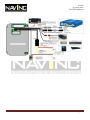
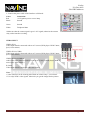
NavInc
P.O. Box 4063
5604 EB Eindhoven
Installation manual Video interface
Designed for Vectra/Signum systems
Version 1.0.0
Content
1: Features
2: Important information
3: Installation & Safety instructions
4: Scope of Delivery
5: Product features
6: Compatibility
7: Wire diagram
8: Requirements
9: Installation
10: Activation
11: .ote
12: FAQ
13: Adjustment
14: Technical support
15: Warranty
16: Technical data
NavInc
2
3
3
4
4
4
5
7
7
15
15
16
17
18
18
18
Pagina 1
NavInc
P.O. Box 4063
5604 EB Eindhoven
1: FEATURES
1. Input Spec. (MULTI VIDEO INTERFACE)
-. 3 x Video Input (External video source).
-. 1 x REAR CAMERA Input. (Rear camera source)
-. 1 x REAR CAMERA Input S-Video. (Rear camera source)
-. 1 x CID Input (Car system Input)
-. 1 x Opel Input
2. Output Spec.
-. 1 x CID output
3. Power Spec.
- Input Power : 8VDC ~ 12VDC
- Consumption Power : 12WATT, Max
4. Switch Input mode
- Automatic detection and switching to the video source for rear view camera.- Possible to switch Input
mode with Remote control)
- Automatic detection and switching to main CID image for viewing caller’s name
(Opel Phone car kit)
5: Extra features:
- Configuration for a reverse camera which does not render "the image in the
mirror"
-Image luminosity adjustment
-Down the consumption of the battery while the CID-controller displays the image
or when the CID is turned off.
-Reset function
-Multi-functions push button for selecting and configuring of video sources. Can be
fitted anywhere in the car.
-Car PC serial port for controlling video interface. In this case, the multi-function
push button will be optional.
NavInc
Pagina 2
NavInc
P.O. Box 4063
5604 EB Eindhoven
2: IMPORTA.T I.FORMATIO.
*Installation must be done by a qualified personnel.
* This interface should be used to display fixed menus during your journey, for example the MP3 menu for
DVD upgrades. The driver of the vehicle must never be distracted by moving pictures. In most
countries/states, watching movies whilst driving is prohibited. Therefore, we do not accept any liability for
material damage or personal injury resulting, directly or indirectly, from the installation or the operation of
this TV-free interface.
*Battery power (+12V) to the interface is fused by a value of 5mA.
*Power of the interface must be ignition power +15. The best way to take the power is from the fuse box.
* Use the device only at a +12 volt vehicle electrical system. Make sure to have a proper ground.
* The device should not be set up in direct proximity of heat sources (e. g. power amplifier).
* Please make sure that no objects or liquids can intrude the interior of the device! (Danger of short circuit!)
* Please follow all caution advises contained in the mounting guidelines.
* Please read through all safety instructions and handling directions intently before installation and start up
of the device.
*Check alway the compatibility of the interface for your car before installation. You can check the
compatibility on www.navinc.nl or call .avInc for support.
3: I.STALLATIO. & SAFETY I.STRUCTIO.S
* Before starting any installation work , you must wait 90 seconds after turning the ignition
switch to the LOCK position and disconnecting the negative (-) terminal from the battery.
When disconnecting the battery, the saved addresses and radio stations of the
navigation system will not be deleted, just the settings of board computer (BC1 and
BC2) will be lost.
NavInc
Pagina 3
NavInc
P.O. Box 4063
5604 EB Eindhoven
4: SCOPE OF DELIVERY
Package:
-Power / Input cable: 1x
-Switch: 1x
-Flat cable: 1x
-Sub-board1: 1x
-Serial cable: 1x
-3 screws: 3x
-Installation instructions: 1x
5: PRODUCT DESCRIPTIO.
Video interface Opel
This interface is used for Opel navigation systems. The interface alloy you to connect video sources to the
navigation screen.
Input Specificities:
- 1 x S-Video input
- 1 x Rear camera input
- 2x V (NTSC) Input.
6: COMPATIBILITY
6.1 Car models
The interface is compatible for Opel navigation system.
Please check www.navinc.nl for more details
6.2 .avigation system:
The interface is compatible for the Opel navigation systems.
-CD30
-CD30 MP3
-CD50
-CD50 phono
-CD70navi
-DVD90
-DVD100
-CDC40 Opera
Please check www.navinc.nl for more details.
NavInc
Pagina 4
NavInc
P.O. Box 4063
5604 EB Eindhoven
7: WIRE DIAGRAM
Power cable
Wires
White
Green
Definition:
Telephone mute
Ground
● Red
● Grey
Camera (+12V)
Camera Ground
A/V cable
AV input
Yellow cinch
Black cinch
Definition:
Video input one
Video input two CVBS
S-Video
Video input
R-CAM white cinch
Camera input rear (NTSC)
Control Port
Not in use
Switch
Switch
Red/Black connector
Definition:
Interface connector
White
Brown
+5V / +12V Backlight
Ground
NavInc
Pagina 5
NavInc
P.O. Box 4063
5604 EB Eindhoven
NavInc
Pagina 6
NavInc
P.O. Box 4063
5604 EB Eindhoven
8: REQUIREME.TS
1: Check if the interface is compatible with you system.
2: When you receive this package you have to check whether there’s
any parts not included and you have to contact us right away.
3: Get the right installation tools
9: I.STALATIO.
* Please read through all instructions and handling directions intently before installation and start up of the
device.
*The interface must be installed inside the CID between the LCD and Controller.
*Turn ignition OFF and wait a couple of minutes before installation
Attention; do not install the interface when the ignition is O..
1: Use OEM unlocktools (optional) to take out the radio unit.
2: Remove the airco unit.
3: Remove the center console. Start with the 4-torkx srews.
NavInc
Pagina 7
NavInc
P.O. Box 4063
5604 EB Eindhoven
4: Pull the center console back warts. The console is locked with 4 lockers.
5: Dissemble the 2 torx screws of the CID. Disample the screen.
6: Pull out the plastic frame
7: Take off the screen. Unscrew the 4 torx srews.
NavInc
Pagina 8
NavInc
P.O. Box 4063
5604 EB Eindhoven
8: After that, open the CID by unscrewed and taking off the four Torx-screws
on the rear shielding plate
The following work must be done with special care not to destroy the CID! You
should discharge yourself from electrostatic energy by touching e.g. the water pipe
prior to open the CID. Also you should not wear clothes that support charging with
electrostatic energy like wool pullovers etc.
9: After removing the rear shield plate of the CID you can see the
CID-controller board and the 30-pole jumper cable that connects the
CID-TFT and CID-controller. It has to be spitted.
10: Next step is to take out the CID-controller boards and CID-TFT. In
order to do that you must first unplug the power connector for the TFTdisplay bellow (Yellow arrow) and flip the controller board by 180° to
the top (red arrow).
NavInc
Pagina 9
NavInc
P.O. Box 4063
5604 EB Eindhoven
11: Now you have to remove the CID-TFT by clicking it out from the
3 clamps marked with the red arrows.
12: View and flip it carefully as indicated in the picture. After that you can see
the 30-pole jumper cable connected to the TFT-display.
13: Now you have to pull out the 30-pole jumper cable connected to the TFT-display
by pushing the white slider of the connector away from the connector in parallel to
unlock the jumper cable (red arrows)
This can be done with the fingertips of both hands. Then the original jumper
cable can be pulled out of the connector with no force.
After that you can move to installation steps.
14: The new jumper cable from the Opel interface kit must be pushed into
this connector and locked with the white slider by pushing it towards the
connector.
It is absolutely necessary to insert the new jumper cable into the
connector in parallel until the end of its travel. It must not be skewed,
otherwise it might cause a short and destroy the CID!
The CID-TFT can be inserted again and the new jumper cable must be
putted through the holes of the shielding plate as shown in the picture.
Because the new jumper cable is too long, it must be folded as shown in the picture.
It does not harm the jumper cable if it is folded. The free end of the jumper cable should near to the top of
plastic frame approx. 3-4 cm in vertical position. The free end of the jumper cable (approx. 1cm) can now
be bended by 90° to horizontal position.
NavInc
Pagina 10
NavInc
P.O. Box 4063
5604 EB Eindhoven
15: Next step, the controller board of the CID can be inserted again. The
original jumper cable that is still connected to the controller board must also
be folded as shown in the picture (yellow arrow) to bring the open end
directly bellow the end if the new jumper wire coming from the TFTdisplay. After folding the original jumper wire of the controller board, you
should verify if it still sits properly inside the connector and if it is not
skewed.
16: Before installing the CID interface board, isolation must be prepared
over capacitors indicated in the picture with red line in order to avoid
contact between the CID Interface board and the CID controller board,
otherwise a short might damage or destroy the CID during operation.
17: Take the CID interface board from kit and put it over CID-controller
board. Both jumper cables must be connected to the connectors of the CIDInterface: the TFT jumper cable to K2 LCD connector, the controller board
cable to K1 CID connector
The jumper cables must not cross themselves or be swapped by 180°! Both
connectors do have a locking slider that must be pushed out first before
inserting a jumper cable. When inserting the jumper cables into the connectors, take care that they are not skewed
and fully inserted! Then push the slider back towards the connector to lock it. The slider might not be locked
properly in the middle, so it is recommended to push the middle of the slider with a small screwdriver towards the
connector to assure proper locking.
NavInc
Pagina 11
NavInc
P.O. Box 4063
5604 EB Eindhoven
18: If this is done, put on the rear shielding plate carefully without moving the
CIDInterface out of its position. Now, insert both special screws from kit into
CID-board holes and under interface board holes using a tweezers as indicated
in the picture.
19: After that, you have to screw them until the rear shielded plate is fixed.
Insert the torx-screws through both interface holes and screw them into special
screws in order to fix the interface to the CID. See picture.
20: You have to do the same with the left corner. After that, screw the other
two torx screws to the opposite holes of rear shielding plate.
21: Don’t forget to attach “green wire” to the torx-screw as indicated in
Figure 17 Attached Cables for proper ground isolation.
22: The interface male connector is indicated with yellow arrows in the
picture.
NavInc
Pagina 12
NavInc
P.O. Box 4063
5604 EB Eindhoven
23: Connect the 12-pins and 6-pins
interface connector to the interface sub
board.
Note:
Make sure that the arrows on the
connector are positioned right.
BUTTO.:
The best position is near to cigarette lighter, but it can be fitted
any ware in dash. After that, you can wire the backlight of button
to the power supply of ashtray LED. Probably, you have to cut and
reconnect again the wires of push button during installation.
Color:
White
Brown
Connection:
+5V or +12V ignition from backlight
Ground
*Connect the black data plug with the interface cable.
NavInc
Pagina 13
NavInc
P.O. Box 4063
5604 EB Eindhoven
POWER SUPLY:
1: Connect the power cable of the interface as followed:
Color:
Red
Black
Connection:
+12V ignition power reverse lamp
Ground
Green
Ground
White
Telephone Mute
*Make sure that the camera signal is good +12V signal, otherwise the camera
relay on the interface is ticking.
VIDEO-I.PUT
VIDEO IN #1
Video input must be connected with an A/V source (DVD player. DVB-T tuner,
Ipod, front camera.)
VIDEO IN #2 (CVBS)
Video input must be connected with an A/V source (DVD player. DVB-T tuner,
Ipod, front camera.)
VIDEO IN #2 (S-VIDEO)
Audio/video input must be connected with an A/V source (DVD player. DVB-T
tuner, Ipod, front camera.)
R-CAM:
Video input must be connected with a rear camera.
.ote:
* Video interface can be working stand alone to connect only a rear camera.
* Use onlye NTSC video signals. Otherwise you get the image like the picture.
NavInc
Pagina 14
NavInc
P.O. Box 4063
5604 EB Eindhoven
10: ACTIVATIO.
Standard Control Functions
The video interface is controlled by the available push button. It main function is to select for displaying
the auxiliary video sources and CID one by one as follow:
1: At start-up the interface will display the main CID information
2: Select Video Input #1 – press the button short time when on the TFT is
displaying the main CID information
3: Select Video Input #2 (CVBS) – press the button short time when on the
TFT is displaying the video input #1.
4: Select CID - press the button short time when on the TFT is displaying the
video source #2.
11: .OTE
In order to execute the first test run, you need to connect the car battery again. When switching on the ignition, the
usual Opel-logo etc. should appear in the CID. Pay special attention to the colors of the CID-display, they must not
be strange or missing. Press and release shortly the push button in order to switch the CID to display the 1st video
input. Press again and select the 2nd video input, and again to come back to the CID display.
If this test looks OK, the CID-Interface with its jumper cables seems to be installed correctly and the battery must
be disconnected again to continue the installation. If you should not see any picture in the CID even after switching
on the ignition or the colors are not displayed correctly or the selected video input are not displayed, the
CID has to be removed again for rechecking. Please refer to chapter FAQ.
NavInc
Pagina 15
NavInc
P.O. Box 4063
5604 EB Eindhoven
12: FAQ
1. Usual CID screen has strange colors or no image what can I do?
-. Probably the jumper cables are not inserted properly. Remove the jumper cables from K1 CID and K2 LCD and
insert them again carefully.
-. Probably one of the color signals (red, green or blue) is not arriving at the TFT-display. Remove the CIDInterface board from the CID and examine the solder pads of the FCCconnectors (30-pole) K1 and K2, especially
the pins 4-7. In case of a bad joint try to resolder the particular pad.
2. The push button is not switching the external video sources
-. The interface male connector was not inserted properly or in the right position. Check the position and re-insert
it.
3. External video screen has strange colors or no image?
-. Probably the TFT jumper cables are not inserted properly. Remove the jumper cable from K2 LCD and insert
them again carefully.
4. External video screen is white/black
-. Your video device is configured to PAL TV system. In this case go to the setup menu of the video device and
select NTSC TV system. Otherwise, you have to replace the video device.
5. The video interface is not switching properly the main CID and external video screens (push button,
rear view camera, Telmute)
-. Try to reset the interface as indicated in Section Video
Interface Control Functions.
- Check the wiring of Rear view camera and Telmute signals.
6. The video interface is switching the external video screen, but back screen is showing.
-. The back screen has a horizontal thin white line, which means no signal is presented at the selected video input.
Check the video out signal (NTSC) of the device with your home TV-LCD or TV.
NavInc
Pagina 16
NavInc
P.O. Box 4063
5604 EB Eindhoven
13: AJUSTME.T
In addition of selecting the video input sources, the push button can be used also for controlling the interface and
the screen as follow:
Control brightness
Increase the brightness by pressing the button longer than 2s when on the screen is displaying one of the two video
input sources. There are available 5 levels (0 to 4). The default value is 2. After level 4, the brightness will go back
to level 0. The value will be kept also after ignition is turned off.
Reset interface
Press the button longer than 2 seconds when on the screen is displaying CID information. The reset is not visible
for the user. After reset, the brightness level is set to the default value (2).
Mirroring the image
Press the button longer than 2seconds while the screen is displaying the video signal from rear view camera.
NavInc
Pagina 17
NavInc
P.O. Box 4063
5604 EB Eindhoven
14: TECH.ICAL SUPPORT
All our products are manufactured under strict quality control. Each device is being tested before
shipment. If nevertheless do occur problems or if you have technical questions, contact us directly under:
Distribution by:
Technical support email:
Technical support tel:
.avInc
[email protected]
0031 (0)40 7511912
In addition to constant product update and development related changes the instruction manuals of the
devices are constantly edited and kept up to date.
To enable us to provide you with the right information and support for the device you have got at hand
please add the following information to every inquiry:
Date of purchase, your name and address, item number and the type of your vehicle.
15: WARRA.TY
The product is designed for automotive use and his environment. The warranty of the product is one year.
No warranty:
• not break the labels attached on the board.
• Damaged of the interface
• Own reperations
• Modified cables
15: TECH.ICAL DATA
Software version:
R2.1
Voltage supply:
12V DC and 24VDC
Voltage-operating capacity:
8 – 24 V
Standby current:
0 mA
Operating current:
12 W
Power input:
12 W
Temperature range:
- 30°C up to + 80°C
Weight:
250g
Dimensions W x H x D:
13 x 50 mm
NavInc
Pagina 18