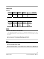
1
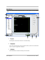
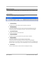
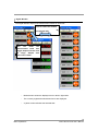
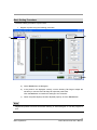
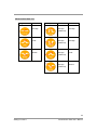
Smart Monitor ZG2
User’s Manual
Smart Sensors
ZG2 Series 2D Profile Measuring Sensors
CONTENTS
SMART MONITOR ZG2 USER’S MANUAL.....................1
SECTION 1 PREPARATIONS .....................................2
Installing the Smart Monitor ZG2 on a Computer .................................................................. 2
Installing the USB Driver......................................................................................................... 3
Uninstalling the Smart Monitor ZG2 ....................................................................................... 3
SECTION 2 BASIC OPERATIONS ................................4
Starting and Quitting ............................................................................................................... 4
Main Window............................................................................................................................. 7
Window Functions..................................................................................................................... 9
Basic Setting Procedure ...........................................................................................................11
SECTION 3 SETTING FUNCTIONS ............................ 15
Selecting Functions ................................................................................................................. 15
Registering Profiles: Profile .................................................................................................... 16
Position Correction: Positioning ............................................................................................. 20
Slope Correction: Slope ........................................................................................................... 21
Setting Measurement Items: Item Setting............................................................................. 22
Checking Measurement Status: Run...................................................................................... 28
System Settings: System......................................................................................................... 30
Data Logging ........................................................................................................................... 35
Profile Logging ........................................................................................................................ 40
Menu Bar Functions ............................................................................................................... 43
SECTION 4 TROUBLESHOOTING ............................. 44
Smart Sensors
ZG2 Series 2D Profile Measuring Sensors
Section 1 Preparations
This section provides information required before using the Smart Monitor ZG2.
Installing the Smart Monitor ZG2 on a Computer
Use the following procedure to install the Smart Monitor ZG2 on a computer. You must be
logged in as a user with administrator rights to install the Smart Monitor ZG2 on Windows 2000
or XP.
1.
Insert the Smart Monitor ZG2 CD-ROM into the CD-ROM drive on your computer.
2.
The Install Wizard will be displayed automatically.
Double-click the Setup.exe file in the CD-ROM if installation does not start
automatically.
3.
Follow the instructions provided by the Install Wizard to install the Smart Monitor
ZG2.
By default, the Smart Monitor ZG2 program is installed in the following directory:
C:\Program Files\OMRON\Smart Monitor ZG2.
Smart Monitor ZG2 help is displayed using Acrobat Reader from Adobe Systems Inc.
If Acrobat Reader has not been installed on your computer; install Acrobat Reader 9.0 from
the Smart Monitor ZG2 CD-ROM.
2
Preparations
Smart Monitor ZG2 User’s Manual
Installing the USB Driver
Use the following procedure to install the USB driver after you install the Smart Monitor ZG2.
The USB driver must be installed only once. The driver will be automatically detected the next
time the Sensor Controller is connected.
1.
Connect the Sensor Controller to the computer using a USB cable.
The Windows toolbar will show that new hardware has been detected and the New
Hardware Detected Wizard will be displayed.
2.
Click the Next Button.
3.
Select the Search optimum driver for disk (recommended) option, and click the Next
Button.
4.
Select the CD-ROM drive checkbox, and click the Next Button.
5.
Make sure that the optimum driver has been detected, and click the Next Button.
6.
The driver installation will start and a completion message will be displayed when the
installation has been completed.Click the End Button.
7.
The same window as displayed in step 1 will be displayed again. Repeat the above
procedure starting from step 2. This completes installation of the USB driver.
Uninstalling the Smart Monitor ZG2
The following procedure can be used to uninstall the Smart Monitor ZG2 from a computer. You
must be logged in as a user with administrator rights to uninstall the Smart Monitor ZG2 from
Windows 2000 or XP.
1.
Select Start – Settings – Control Panel from the Windows menus to open the
Control Panel.
2.
Click the Add/Remove Program Icon in the Control Panel.
3.
Select Smart Monitor ZG2 and click the Remove Button. The Smart Monitor ZG2 will
be uninstalled.
3
Preparations
Smart Monitor ZG2 User’s Manual
Section 2 Basic Operations
This section describes basic operations for the Smart Monitor ZG2.
Starting and Quitting
The procedures to start and quit the Smart Monitor ZG2 are described below.
Starting
Use the following procedure to start the Smart Monitor ZG2.
1.
Be sure that the Controller is operating in Run Mode.
2.
Click the Windows Start Button and select Programs – OMRON – Smart Monitor
ZG2.
3.
Click the [Smart Monitor ZG2] and the program will be started. If this is the first time
that the Smart Monitor ZG2 has been started, the initial window will be displayed.
4.
Select the COM. set Button, and set the USB COM port.
When the Smart Monitor ZG2 has started, settings will be synchronized between the Controller
and computer.
If the Controller is not connected, the Smart Monitor ZG2 can be started in Offline Mode by
selecting the Offline Button.
Do not disconnect the USB cable while the Smart Monitor ZG2 is running.
Do not change the display on the Controller while the Smart Monitor ZG2 is running.
Exit the Smart Monitor ZG2 before turning OFF the power of the Controller.
4
Basic Operations
Smart Monitor ZG2 User’s Manual
When two Controllers are connected, channel numbers are assigned from left CH1, CH2.
Connect a USB cable with PC to the CH2 Controller. We call a left-side Controller the CH1
Controller and a right-side Controller the CH2 Controller.
5
Basic Operations
Smart Monitor ZG2 User’s Manual
Quitting
Use the following procedure to quit the Smart Monitor ZG2.
1.
Select File - Exit from the menus.
2.
To save the settings to the Controller, click the OK Button.
6
Basic Operations
Smart Monitor ZG2 User’s Manual
Main Window
This section describes the part names and functions of the main window of the Smart Monitor
ZG2.
9
7
8
2
1
NEAR
CENTER
FAR
6
5
1.
4
3
Navigator
The Navigator is used to select functions or Controller setting.
2.
Setting Pane
This is the main pane used to set the Controller. Either a profile of the measurement
object or a graph of logged data is displayed.
3.
Set Button
Click the Set Button to transfer the settings to the Controller.
7
Basic Operations
Smart Monitor ZG2 User’s Manual
4.
Save to Controller Button
Click the Save to Controller Button to save the settings to flash memory in the Controller.
If you turn OFF the power without saving the settings, the settings will be cleared.
5.
BUSY Indicator
The BUSY Indicator is lit during communications between the Smart Monitor ZG2 and
the Controller.
6.
Digital ON/OFF Button and Action ON/OFF Button
These buttons are used to open and close window functions.
7.
FullDiaplay ON Button
Click the button to change the display size of the profile.
8.
2CH Display Button
When two Controllers are connected, the profile of CH1 is displayed on the left section
of the window and the profile of CH2 is displayed on the right section.
9.
Menu Bar
The menu bar is used to access menu items used to operate the Smart Monitor ZG2.
8
Basic Operations
Smart Monitor ZG2 User’s Manual
Window Functions
The Action Window and Digital Window can be positioned anywhere on the computer screen.
Action Window
The Action Window contains commonly used function.
1.
CH Select Button
This button is for CH No. selection of the Controller you would use.
2.
Start/Stop Button
If the profile is displayed, this button is used to start and stop displaying the profile.
If measurement data is being logged, this button is used to start and stop logging.
3.
Zero ON/OFF Button
This button executes the zero reset function.
4.
Save Profile Button
This button is used to save a profile of 631 points of data in a CSV file.
5.
Magnifier Button
If the profile is displayed, this button enlarges the profile display.
If measurement data is being logged, this button enlarges the log data graph.
Click this button once and then use the cursor to specify the area to be enlarged. Click
the button again to set the region. Click the Reset Button to return to the default display
6.
Task Buttons
Click one of these buttons to select the task to be displayed for setting.
9
Basic Operations
Smart Monitor ZG2 User’s Manual
Digital Window
The Digital Window displays the measurement values for each task.
Press to switch the number
of displayed task
You
can
make
the
measurement value size
bigger, button with the click
of ‘Large’. Smaller with
the click of ‘Small’ .
・ Measurement values are displayed for four tasks / eight tasks.
・ The currently registered measurement items are displayed.
・ A yellow outline indicates the selected task.
10
Basic Operations
Smart Monitor ZG2 User’s Manual
Basic Setting Procedure
The basic setting procedure is given below.
1.
Register a profile using the following procedure.
b
a
c
b
a)
Select Profile from the Navigator.
b)
If the profile is not displayed correctly, use the Sensing Tab Page to adjust the
sensitivity or use the Filter Tab Page to adjust the profile filter.
Click the Set Button to transfer the settings to the Controller.
c)
When the profile display has been adjusted properly, click the Teach Button.
Registered profiles are saved until either teaching is executed again or until the program is
quit.
11
Basic Operations
Smart Monitor ZG2 User’s Manual
2.
Set the measurement items using the following procedure.
b
a
c
a)
Select Item Setting from the Navigator.
b)
Select the task in the Action Window.
c)
Select the item from the item list, and then click the Set Button.
12
Basic Operations
Smart Monitor ZG2 User’s Manual
3.
Set the measurement region using the following procedure.
a
d
b
c
a)
Click the Setting Tab.
b)
Click the Auto Setting Button.
c)
Specify the desired measurement region with the cursor and then click the Set
Button. The measurement region will be automatically set.
d)
If the results of automatic setting are not correct, adjust the region for each
individual measurement point.
13
Basic Operations
Smart Monitor ZG2 User’s Manual
Refer to the Controller manual for information on the measurement region setting images.
4.
Check measurement status using the following procedure.
b
a
c
d
c
d
c
a)
Select Run from the Navigator.
b)
Select the task to display the measurement point from the Action Window.
c)
A red cursor will indicate the measurement point of the selected task int the Action
Window on the profile.
Confirm that correct measurements are possible using the measurement values
displayed in the Digital Window.
d)
A white cursor indicates the measurement point of task which is not selected in the
Action Window.
14
Basic Operations
Smart Monitor ZG2 User’s Manual
Section 3 Setting Functions
This section describes setting the functions of the Smart Monitor ZG2 that are provided in the
Navigator.
Selecting Functions
Functions and settings are selected from the Navigator.
Name
Function
Bank 1
Bank 1 Settings
Profile
Used to register a profile.
Positioning
Used to correct positioning.
Item Setting
Used to set measurement items.
Run
Use to check measurement
status.
Bank 2
…
Bank 2 Settings
…
Bank 16
Bank 16 Settings
System
I/O and System Settings
Data Logging
Data Logging Function
15
Setting Functions
Smart Monitor ZG2 User’s Manual
Registering Profiles: Profile
Click the Teach Button to register the profile of current measurement object. The Positioning
and Item Setting functions in the Navigator can be used only after a profile has been registered.
Registered profiles are saved until either teaching is executed again or until the Smart Monitor
ZG2 is quit.
Adjusting Sensitivity: Sensing
The Sensing Tab Page is used to adjust the sensitivity.
High-power
You can make the laser emission power stronger with the click of High-power button.
Object
The Object is used to select the method of make profile.
MAX PEAK:
Standard mode
1ST PEAK:
Select this mode when measuaring the 1st surface of the object.
Sensitivity
The Sensitivity Box is used to select the method used to adjustment the sensitivity.
The following methods are supported.
Multi:
Measurement is performed with the sensitivity adjusted for each line in the
measurement region.
Auto:
Measurement is performed with the sensitivity adjusted automatically based on
the sensitivity information in the measurement region.
The selected sensitivity level is displayed on-screen.
Fixed LV:
Measurement is performed with a certain sensitivity level.
HSMulti:
You can make measurement of sensitivity for each 1 line in the measurement area
16
Setting Functions
Smart Monitor ZG2 User’s Manual
with shorter measurement time than ‘Multi’.
Search Button
If the Search Button is clicked, the upper and lower limits will be set automatically to
match the measurement object for Multi Mode.
Upper Limit/Lower Limit
The sensitivity adjustment limits can be set for Multi Mode and Auto Mode.
Upper Limit: Sets the sensitivity adjustment upper limit (maximum value: LV440).
Lower Limit: Sets the sensitivity adjustment lower limit (minimum value: LV1).
Fixed LV (Level)
The Fixed LV Box is used to set a fixed sensitivity level.
Multi.LV Interval
The Multi.LV Interval Box is used to set the sensitivity adjustment interval for Multi Mode.
Fine: LV5 increments (64 steps)
Normal: LV10 increments (32 steps)
HI-Speed: LV20 increments(16 steps)
Setting the Measurement Region
Region
The accuracy of sensitivity adjustment can be improved by restricting measurement to
only a specified measurement region. Use cursor to set the region.
Set: Transfers settings to Controller.
Reset: Resets the region.
Return: Ends setting the region.
Teaching
Teach Button
Click the Teach Button to register the profile.
17
Setting Functions
Smart Monitor ZG2 User’s Manual
Profile Filters: Filter Tab Page
Use the Filter Tab Page to set a filter for the profile.
APS
APS can automatically set the parameters to measure the profile.
Averaging
Changes in data can be smoothed out using the average values of adjacent data.
Averaging is performed in the width direction
Smoothing
Changes in data can be smoothed out using the intermediate values of adjacent data.
Smoothing is performed in the width direction.
Interpolation
Interpolation is used to interpolate between data in areas while profile data is missing
(areas where measurement is not possible).
OFF:
A measurement error signal will be output for each area where measurement cannot
be obtained.
ON:
Data for areas where measurements could not be obtained is calculated using linear
interpolation between the data to the left and right. (Up to 64 missing data values can
be obtained with this method.)
Pixel Number
Set the number of pixels to be interpolated when interpolating profile data.
Noise removal
Other than images with a setting pixel will be regarded as noise and exduded from
measurement.
18
Setting Functions
Smart Monitor ZG2 User’s Manual
GAIN
You can set the CMOS gain , can be measured stably.
Level1 (gain small) Æ Level7 (gain large)
BG thresholdLV
You can set the threshold value you want to ignore as noise in the image.
19
Setting Functions
Smart Monitor ZG2 User’s Manual
Position Correction: Positioning
Positioning can be corrected by setting a reference position and correction direction to shift the
position of the measurement object.
Positioning
The Positioning Box is used to select the method for position correction.
OFF: The position is not corrected.
Height: Correction is performed in the height (Z) direction.
Position: Correction is performed in the position (X) direction.
Height+Position: Correction is performed in both the height and position directions.
Base Start/Base End
Set the start and end lines for the region to use to measure the amount of position shift.
Base Start: Sets start line.
Base End: Sets end line.
Point
Select the measurement point to be used as a reference.
Average: Measures the average value inside the region.
Peak: Measures the peak value inside the region.
Bottom: Measures the bottom value inside the region.
Edge LV (Level)
Set the edge level. To correct shift in the position direction, use the point of intersection of
the profile and the edge level as an edge.
Direction
Set the direction in which to search for edges.
L to R: A search is made for the 1st edge from the left in the region.
R to L: A search is made for the 1st edge from the right in the region.
20
Setting Functions
Smart Monitor ZG2 User’s Manual
Slope Correction: Slope
Slope of the measurement object can be corrected by setting a reference position.
Slope
Set whether or not to perform slope correction.
OFF: The slope is not corrected.
ON : The slope is corrected.
Precision
Set whether or not to perform slope correction at high precision.
OFF: The normal correction is performed.
ON : The slope is corrected at high precision.
Base Start/Base End
Set the start and end lines for the region to use to measure the slope.
P1(P2) Start: Sets start line.
P1(P2) End: Sets end line.
P1(P2)
Select the measurement point to be used as a reference.
Average: Measures the average value inside the region.
Peak: Measures the peak value inside the region.
Bottom: Measures the bottom value inside the region.
21
Setting Functions
Smart Monitor ZG2 User’s Manual
Setting Measurement Items: Item Setting
There are eighteen measurement items. A measurement item can be set for each task so that
up to four measurements can be performed simultaneously.
Selecting a Measurement Item: Item Tag Page
Select a measurement item in the Item Tab Page using the cursor.
Set Button: Registers the selected measurement item.
Delete Button: Deletes the selected measurement item.
Setting Measurements: Setting Tab Page
The Setting Tab Page is used to set the region and features.
Auto Setting Button
Click the Auto Setting Button to automatically set the measurement region simply by
enclosing the desired area by using the cursor.
Set: Transfers the region to the Controller.
Reset: Resets region.
Return: Ends Auto Setting Mode.
Manual Setting
The target region can be set manually when it is not set automatically. Set the
measurement region manually when using the angle or cross-sectional area
measurement items. Automatic setting is not possible for these items. Use the cursor or
input the values numerically.
Display Tab Page: Used to set the region or edge level.
Details Tab Page: Used to select the measurement point or the edge search direction.
22
Setting Functions
Smart Monitor ZG2 User’s Manual
Measurement Item List
P1 Point
Height
P1
P1
Average
Peak
2-pt step
P1
P2
P1
P2
P2
Bottom
P1
P1
P1
P2
P1 Point
P2 Point
Average
(reference)
Average
Average
(reference)
Average
Average
(reference)
Peak
Average
(reference)
Bottom
23
Setting Functions
Smart Monitor ZG2 User’s Manual
3-pt step
P1
P3
P1 Point
P2 Point
P3 Point
Average
(reference A)
Average
(reference B)
Average
Average
(reference A)
Average
(reference B)
Average
Average
(reference A)
Average
(reference B)
Peak
Average
(reference A)
Average
(reference B)
Bottom
P2
P3
P1
P2
P1 P2
P3
P2
P1
P3
Edge Position
P1
P1 Direction
L to R
P1
R to L
Edge width
P1
P2
P1
P2
P1 Direction
P2 Direction
L to R
R to L
L to R
R to L
24
Setting Functions
Smart Monitor ZG2 User’s Manual
Cross-sectional
area
Point
None
Angle
P1 Point
P2 Point
P1
Average
(reference)
Average
P1 Point
P2Point
P3 Point
P4 Point
Average
(reference
A)
Average
(reference
A)
Average
(reference
B)
Average
(reference
B)
P1 Point
P2Point
P3 Point
P4 Point
Average
(reference
A)
Average
(reference
A)
Average
(reference
B)
Average
(reference
B)
P2
Angle2
P1
P2
P3 P4
Corner
P2
P1
P3
P4
25
Setting Functions
Smart Monitor ZG2 User’s Manual
Calculation
K
m/n
X/Y
Select the task.
Offset value
−999.99999
to 999.99999
Span Value
−10.0 to
+10.0
(Only a task number smaller than
the task number for which the
calculation is set can be selected.)
K + mX + nY
26
Setting Functions
Smart Monitor ZG2 User’s Manual
Scaling
Scaling can be set to adjust for differences between measurement values and actual sizes.
Scaling can be set for each registered measurement item. Do not use scaling for the
Calculation measurement item.
1.
Scaling is enabled by setting the Scaling Mode Box to ON.
2.
Select either Auto or Manual in the Scaling Type Box.
Automatic Setting for One-point Scaling
With one-point scaling, one measurement is performed to set the correction for the
measurement value. One-point scaling is suitable for the following measurement items:
2-pt step, 3-pt step, and edge width.
Place the measurement object in the measurement region.
Input the correction for the measurement value, and click the Set Button.
Automatic Setting for Two-point Scaling
With two-point scaling, measurements are performed at two positions to set the
corrections for the measurement values. Two-point scaling is suitable for the following
measurement items: height and edge position.
a)
Place the measurement object in the measurement region.
Input the correction for the first measurement value, and click the Set Button.
b)
Move the measurement object, and
Input the correction for the second measurement value, and click the Set Button.
Manual Scaling
Manual scaling can be used to numerically input the span and offset to fine-tune
measurement values. Manual scaling must be used for the cross-sectional area and angle
measurement items.
Span
Set the slope of the sensor characteristics as a coefficient.
Setting range: −4.0 to 4.0
Offset
Set a fixed value to add to or subtract from the measured value.
Setting range: −999.99999 to +999.99999
27
Setting Functions
Smart Monitor ZG2 User’s Manual
Checking Measurement Status: Run
Measurements can be checked by displaying a red point to indicate the measurement point on
the profile. Select the task to display from the Action Window.
Measurement Filter: Filter Tab Page
A filter can be set for measurement values.
Averaging
The average of a set number of measurements can be output as the measurement result.
Median Filter
The median value of the measurements can be output as the measurement value.
Processing during Non-measurement: Keep/Clamp
The output method to use when measurements are not being performed can be set.
Keep: The status immediately before measurement is stopped is held and output.
Clamp: The preset clamp value (error value) is output.
Hold
You can set hold conditions of measurement value. The hold function is to hold a certain
value in the sampling time.
Off: The hold is not performed.
Peak: The peak value of the measurement values are held in the sampling interval.
Bottom: The bottom value of the measurement values are held in the sampling interval.
P-P: The difference between the peak value and the bottom value are held.
Average: The average value of the measurement values are held in the sampling.
Sample: The sample value of the measurement values are held in the sampling.
Setting the Judgment Value and Offset: Judgment
The threshold value and offset (zero value) to use for judgment can be set for each task.
Judgment Threshold Values: High/Low
Set the range of measurement values to be judged as OK.
High: Sets the high threshold value.
Low: Sets the low threshold value.
28
Setting Functions
Smart Monitor ZG2 User’s Manual
Offset Value: Zero
An offset can be set to use a value other than 0 as the reference value when resetting.
29
Setting Functions
Smart Monitor ZG2 User’s Manual
System Settings: System
The System Setting is used to setting I/O and system settings for the Controller.
Analog Output Setting: I/O
The analog output from the Controller can be set.
Task
Select the task to output.
Clamp Level
A present clamp value (error value) can be output when the light density is temporarily
excessive or insufficient. Set the clamp value here.
Analog Scaling
The relationship between the displayed measured value and the output value can be set.
1.
Set the Scaling Mode Box to ON.
2.
Input the measurement value corresponding to the minimum output.
3.
Input the measurement value corresponding to the maximum output,
4.
Click the Set Button.
Correcting Analog Output Values
Discrepancies may occur between the analog output values from the Controller and the
actual measured values. The analog output can be corrected for this discrepancy.
1.
Set the Correction Box to ON.
2.
Input the correction for the maximum output value, and click the Output Button.
The Controller will output the corrected value while the Output Button is being
clicked.
3.
Adjust the correction value as required.
4.
Repeat steps 2 to 3 to set the correction for the maximum output value.
5.
Click the Set Button.
30
Setting Functions
Smart Monitor ZG2 User’s Manual
Parallel Output Unit Settings: I/O
The ZG-RPD Parallel Output Unit functions can be set.
Output
Set the output from the Parallel Output Unit.
Measure: Outputs the measured value (16-bit binary).
Judge: Outputs the judgment result (High, Pass, Low, or Error).
Task
Set the task to be output. This setting is enabled when the measured value is output.
Digit
Set the number of digits past the decimal point for the measured value.
Judge
If the number of registered task is less than 4, select [4 Tasks].
Otherwise, select [8 Tasks].
I/O Conditions: I/O
The I/O functions of the Controller can be set.
Bank Switching
Set the method to use to switch banks.
Menu: Banks are switched by using the control keys on the Controller.
EXT In: Banks are switched by using the external input lines.
Trigger
Set the measurement timing method.
Gate Time [ms]
Set the period that the gate signal is to remain ON.
Gate Delay [ms]
Set the time delay from when the result is output to when the gate signal is turned ON.
31
Setting Functions
Smart Monitor ZG2 User’s Manual
Head Settings: System
Settings for the Head can be set.
Head Mounting
Set how the Head is installed.
Diffuse: Select Diffuse when the Head is installed for diffuse reflection.
Regular: Select Regular when the Head is installed for regular reflection.
CCD Mode
Set the resolution of the Head’s CCD.
Normal:
Standard measurement is performed.
Hi-Resolution:
Measurement is performed at a resolution of about four times that of standard mode.
Hi-Speed:
Measurement is performed with the number of pixels halved in the height direction.
(Measurement distance becomes roughly 1/2 of the rated distance.)
Load Data
Set the timing when the Head information is transferred to the Controller.
Head:
The data currently saved in the Head is read each time that the Controller is started.
Controller:
Data is not read from the Head when Controller is started if the same Head was
connected at the immediately preceding startup.
Sync
Mutual interference between two Sensor Heads can be prevented by shifting the laser.
OFF:
The mutual interference prevention function is not available .
ON:
The mutual interference prevention function is available.
32
Setting Functions
Smart Monitor ZG2 User’s Manual
Controller Settings: System
The Controller functions can be set.
Decimal Places
Set the number of digits to display past the decimal point in the measurement result. The
number of digits past the decimal point in serial output uses this setting.
Eco Mode
Eco Mode can be set to darken the LCD screen to reduce current consumption when
control keys or selection switches are not operated for three minutes or longer.
Language
Set the language to display on the LCD screen.
Icon Color
You can set the color used to display icons.
Initializing Controller Settings: Initialize
When initialization is performed, the settings in all banks and all system settings will be
initialized regardless of the currently selected bank.
Inclination Correction: Inclination
Click the Teach Button to register the profile.
Head inclination can be corrected by setting a reference position of the profile.
Inclination
Set whether or not to perform inclination correction.
OFF: The inclination is not corrected.
ON : The inclination is corrected.
Base Start/Base End
Set the start and end lines for the region to use to measure the inclination.
P1(P2) Start: Sets start line.
P1(P2) End: Sets end line.
33
Setting Functions
Smart Monitor ZG2 User’s Manual
P1(P2)
Select the measurement point to be used as a reference.
Average: Measures the average value inside the region.
Peak: Measures the peak value inside the region.
Bottom: Measures the bottom value inside the region.
34
Setting Functions
Smart Monitor ZG2 User’s Manual
Data Logging
Data logging can be used to log measurement values for each task.
Logging Condition Settings: Chart Tab Page
Set the logging conditions on the Chart Tab Page.
Stop Condition
Data : Stops data storage when the specified count is reached.
Time: Stops data storage when the specified time has expired (Continuous Mode only).
Y-axis scale
Auto
: Y-axis scale is automatically changed according to measurement value.
35
Setting Functions
Smart Monitor ZG2 User’s Manual
Manual
: Upper / Bottom limit for Y-axis scale can be set by a user.
Starting Logging: Chart Tab Page
The Action Window is used to start and stop data logging.
2, 4
1
3
5
1.
Select the task to display by clicking a Task Button in the Action Window.
2.
Click the Start Button in the Action Window. (If using the trigger has been enabled, the
Counter will wait for the external trigger.)
3.
During logging, a realtime waveform will be displayed.
4.
Logging will stop when the stop condition has been satisfied or the Stop Button is
clicked.
5.
Click the Save Button. The logged data will be output to a CSV file.
36
Setting Functions
Smart Monitor ZG2 User’s Manual
CSV File Format
Continuous:
Column 1
Column 2
Column 3
Column 4
…
Column 10
Number
Time [s]*
Task 1
results
Task 2
results
…
Task 8
results
*Time measured by the computer’s system clock.
Trigger:
Column 1
Column 2
Column 3
…
Column 9
Number
Task 1
results
Task 2
results
…
Task 8
results
Do not run other applications while logging data.
A few milliseconds' variation may occur in the sampling interval in Continuous Mode.
(Depending on the personal computer specifications, it may be 20 ms before stable sampling
can begin.)
Allow at least 50 ms between external trigger inputs in Trigger Mode.
Do not input the trigger to the Controller before starting data logging.
Sampling interval: 20 to 1,000 ms
Maximum storage data capacity: 65,500
Maximum storage time: Approx. 22 min for 20-ms interval or approx. 18 h for 1,000-ms interval
37
Setting Functions
Smart Monitor ZG2 User’s Manual
Analyzing Data: Graph Tab Page
Logged data can be analyzed on the Graph Tab Page.
2
3
1
1.
Click the Load Button to load the data from a CSV file.
2.
Select the task to display by clicking a Task Button in the Action Window.
3.
The graph scale is automatically set, but it can be set numerically if desired.
38
Setting Functions
Smart Monitor ZG2 User’s Manual
Cursors
The measurement value at each cursor and the relative value between the cursors can
be displayed.
Click the Centering Button to move the cursor to the center of the graph.
The graph can be scrolled by dragging the cursor outside the window area.
Free: The free cursor can be moved to any position in the graph as a reference point.
Snap: The snap cursor snaps to the measurement data.
Magnifier
Click the Magnifier Button in the Action Window to enlarge the graph. Specify the area to
enlarge with the cursor. The setting will become effective when the Magnifier Button is
clicked again. Reset the display by clicking the Reset Button.
39
Setting Functions
Smart Monitor ZG2 User’s Manual
Profile Logging
Profile logging can be used to log profiles.
Logging Condition Settings
Set the logging conditions.
Stop Condition
Data : Stops data storage when the specified count is reached.
Time: Stops data storage when the specified time has expired (Continuous Mode only).
Starting Logging
The Action Window is used to start and stop profile logging.
40
Setting Functions
Smart Monitor ZG2 User’s Manual
1, 3
2
4
1.
Click the Start Button in the Action Window. (If using the trigger has been enabled, the
Counter will wait for the external trigger.)
2.
During logging, a realtime profile will be displayed.
3.
Logging will stop when the stop condition has been satisfied or the Stop Button is clicked.
4.
Click the Save Button. The logged profile will be output to a CSV file.
41
Setting Functions
Smart Monitor ZG2 User’s Manual
CSV File Format
Column1
Column2
Column3
Column4
…
Column10
Time1 [s]
Time2 [s]
Time3 [s]
Time4 [s]
…
Time10 [s]
Point 1 of
the profile
Point 1 of
the profile
Point 1 of
the profile
Point 1 of
the profile
…
Point 1 of
the profile
(time1)
(time2)
(time3)
(time4)
Point 2 of
the profile
Point 2 of
the profile
Point 2 of
the profile
Point 2 of
the profile
(time1)
(time2)
(time3)
(time4)
Point 3 of
the profile
Point 3 of
the profile
Point 3 of
the profile
Point 3 of
the profile
(time1)
(time2)
(time3)
(time4)
…
…
…
…
…
…
Point 631 of
the profile
Point 631 of
the profile
Point 631 of
the profile
Point 631 of
the profile
…
Point 631 of
the profile
(time1)
(time2)
(time3)
(time4)
(time10)
…
Point 2 of
the profile
(time10)
…
Point 3 of
the profile
(time10)
(time10)
42
Setting Functions
Smart Monitor ZG2 User’s Manual
Menu Bar Functions
This section describes the functions in menu bar.
Saving and Loading Settings: File
Controller settings can be saved in files on the computer.
Save Settings: Select the folder in which you want to save the file, and enter the file name.
Load Settings: Select the file from which you want to load settings to the Controller.
Capturing Windows: File
The Main Window and Digital Window can be captured and saved as .jpg files.
Capture: Select the folder in which you want to save the file and enter the file name.
Copying and Initializing Banks: Edit
The current bank data can be copied to another bank, and the current bank data can be
initialized.
Copy Bank: Select the source bank and copies to the current bank in the Navigator.
Initialize Bank: The current bank in the Navigator will be initialized.
Selecting the Save Folder: Tools
The folder in which to save data can be selected.
Options: Select the folder in which you want to save files. And click OK.
Help and Version Information: Help
The help file can be opened and ZG information can be displayed.
Help: Displays the help file.
Information: Displays system information about the ZG.
43
Setting Functions
Smart Monitor ZG2 User’s Manual
Section 4 Troubleshooting
Error Messages and Corrective Actions
Error message
Corrective actions
Failed to communicate.
Check the cable connection and port settings.
Set the Controller to Run Mode.
If the communications cable is disconnected by mistake, restart
the Smart Monitor ZG2 and the Controller.
Cannot detect
measurement object.
There is no measurement object.
Place the measurement object inside the measurement range
Cannot detect edge.
Set the Edge Level parameter so that the edge crosses the
profile. Confirm that teaching to register the profile was
executed correctly.
Auto setting failed.
Automatic setting cannot be executed on the current region.
Set the region again referring to the manual.
Scaling failed.
The scaling correction range was exceeded.
Check the input values.
Illegal entry. Set low value
smaller than high value.
Reset the values so that the low value is less than the high
value.
Reset the values so that the minimum value is less than the
Illegal entry.
Set minimum value smaller maximum value.
than maximum value.
Reference
failed.
registration Head inclination is failed.
Check the registered profile and the region to measure the
inclination
Too many calculation.Item The total measured points is more than 32.
cancelled.
44
Troubleshooting
Smart Monitor ZG2 User’s Manual
Revision History
Revision code
Date
Revised content
A
December 2008
Original production
45
Smart Monitor ZG2 User’s Manual