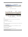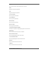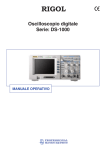
1
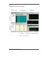
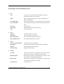
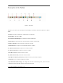
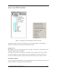
User Manual RIGOL Publication number DS1-010133 May. 2006 UltraScope For DS1000 Series © Copyright Rigol Technologies, Inc. 2006 All Rights Reserved Copyright © RIGOL TECHNOLOGIES, INC. 2006 All Rights Reserved. Rigol products are covered by P.R. China and foreign patents, issued and pending. Information in this publication supercedes that in all previously published material. Specification and price change privileges reserved. NOTE: RIGOL is registered trademark of RIGOL TECHNOLOGIES, INC. Copyright 2006 Rigol Technologies, Inc. UltraScope For DS1000 2 Product Description UltraScope Software introduces a family of Windows 95, 98, 2000, NT, and Windows XP applications that connect your RIGOL DS1000 series oscilloscopes to your PC desktop by USB or RS-232 . The UltraScope software provides the following control and analysis features: z Use Data Browser to display captured waveforms, data and measurements. z Use DSO Controller to control the oscilloscope locally or over the network. z Export the waveform by “BMP” format. z Save the data into “TXT” or “EXCEL” file for analysis. z Print the waveforms. Copyright 2006 Rigol Technologies, Inc. UltraScope For DS1000 3 System Requirements To install and run UltraScope software, you must have an IBM-compatible PC with the following installed: z Microsoft Windows 95, 98, NT 4.0, 2000, or Windows XP z 16 MB RAM or greater recommended z CD-ROM drive, 4X or better z Super VGA monitor or better z 10 MB of disk space z Available RS-232 COM port You must have a DS1000 series oscilloscope and the firmware version must be higher or equal to 01.02.22 . To connect to PC, the oscilloscope must install USB dirver or have an available RS-232 COM port. Copyright 2006 Rigol Technologies, Inc. UltraScope For DS1000 4 Contents This manual is the user guide for the Ultrascope software, and it contains four chapters. Chapter 1: Installation and Uninstallation This chapter guides you install or uninstall the software. Chapter 2: Operating the Ultrascope This chapter introduces how to use Ultrascope software in detail. Chapter 3: Prompting messages and Troubleshooting This chapter gives solutions to frequently encountered problems or failures when testing. And it lists all the system prompting messages and their meanings. Chapter 4: Support & Service This chapter contains service information for Ultrascope. Copyright 2006 Rigol Technologies, Inc. UltraScope For DS1000 5 List PRODUCT DESCRIPTION .....................................................................................................3 SYSTEM REQUIREMENTS ...................................................................................................4 CONTENTS..............................................................................................................................5 CHAPTER 1: INSTALLATION AND UNINSTALLATION...................................................7 CHAPTER 2: OPERATING THE ULTRASCOPE ..................................................................8 Description of the user interface............................................................................................9 Description of the software menu........................................................................................10 Description of the Toolbar...................................................................................................12 How to use DSO Controller.................................................................................................14 Shortcut Menu.....................................................................................................................15 Instant Running Control......................................................................................................16 Use DSO Controller to set up CH1& CH2 .........................................................................17 Use DSO Controller to set up Time Base............................................................................20 Use DSO Controller to set up Trigger System ....................................................................22 Use DSO Controller to set up Acquisition System .............................................................34 Use DSO Controller to set up Display System ...................................................................35 How to use the Virtual Keyboard........................................................................................36 How to use Data Browser ....................................................................................................37 How to display a waveform ................................................................................................39 How to Measure with Data Browser...................................................................................42 How to get waveform data with Data Browser ...................................................................45 General Options ..................................................................................................................52 CHAPTER 3: PROMPTING MESSAGES AND TROUBLESHOOTING ...........................55 Prompting Messages ...........................................................................................................55 Troubleshooting ..................................................................................................................55 CONTACT RIGOL.................................................................................................................56 Copyright 2006 Rigol Technologies, Inc. UltraScope For DS1000 6 Chapter 1: Installation and Uninstallation This section describes how to install Ultrascope software on your computer. Installing Ultrascope Software Follow the steps below to install Ultrascope software. 1. Insert the CD-ROM into the CD-ROM drive. Run the Ultrascope for DS1000 Series.EXE file to start the installation wizard. 2. The Welcome to Ultrascope dialog appears. Read the information in the dialog, and click Next. 3. Select to accept the terms in the License Agreement dialog, and click Next. 4. The Customer Information dialog appears. Read or edit the information in the dialog, and Click Next. 5. Click Install to start installation. After all the files have been installed, the Finish button appears. 6. Click Finish to complete the installation process. Uninstallation To uninstall Ultrascope for DS1000 Series Oscilloscopes, you can click by the follow steps: Start-> Program -> Ultrascope for DS1000 Series->Uninstall. Or use the Add/Remove program in the Microsoft Windows Control Panel . Both uninstall methods activate the Uninstall wizard, which takes you through the uninstall process for Ultrascope. Copyright 2006 Rigol Technologies, Inc. UltraScope For DS1000 7 Chapter 2: Operating the Ultrascope This chapter covers the following topics: Description of the user interface Description of the software menu Description of the Toolbar How to use DSO Controller How to use Data Browser How to use Virtual Keyboard How to set up General Options Copyright 2006 Rigol Technologies, Inc. UltraScope For DS1000 8 Description of the user interface Figure 1: Software interface Copyright 2006 Rigol Technologies, Inc. UltraScope For DS1000 9 Description of the software menu 1. File New: Open: Save Data Sheet: Save Controller: Save All: Page Setup: Exit: To create a new document of Data Sheet, Controller, Waveform, Measure or Wave Data. Opens a dialog box that lets you open a Data Sheet or a DSO Controller file. Saves the Data Sheet to its current directory and file name. Saves the DSO Controller to its current directory and file name. Saves all files Setups page attributes before printing Exits Ultrascope 2. View Toolbar: Status Bar: Show Controller: Show Data Browser: Turns the toolbar on and off Turns the status bar on and off Turns the DSO Controller on and off Turns the Data Browser on and off 3. Tools Connect to Oscilloscope: Disconnect: Options: License Setup: Connects PC to the oscilloscope Disconnects the link between PC and the oscilloscope I/O settings and general settings Register the Ultrascope 4. Window Cascade: Tile Horizontal: Tile Vertical: Arrange Icons: Stacks open windows in a diagonal overlap, starting from the upper left corner of the data browser window. Resizes open windows in the data browser window so that all windows are displayed horizontally. Resizes open windows in the data browser window so that all windows are displayed vertically. To arrange icons Copyright 2006 Rigol Technologies, Inc. UltraScope For DS1000 10 5. Help Contents…: About: Displays the table of contents for the help. Copyright Information Copyright 2006 Rigol Technologies, Inc. UltraScope For DS1000 11 Description of the Toolbar Figure 2: Tool Bar 1( New ): To create a new document of Data Sheet, Controller, Waveform, Measure or Wave Data. 2( Open ): To open a document of Data Sheet or Controller 3( Save All ): To save all files 4( Connect to Oscilloscope ): Connect PC to the oscilloscope 5( Disconnect ): Disconnect the link between PC and the oscilloscope 6( DSO Controller ): Show the DSO Controller window 7( Data Browser ): Open or close the Data Browser window 8( Add New Waveform ): Add new waveform window 9( Add New Measure ): Add new measure window 10( Add New Data ): Add new data window 11( Add New Record ): Add new record window 12( Add New Memory Waveform ): Add new memory waveform window 13( Options ): I/O settings and general settings 14( Connection Status Lamp ): The lamp will turn blue in connecting status, and it will turn red after disconnect the link between PC and Oscilloscope. Copyright 2006 Rigol Technologies, Inc. UltraScope For DS1000 12 Note: After connecting the PC to the oscilloscope, the keys and knobs on the front panel will be locked. To activate the front panel control, you must disconnect the link in Ultrascope software or pressing the FORCE key on the front panel. Copyright 2006 Rigol Technologies, Inc. UltraScope For DS1000 13 How to use DSO Controller Figure 3: The Explorer View and Menu of DSO Controller The DSO Controller consists of an Explorer View and a Shortcut Menu. The following illustration descripts each component of the DSO Controller. Explorer View The Explorer view lists the instrument and its settings, controls, and virtual keyboard in a Windows Explorer-like tree diagram. To display the contents of an Explorer view subtree, click on the plus icon next to an item you want to explore. To close a subtree, click on the minus icon next to the subtree. The lowest-level subtrees generally represent the scope control that you can setup or execute. Download & Upload You could click the Upload button to transfer parameters to your oscilloscope, and you can get these parameters by pressing the Download button. Copyright 2006 Rigol Technologies, Inc. UltraScope For DS1000 14 Shortcut Menu The Shortcut menu contains commands and settings available in DSO Controller. You could access the menu by right-click on an icon. New Control File: Creates a new document for DSO Controller. Open Control File: Opens a dialog box that lets you open a DSO Controller file. Save Control File: Saves the DSO Controller to its current directory and file name. Save Control File As: Opens a dialog box that lets you save a DSO Controller file. Connect To DSO: Connect PC to the oscilloscope. Disconnect: Disconnect the link between PC and the oscilloscope. Upload: Upload the settings and parameters from DSO Controller to the oscilloscope. Download: Download the settings and parameters from the oscilloscope to DSO Controller. Expand All: Expand the Explorer View to display the lowest-level subtrees Copyright 2006 Rigol Technologies, Inc. UltraScope For DS1000 15 Instant Running Control On the DSO Controller panel, the “Running Control” subtree includes four instant action keys. (See Figure 4) Figure 4 Double-click “Run|Stop” to pop up a dialogue box, you could select “RUN” or “STOP” to let the instrument run or stop. Double-click the other three action keys to execute the “Autoset”, “Set Trig to 50%” or “Force Trigger” actions instantly. Copyright 2006 Rigol Technologies, Inc. UltraScope For DS1000 16 Use DSO Controller to set up CH1& CH2 You can set up the parameters of channel 1 or channel 2 at “CH1”, “CH2” subtrees on DSO Controller panel. Figure 5 Double-click the lowest subtrees to pop up a list, you could select a value and set the instrument to use that value. Copyright 2006 Rigol Technologies, Inc. UltraScope For DS1000 17 Table 1: Subtree Display Volt/Div Offset Coupling BW Limit Probe Settings Comments ON OFF Select “ON” to display the channel Select “OFF” to close the channel 2.00mV~ 5.00V -40.00V~+40.00V (Volt/Div> 100mV) -2.00V ~ +2.00V (Volt/Div<200mV) AC DC Select the Volt/Div value within the range of 2.00mV~ 5.00V ON OFF 1X 10X 100X 1000X Limits the bandwidth to reduce display noise. To set “OFF” will get full bandwidth. Select the vertical offset value Set to “AC” coupling Set to “DC” coupling Set this to match your probe attenuation factor to make the vertical scale readout correct Copyright 2006 Rigol Technologies, Inc. UltraScope For DS1000 18 Use DSO Controller to set up LA(Mixed-Signal Oscilloscope) You can set up the parameters of digital channels at “LA” subtrees on DSO Controller panel.. Figure 6 Double-click the lowest subtrees or the second-subtrees to pop up a list, you could select a value and set the instrument to use that value. Table 2: Subtree Second-subtree Settings Comments Dipslay D15-D0 ON OFF Turn on or turn off single channel of D15-D0. Position D15-D0 0-15 Select the vertical position of the channel D15-D0. TTL CMOS ECL User Select style of whole digital channel. The threshold voltage can set by user in user-defined style. Threshold Reset waveform D15-D0. Reset Copyright 2006 Rigol Technologies, Inc. UltraScope For DS1000 of the channel 19 Use DSO Controller to set up Time Base You could set up the horizontal parameters of the oscilloscope at the “Time Base” subtree on DSO Controller panel. When the trigger mode is not Alternative, you can set up the value as below figure and table .(See Figure 7) Figure 7 Table 3: Subtree Settings Time/Div 5ns~50s Delay Format Comments Select the timebase of CH1 from 5ns to 50s Display the delay value Y-T X-Y Roll Select to Y-T format Select to X-Y format Select to Roll format Copyright 2006 Rigol Technologies, Inc. UltraScope For DS1000 20 When the trigger mode is Alternative, you can set up the value as below figure and table. Figure 8 Table 4: Subtree CH1 Second-subtree Time/Div Settings Comments 5ns~50s Select the timebase of CH1 from 5ns to 50s Delay CH2 Time/Div Display the delay value of CH1 5ns~50s Delay Select the timebase of CH2 from 5ns to 50s Display the delay value of CH2 Copyright 2006 Rigol Technologies, Inc. UltraScope For DS1000 21 Use DSO Controller to set up Trigger System You could set up the trigger system of the oscilloscope at the “Trigger” subtree on DSO Controller panel. Figure 9: Edge Trigger Copyright 2006 Rigol Technologies, Inc. UltraScope For DS1000 22 Table 5: Edge Trigger Subtree Method Source Slope Mode Coupling Settings EDGE PULSE VIDEO SLOPE ALTERNATIVE PATTERN DURATION CH1 CH2 EXT EXT5 AC D15-D0 RISING FALLING BOTH AUTO NORMAL SINGLE DC AC HF LF Comments Select trigger mode as “EDGE” Select trigger mode as “PULSE” Select trigger mode as “VIDEO” Select trigger mode as “SLOPE” Select trigger mode as “ALTERNATIVE” Select trigger mode as “PATTERN” Select trigger mode as “DURATION” Select the input source as the trigger signal EXT and EXT5 use the signal applied to the EXT TRIG connector as the source. Select any digital channel in D15-D0 as trigger source (only in mixed-signal oscilloscope). Select to trigger on the rising, falling or both edge of the signal Select the type of triggering Selects the components of the trigger circuitry the trigger signal applied to Level -12.00div to +12.00div Set the trigger level from -12.00div to +12.00div Sensitivit y 0.10div to 1.00div Set the trigger sensitivity from 0.10div to 1.00div Holdoff 100ns ~ 1.5s Select the holdoff time from 100ns to 1.5s Copyright 2006 Rigol Technologies, Inc. UltraScope For DS1000 23 Figure 10: Video Trigger Copyright 2006 Rigol Technologies, Inc. UltraScope For DS1000 24 Table 6: Video Trigger Subtree Settings Comments Source CH1 CH2 EXT EXT5 Polarity POSITIVE NEGATIVE Normal triggers on the negative edge of the sync pulse and inverted triggers on the positive edge of the sync pulse All line Select to trigger on all lines Line num Select to trigger on the specified line Odd Field Select to trigger on odd field Even Field Select to trigger on even field Line number 1 ~ 525/625 Select the trigger line number Video Standard NTSC PAL/SECAM Select the video standard for sync and the number count Level -12.00div to +12.00div Set the trigger level from -12.00div to +12.00div Sensitivity 0.10div to 1.00div Set the trigger sensitivity from 0.10div to 1.00div Holdoff 100ns ~ 1.5s Sync Select the input source as the trigger signal EXT and EXT5 use the signal applied to the EXT TRIG connector as the source Select the holdoff time from 100ns to 1.5s Copyright 2006 Rigol Technologies, Inc. UltraScope For DS1000 25 Figure 11: Pulse Trigger Copyright 2006 Rigol Technologies, Inc. UltraScope For DS1000 26 Table 7: Pulse Trigger Subtree Source Settings Comments CH1 CH2 EXT EXT5 Select the input source as the trigger signal D15-D0 Select any digital channel in D15-D0 as trigger source (only in mixed-signal oscilloscope). EXT and EXT5 use the signal applied to the EXT TRIG connector as the source. Pulse mode +Less Than +Greater Than +Equal -Less Than -Greater Than -Equal Select how to compare the trigger pulse. Pulse width 20ns ~ 10s Select the pulse width from 20ns to 10s Mode Coupling Level Sensitivity Holdoff AUTO NORMAL SINGLE DC AC HF LF Select the type of triggering Selects the components of applied to the trigger circuitry -12.00div the trigger signal Set the trigger level from -12.00div to +12.00div to +12.00div 0.10div Set the trigger sensitivity from 0.10div to 1.00div to 1.00div 100ns ~ 1.5s Select the holdoff time from 100ns to 1.5s Note: The change of trigger methods will make the trigger subtrees different. Copyright 2006 Rigol Technologies, Inc. UltraScope For DS1000 27 Figure 12: Slope Trigger Copyright 2006 Rigol Technologies, Inc. UltraScope For DS1000 28 Table 8: Slope Trigger Subtree Source Slope mode Slope time Mode Coupling LevelA LevelB Sensitivity Holdoff Settings Comments CH1 CH2 EXT EXT5 +Less Than +Greater Than +Equal -Less Than -Greater Than -Equal Select the input source as the trigger signal 20ns ~ 10s Select the slope time from 20ns to 10s EXT and EXT5 use the signal applied to the EXT TRIG connector as the source Set the slope condition AUTO NORMAL SINGLE DC AC HF LF Select the type of triggering Selects the components of applied to the trigger circuitry -12.00div to +12.00div the trigger signal Set the trigger levelA or levelB from -12.00div to +12.00div 0.10div Set the trigger sensitivity from 0.10div to 1.00div to 1.00div 100ns ~ 1.5s Select the holdoff time from 100ns to 1.5s Copyright 2006 Rigol Technologies, Inc. UltraScope For DS1000 29 Figure 13: Alternative Trigger Copyright 2006 Rigol Technologies, Inc. UltraScope For DS1000 30 Table 9: Alternative Trigger Subtree Second-subtree Trig type CH1 Settings EDGE PULSE VIDEO SLOPE Different Second-subtrees Trig type CH2 Comments Select trigger mode as “EDGE” Select trigger mode as “PULSE” Select trigger mode as “VIDEO” Select trigger mode as “SLOPE” The change of trigger type will make the trigger second-subtrees different EDGE PULSE VIDEO SLOPE Different Second-subtrees Select trigger mode as “EDGE” Select trigger mode as “PULSE” Select trigger mode as “VIDEO” Select trigger mode as “SLOPE” The change of trigger type will make the trigger second-subtrees different Note: The change of trig type will make the alternative trigger second-subtrees different. Copyright 2006 Rigol Technologies, Inc. UltraScope For DS1000 31 Figure 14: Pattern Trigger(Mixed-Signal Oscilloscope) Table 10: Pattern Trigger Subtree Code Second-subtree Settings H L X Rising Falling AUTO NORMAL SINGLE D15-D0 Mode 100ns ~ 1.5s Holdoff Comments Set the pattern on the digital channels Select the type of triggering Select the holdoff time from 100ns to 1.5s Copyright 2006 Rigol Technologies, Inc. UltraScope For DS1000 32 Figure 15: Duration Trigger(Mixed-Signal Oscilloscope) Table 11: Duration Trigger Subtree Second-subtree Settings Comments H L X Set the pattern on the digital channels Qualifier Less Than Greater Than Equal Set the duration trigger condition Duration time 20ns ~ 10s Select the duration time from 20ns to 10s Mode AUTO NORMAL SINGLE Select the triggering Holdoff 100ns ~ 1.5s Select the holdoff time from 100ns to 1.5s Code D15-D0 Copyright 2006 Rigol Technologies, Inc. UltraScope For DS1000 type of 33 Use DSO Controller to set up Acquisition System You could set up the acquisition system of the oscilloscope at the “Acquire” subtree on DSO Controller panel. (See Figure 16) Figure 16: Table 12: Subtree Acquisition Settings NORMAL AVERAGE PEAK DETECT Comments Set to Normal Acquisition mode Set to Average Acquisition mode Set to Peak Detect Acquisition mode Sampling Mode REAL-TIME EQU-TIME Set to Realtime sampling mode Set to Equivalent sampling mode Averages 2 to 256, step 2 Select Number of Averages from 2 to 256 with the step of 2. The number is only used to the average acquisition mode. Copyright 2006 Rigol Technologies, Inc. UltraScope For DS1000 34 Use DSO Controller to set up Display System You could set up the display system of the oscilloscope at the “Display” subtree on DSO Controller panel. (See Figure 17) Figure 17 Table 13: Subtree Settings Comments VECTORS Vectors fills the space between adjacent sample points in the display Dots displays only the sample points Set the sample point remains displayed until turn the persistence “OFF”. Turn off the persistence Type DOT ON Persist OFF Clear Grid Clear all exiting waveform from screen FULL HALF NONE Select the graticule display mode Copyright 2006 Rigol Technologies, Inc. UltraScope For DS1000 35 How to use the Virtual Keyboard You could double-click the subtree of “Virtual Keyboard” to pop up a panel shown as Figure 18. Figure 18: Virtual Keyboard The virtual keyboard has softkeys in conjunction with the keys and knobs on the front panel of the oscilloscope. The arrangement of the softkeys on the virtual keyboard is the same as those buttons and knobs on the front panel. You can click these softkeys to control the oscilloscope by PC. Copyright 2006 Rigol Technologies, Inc. UltraScope For DS1000 36 How to use Data Browser Figure 19: The Data Browser and Shortcut Menu The Data Browser consists of a Branch View and a Shortcut Menu. The following illustration descripts each component of the Data Browser. Branch View The branch view lists the data sheet of waveforms, measures, and data. To display the contents in the data sheet, double click the lowest-level item on the list, and this selected item will be displayed on the right of the main window. Shortcut Menu The Shortcut menu contains commands and settings available in Data Browser. You could access the menu by right-click on an icon. New Data Sheet: Creates a new document for Data Browser. Open Data Sheet: Opens a dialog box that lets you open a Data Sheet file. Save Data Sheet: Saves the Data Sheet to its current directory and file name. Copyright 2006 Rigol Technologies, Inc. UltraScope For DS1000 37 Save Data Sheet As: Opens a dialog box that lets you save a Data Sheet file. Add New: Adds a new waveform, measure, data , record or memory waveform window Rename: Changes the name of the item selected. Remove: Deletes an item from the data sheet list. Sorted: Selects to sort the items on the list by name. Copyright 2006 Rigol Technologies, Inc. UltraScope For DS1000 38 How to display a waveform Add a waveform window: You could right-click the Data Browser panel to pop-up a shortcut menu, select Add New-> Waveform to display a new window. Remove the waveform window: Select Remove item on the shortcut menu to close the waveform window. Figure 20: The Waveform Panel The waveform panel provides waveform display, zooming, storage, and printing for analysis. The following description illuminates how to operate these functions. Copyright 2006 Rigol Technologies, Inc. UltraScope For DS1000 39 Refresh After you click the Refresh button on this panel or press the F5 key on your PC keyboard, the signal currently on the oscilloscope’s screen will be displayed on the waveform window. You could select CH1, CH2, Math, LA(Mixed-Signal Oscilloscope) or all of them to display the signal connected to channel 1, channel 2, Math, LA(Mixed-Signal Oscilloscope) or all channels. You must open the channel that you want to display in the DSO. Controller. Otherwise, the selection item in conjunction with this channel will be disabled as gray color. Display The panel toolbar contains controls for zooming the waveform, selecting into the Best Fit mode, setting the display in Color or B&W mode, setting the Grid ON or OFF. The percent zoom field displays the current data sheet magnification setting, where 100% is the system-default zoom value. Clicking on the drop-down menu arrow displays a list of magnification values from which you can select. You can also enter numeric values into this field by moving the cursor into the field, and typing in a new value after the Best Fit mode disabled. The Best Fit mode fits the graticule to the current window size, allowing you to view the entire graticule. Output You could output the waveform by exporting currently displayed window into “BMP” format file to its directory and file name. Previewing and Printing To preview and set up printing page of waveform, click the Preview button. To print the page directly, just click the Print button. First Page Go to Page Last Page Previous Page Next Page Zoom Level Close Preview Select Default Printer Print Select Page Print All Pages Figure21: Toolbar on the preview page Copyright 2006 Rigol Technologies, Inc. UltraScope For DS1000 40 Sizing, Tiling and Cascading Windows To scroll data or size the data sheet, use normal windows procedures. To auto arrange or otherwise manipulate windows or icons, select the appropriate menu items in the Ultrascope Window menu. Copyright 2006 Rigol Technologies, Inc. UltraScope For DS1000 41 How to Measure with Data Browser Add a measure window: You could right-click the Data Browser panel to pop-up a shortcut menu, select Add New-> Measure to display a new window. Remove the measure window: Right-click the measurement branch of the Data Browser to display the shortcut menu and then select Remove to close the measure window. Figure 22: The Measurement Panel This panel provides 18 parameters for measuring, including Vpp, Vmax, Vmin, Vavg, Vamp, Vtop, Vbase, Vrms, Vover, Vpre, Frequency, Rise Time, Fall Time, Period, +Pulse Width, -Pulse Width,+Duty or -Duty. Copyright 2006 Rigol Technologies, Inc. UltraScope For DS1000 42 The description of the functional buttons on the measurement panel is shown as follows: Figure 23: The Control bar on the measurement panel Refresh You could get the auto measurement results from the oscilloscope by clicking the Refresh button on this panel or pressing the F5 key on your PC keyboard. The panel will display a list of measurement values for currently selected channel. CH1, CH2 You could select CH1 or CH2 for measuring the signal connected to channel 1 or channel 2. The oscilloscope must display the channel that you want to measure; you could change this setting in the DSO Controller. If the channel is close, the selection item associated with this channel will be disabled as gray color. Export You could save the measurement results as “TXT” or “EXCEL” file in your computer. Info Bar This bar displays channel, vertical scale, horizontal scale, sampling rate and date info in conjunction with the waveform for measuring. Copyright 2006 Rigol Technologies, Inc. UltraScope For DS1000 43 Pass & Fail Figure 24: Pass & Fail Setting window The Ultrascope software enables users to set pass/fail test parameters. These parameters include Vpp, Vmax, Vmin, Vavg, Vamp, Vtop, Vbase, Vrms, Vover, Vpre, Frequency, Rise Time, Fall Time, Period, +Pulse Width, -Pulse Width,+Duty or -Duty. You could set pass/fail factors range. If the measurement value is out of range, the measurement panel will display test result as “fail”. If the measurement value is under limit, it will show “pass” on the Pass&Fail list in the measurement panel. To set the range of these pass/fail factors according to the following steps: 1. Select parameters for pass/fail factors from the list, and click to fill “√” in the square block to the right of the list. 2. After enable the parameter, input number and select unit for this parameter to set pass /fail range. Copyright 2006 Rigol Technologies, Inc. UltraScope For DS1000 44 How to get waveform data with Data Browser Add a data window: You could right-click the Data Browser panel to pop-up a shortcut menu, select Add New-> Data to display a new window. Remove the data window: Right-click the data branch of the Data Browser to display the shortcut menu and then select Remove to close the data window. Figure 25: Data window The data window displays the time and voltage data of the current waveform window on the oscilloscope. These digits are horizontal time values and vertical values of the sampling points. Copyright 2006 Rigol Technologies, Inc. 45 UltraScope For DS1000 Data Acquisition Control Bar Figure 26: Data Acquisition Control Bar Refresh Click the Refresh button on the data acquisition control bar or press the F5 key on your PC keyboard to get the waveform data from the oscilloscope. CH1, CH2 You could select CH1 or CH2 for downloading the waveform data from channel 1 or channel 2. Notice that you must set the channel for display in the DSO Controller before selecting channels on this data acquisition bar. Export The waveform data can be saved as “TXT” or “EXCEL” file in your hard disk for further analysis. Info Bar The channels, vertical scale, horizontal scale, sampling rate, record size and date info could be displayed on this info bar. Copyright 2006 Rigol Technologies, Inc. UltraScope For DS1000 46 How to display a record file Add a record window: You could right-click the Data Browser panel to pop-up a shortcut menu, select Add New-> Record to display a new window. Remove the record window: Select Remove item on the shortcut menu to close the record window. Figure 27: The Record Panel The record panel provides waveform display, storage, and printing for analysis. The following description illuminates how to operate these functions. Copyright 2006 Rigol Technologies, Inc. UltraScope For DS1000 47 Figure 28: The Record Tool Bar Figure 29: The Record Control Bar Open Press to open the record file you have saved. Then the waveform will be play back. Color or B&W mode Setting the display in Color or B&W mode. Save You could output the waveform by exporting currently displayed window into “BMP” format file to its directory and file name. Previewing and Printing To preview and set up printing page of waveform, click the Preview button. To print the page directly, just click the Print button. The open record file path This message disaply the record file path which you have open. Copyright 2006 Rigol Technologies, Inc. UltraScope For DS1000 48 Replay The record waveform will be played back in continues. Pause Pause the waveform to play back. Stop Stop the waveform to play back. Go to start frame Press to go to the start frame. Go to end frame Press to go to the end frame. The last frame Press to go to the last frame. The next frame Press to go to the next frame. Circulation and single replaying Choosing to circulation or single replaying the record waveform. Default time Press to set the frame interval time is 50.00ms. The frame interval time This message display the frame interval time. Current and total frame This message display the current and total frame. Sub time Press to set the frame interval time sub. Add time Press to set the frame interval time add. Copyright 2006 Rigol Technologies, Inc. UltraScope For DS1000 49 How to display a memory waveform Add a memory waveform window: You could right-click the Data Browser panel to pop-up a shortcut menu, select Add New-> Memory Waveform to display a new window. Remove the memory waveform window: Select Remove item on the shortcut menu to close the memory waveform window. Figure 30: The Memory Waveform Panel The memory waveform panel provides the saved waveform display, zooming, storage, and printing for analysis. The following description illuminates how to operate these functions. Copyright 2006 Rigol Technologies, Inc. UltraScope For DS1000 50 Open You can press this button to select the waveform file which you have saved. Display The panel toolbar contains controls for zooming the waveform, setting the display in Color or B&W mode, setting the Grid ON or OFF. The percent zoom field displays the current data sheet magnification setting, where 100% is the system-default zoom value. Clicking on the drop-down menu arrow displays a list of magnification values from which you can select. You can also enter numeric values into this field by moving the cursor into the field. Output You could output the waveform by exporting currently displayed window into “BMP” format file or the Memory data into CSV format file to its directory and file name. Previewing and Printing To preview and set up printing page of waveform, click the Preview button. To print the page directly, just click the Print button. Volt/Div You can change the volt/div value to zoom the waveform in vertical direction. Time/Div You can change the time/div value to zoom the waveform in horizontal direction. Copyright 2006 Rigol Technologies, Inc. UltraScope For DS1000 51 General Options Figure 31: Page 1 in General Options The general options include 3 pages of settings for I/O selection, startup option, refresh and communication. I/O Selection You could select USB or RS-232. Startup Option In this section, you could set three operations while the Ultrascope software is starting up. 1. Startup Hardware Check: It will check the connection between the oscilloscope and the computer. If the communication is available, it will connect the oscilloscope with PC automatically while the software starting up. Copyright 2006 Rigol Technologies, Inc. UltraScope For DS1000 52 2. Recent Data Sheet File Load: It will open the data sheet file that you use last time after the software starts up. 3. Recent Control File Load: It will open the control file that you use last time after the software starts up. Figure 32: Page 2 in General Options Refresh You could select to refresh the waveform or measurement data in single or auto mode. Time Setting You could select the refreshing time interval from a list of 1s, 2s, 5s, 10s and 20s. The default value is 1s. Copyright 2006 Rigol Technologies, Inc. UltraScope For DS1000 53 Figure 33: Page 3 in General Options The communication settings include setups for RS-232 and USB. RS-232 Setting: 1. RS232 Port: You could select the RS-232 port at COM1 or COM2 according to which port you use on your computer. 2. Baud Rate: You could select the baud rate from a list of 300, 2400, 4800, 9600, 19200 and 38400. The default value is 9600. Note: The baud rate setting in Ultrascope must be same as the setting at the oscilloscope. Otherwise, the Ultrascope will pop up an error message as “ Device not found”. Copyright 2006 Rigol Technologies, Inc. UltraScope For DS1000 54 Chapter 3: Prompting messages and Troubleshooting Prompting Messages Device not found: Prompting that the software does not detect the connection between the oscilloscope and the computer. File not found: Prompting that Ultrascope could not find the control file or data sheet file when starting up. This Item Query Only: Prompting that this item is only for display the setting or status of the oscilloscope. You could not double-click this item to setup the oscilloscope. Save the changes to the Control File: Prompting users to save the changes of the control file before quit Ultrascope software. Save the changes to the Data Sheet File: Prompting users to save the changes of the data sheet file before quit Ultrascope software. Troubleshooting 1. After running the Ultrascope, the software could not detect the connection between the instrument and the computer. Please inspect the settings of the software and the oscilloscope according to the following steps: (1) Make sure that the oscilloscope is powered on. (2) Check the cable connection between the oscilloscope and PC. (3) Check if the settings for the baud rate of the oscilloscope are same as those of the Ultrascope software. (The default baud rate is 9600.) (4) After the inspections above, restart the Ultrascope software. (5) If the problem still remains, please contact RIGOL for help. Copyright 2006 Rigol Technologies,Inc. UltraScope For DS1000 55 Contact RIGOL Product Support: For questions about using RIGOL measurement products, call in China: Tel: 86-10-82899325 9:00 a. m.–5: 00 p. m. Beijing time Or contact us by e- mail: [email protected] For product support outside of China, contact your local RIGOL distributor or sales office. For a listing of worldwide service centers, visit our web site. Web site:www.rigol.com Copyright 2006 Rigol Technologies,Inc. UltraScope For DS1000 56