1
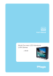
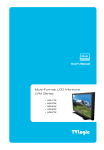
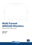
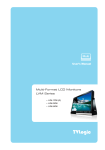
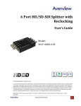
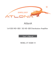
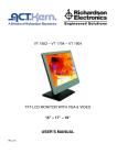
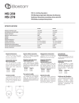
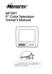
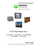
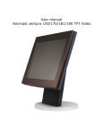
Multi Format
LCD Monitor
User’s Manual
LVM-070W
Contents
Warnings ............................................ 3
Features.............................................. 3
Name & Function of Each Part............. 4
Menu Organization & Adjustment. ...... 7
Menu Contents .................................... 8
Other Functions ................................ 10
Product Specification ........................ 14
Product Lineup.................................. 15
Optional Accessories ......................... 16
2
Compatible with varied SDI signals
Warning
The product is compatible with varied SDI
Signals - 480i, 576i, 720p, 1080i, 1080p,
z Always use set voltage.
1080psF (SDI A, B 2 channel compatible)
- DC 12V 1.5A
Compatible with varied analog signals
z If liquid is spilled on or impacts this product,
The product is compatible with varied analog
please disconnect the product immediately
signals - Composite, S-Video, Component, RGB,
and
etc.
seek
professional
help
before
continued use.
All-in-one system
z Keep unit disconnected during extended
periods of disuse.
Slim and all-in-one type monitor that requires
no
additional
accessories,
which
provides
optimized space utilization.
z Keep unit in a well-ventilated place to
prevent overheating.
Wide Screen compatible
Wide Screen for easier monitoring.
z Do not install the product near any heatgenerating equipment. Also, keep the
product out of direct sunlight or dusty areas.
DC compatible
The product may be powered by normal AC
source, but also 12V DC source.-
z Only
clean
the
product
with
a
noncommercial, mild and neutral detergent.
Remote control function
Remote-controlled simply with cable connection
z When transporting the product, make
use of its original packaging for safer
without
additional
peripheral
equipment
attached to unit.
carriage.
VGA function built-in
No other product can use common VGA
Features
Monitor.
In addition, the product is compatible with
LVM Series units have the following
Wide View Angle, Relocked Active Through
features:
OUT (SDI), VESA Mounting Standard, 300:1
contrast
ratio,
450cd
brightness,
user
interface and rack mountable among others.
3
Name & Function of Each Part
4
<FRONT>
z
ANALOG INPUT
z
CHROMA/PHASE
Used to select desired ANALOG INPUT. A
Used
to
change
the
CHROMINANCE and
Sub Menu for each analog input connected
PHASE values. Pressing the button once will
can be selected.
activate the CHROMA mode, pressing the
button twice activates PHASE mode.
z
SDI INPUT SELECT
Used to select SDI INPUT A or B.
z
UNDER SCAN
Used to transfer from OVER SCAN mode to
(PHASE may be used only with COMPOSITE and
S-VIDEO on ANALOG mode.)
z
MENU
Used when OSD menu is activated.
UNDER SCAN mode. (Compatible up to SD
1:1 SCAN mode.)
z
DOWN/BRIGHT
Used to navigate menu during OSD menu
z
ASPECT
activation. It may also be used to control
Used to change the monitor ratio on SD
the BRIGHT value when the OSD menu is
signal mode to 16:9.
not active.
z
MARKER
z
UP/CONTRAST
Used to show MARKER on the screen. The
Used to navigate the menu during OSD
type of marker at work may be selected on
menu activation. It may also be used to
the main menu.
control the CONTRAST value when the OSD
menu is not active.
z
H/V DELAY
Used to observe horizontal sync and vertical
z
ENTER
sync simultaneously.
Used to confirm a chosen value (or mode)
during OSD menu activation or inactivation.
z
BLUE ONLY / MONO
You may remove R(red) and G(green) from
z
STANDBY
the input signal and play the screen only
Indicates
with B(blue) signal. Button may be pressed
current setting. The lamp is RED when unit
twice to change the screen to MONO mode.
is
(This mode uses only luminance value.)
standby mode and GREEN during system
power
connected
operation.
to
supply
power
supply
and
and
in
In case of sudden loss of power
unit retains last setting.
5
connection
z
TALLY
LED indicating monitors current status.
<REAR>
z
Input VIDEO connection method
Connector
Composite
Component
S-Video
1
CVBS1
Y
G
Y
2
CVBS2
Pb
B
No Con.
3
CVBS3
Pr
R
C
REMOTE (RJ-45)
Connection for remote control of monitor.
z
Information
VGA IN / FACTORY PGM
Input connection for VGA mode and input
connector for FACTORY PGM allowing for
firmware updates.
Warning!!
Before using this unit make certain to
connect the power supply before
z
CVBS1/Y/G/S-Y (BNC)
connecting a signal to any of the inputs.
Signal input terminal used for COMPOSITE1,
The unit may not function properly if a
S-VIDEO Y, COMPONENT Y, RGB G signals.
signal is connected before the power
supply is connected. As an example: the
z
CVSBS2/Pb/B (BNC)
unit will not function properly when using
Signal input terminal used for COMPOSITE2,
an RCA-to-BNC (BNC-to-RCA) connection
RGB B, COMPONENT Pb signals.
if the signal is connected to the input
before the unit is connected to the power
z
CVSBS3/Pr/R/S-C (BNC)
supply.
Signal input terminal used for COMPOSITE3,
S-VIDEO C, COMPONENT Pr, RGB R signals.
Information
The UNDER SCAN and the MARKER button are
z SDI-IN (BNC)
including the ASPECT and H/V DELAY function.
SDI signal input terminals that provide A and
When using, the UNDER SCAN and MARKER
B inputs.
function pay attention become first of all.
z
SDI-OUT (BNC)
SDI signal output terminal used for SDI
output.
z
DC 12V 1.5A IN (XLR, Male)
Used to supply DC power; 12V
6
Menu Organization & Adjustment
The product may be controlled and set
2. Highlight the desired item with the
system-wide through an OSD.
UP/DOWN button.
1) Menu Organization
Below is the organization of the product’s
3. Press ENTER to select an item, make
menu.
sure the item turns red and then change
the set value.
4. Select the desired new value with the
UP/DOWN button.
5. Press ENTER to save the new value
(verified by highlighted field returning to
default black color).
6. Press MENU once again to remove OSD
menu from the screen.
2) Menu Control
You may control various functions using
MENU, UP/DOWN and ENTER buttons on the
bottom-front of the monitor.
3) Menu Control Sequence
Menu control sequence follows the order
below
1. Press MENU button to bring up the OSD
menu.
7
Menu Contents
Below is the description of each function
of the menu.
z CHROMA
This item controls saturation between MAX
(50) and MIN(-50).
z BRIGHT
This item controls the degree of brightness
between MAX(50) and MIN (-50) range.
z
APERTURE
This item controls the picture sharpness.
Sharpness select MIN(-4) and MAX(15).
z CONTRAST
This
item
controls
the
contrast
ratio
between MAX(50) and MIN(-50).
z
MARKER
This selects the marker type when the
MARKER
is
displayed
MARKER
may
only
on
be
the
screen.
activated
by
pressing the MARKER button on the front
z COLOR
of the monitor.
This item controls COLOR TEMP. and is
basically compatible with 5000K, 5600K,
6500K, 9300K and USER modes. On USER
mode, the user may select between R, G and
B values.
Compatible MARKER types are as follows:
MODE
MARKER CLASS
4:3, 4:3 ON AIR
z PHASE
HD
15:9,14:9,13:9
SD 16:9
1.85:1, 2.35:1
This item controls PHASE value (Tone)
between MAX(50) and MIN(-50). However, it
is only available on COMPOSITE and SVIDEO in ANALOG mode.
8
1.85:1&4:3
SD 4:3
16:9
z
CENTER MARKER
This item displays the CENTER MARKER on
the screen. This function operates only
after activating the MARKER function by
z
REMOTE SETUP
pressing the MARKER button on the front
This product is compatible with exterior
of the monitor.
REMOTE CONTROL. The user may access
the remote setup menu from here.
z
AUDIO
This item sets embedded audio channel
z
SAFETY AREA
selects Ch1~Ch16 and OFF.
This item controls the size of the SAFETY
AREA between 80%, 88%, 90% and 93%.
z
SET DEFAULTS
You can use SET DEFAULTS menu to
z
MARKER MAT
This item darkens the area on the outside of
MARKER setting area. The degree of darkness is
between OFF (0) and (7). The higher the number,
the darker MARKER border becomes.
z
MARKER COLOR
This item controls the color when MARKER is
generated. Settable colors are white, gray,
black, red, green and blue.
z
NTSC SETUP
This item sets IRE value in NTSC mode
between 0 IRE and 7.5 IRE.
9
initialize the values of BRIGHT, CONTRAST,
PHASE and CHROMA of the monitor.
Other Functions
(1) Press MENU to call up the OSD menu.
1) ANALOG Mode Usage
This product is capable of processing
all input signals usable in ANALOG
mode. The ANALOG input settings are
as follows:
(1) Press ANALOG button on the front of
the product and activate the menu below.
(2) Select COLOR on MENU and choose USER
(2) Highlight the value you desire by using
among selectable values.
the UP/DOWN button and press the MENU
button to confirm your selection. From this
point the OSD menu operates identically to the
MENU operations discussed above.
Caution!!
(3) Press MENU and store USER mode,
When using ANALOG mode, always check
select one of RED, GREEN and BLUE with
the input method and modify the setting
DOWN button and press ENTER.
as needed for optimized output results.
2) COLOR USER Mode Usage
This
product
provides
USER
mode
where the user can set the color
(4) After the selected value turns red, set
wanted. USER MODE may be used in
the value with the UP/DOWN button, press
the following manner.
MENU again to store the selected value. The
value should be within the range MAX(50)
and MIN(-50).
10
(3) The REMOTE SETUP menu will be
activated.
3) REMOTE Mode Usage
This
product
provides
a
REMOTE
CONTROL mode. The user may connect
the RJ-45 jack to the REMOTE terminal on
the rear of the unit and designate a
function for each pin. The method for
The user may designate functions for PIN1
designating
~ PIN 6. PIN7 is for POWER ON/OFF use
functions
for
pins
is
as
follows:
only.
The
selectable
functions
are
as
follows:
(1) Press MENU to call up the OSD menu.
Menu
Classification
Settable Values
NONE, ANALOG CHANNEL
DIGITAL A,B CHANNEL
TALLY R,G , BLUE ONLY
SD 1:1 SCAN, UNDER SCAN
ASPECT, H/V DELAY
PIN 1~6
16:9,15:9,14:9,13:9 MARKER
4:3, 4:3 ON AIR MARKER
1.85:1, 2.35:1 MARKER
1.85:1&4:3 MARKER
CENTER MARKER
SAFETY AREA 80%, 88%
SAFETY AREA 90%, 93%
(2) Select REMOTE SETUP on MENU.
(4) On the pin to be used, set the function you
desire with the ENTER button and UP/DOWN
button. The method of setting the values is the
same as that for the MENU function discussed
earlier.
11
Pin number designation is depicted below. Pin
(1) Press the ANALOG button to bring up
#8 should be left as the RJ-45 GND.
the OSD menu. Select DVI-ANA and press
the MENU button.
(2) This mode’s OSD MENU is different than
the other OSD MENU.
4) SD 1:1 SCAN Mode
Widescreen models provide not only
an UNDER SCAN mode but also an SD
1:1 SCAN mode. These modes may be
selected as follows:
(1) Transfer to UNDER SCAN by pressing
the UNDER SCAN button on the front of
the monitor.
(2) Press the UNDER SCAN button again
after the mode is shifted to UNDER SCAN
This mode is controlled by DOT PHASE, H
mode to transfer to SD 1:1 SCAN mode.
SHIFT and V SHIFT. The function control
methods are described below.
5) COMPUTER Mode
z DOT PHASE
This product supports VGA mode. If
Use this item for tuning the screen. Controls DOT
user
PHASE value between MAX(31) and MIN(0).
wants
this
model
to
use
Computer monitor, select this mode.
This mode usage is as the following.
z H SHIFT
Use this item to move the entire screen to the left
or right. Controls H SHIFT value between MAX(63)
and MIN(-64).
12
z V SHIFT
Use this item to move the entire screen up or
down . Controls V SHIFT value between MAX(7)
and MIN(-8).
(3) COMPUTER mode is support below
resolution and frequency.
Resolution
Frequency
640 X 480
60Hz, 75Hz, 85Hz
800 X 600
60Hz, 72Hz, 75Hz, 85Hz
1024 X 768
60Hz,70Hz,75Hz,85Hz
1280 X 768
60Hz
1280 X 1024
720 X 400
13
60Hz
(Sub-sampling mode)
70Hz
Product Specification
Below is the product specification
Specification
LVM-070W
LVM-084
LVM-170W
LVM-230W
V GA IN
1 x D-SUB
DV I IN
Input
3 x BNC
2 x BNC
SDI 2 Channel Input
Output
1 x BNC
Selected SDI Channel (Activ e Through Out)
Analog
Composit / S-V ideo / Component / RGB
HD-SDI
1.485Gpbs
Input Signal
Analog
Input
Spec
Analog Input
270Mbps
SD-SDI
V GA
640 X 480 / 800 X 600 / 1024 X 768 / 1280 X 768 / 1280 X 1024* / 720 X 400
Composite
1.0V pp (With Sy nc)
S-V ideo
1.0V pp(Y with Sy nc), 0.286V pp(C)
Component
1.0V pp(Y with Sy nc), 0.7V pp(Pb,Pr)
RGB
1.0V pp(G with Sy nc), 0.7V pp(B,R)
**
1080i (60 / 59.94 / 50)
SMPTE-274M
SDI
Input Signal
Formats
LVM-240W
1080p (30 / 29.97 / 25 / 24 / 24sF / 23.98 / 23.98sF)
SMPTE-296M
720p (60 / 59.94 / 50)
SMPTE-260M
1035i (60 / 59.94)
SMPTE-125M
480i (59.94)
576i (50)
ITU-R BT.656
Size
7.0"
8.4"
17.1"
23.0"
24.0"
Resolution
800 x 480 (15:9)
1024 x 768 (4:3)
1280 x 768 (15:9)
1366 x 768 (16:9)
1920 x 1200 (16:10)
Dot Pitch
0.0635 x 0.1905 mm
0.165 mm
0.29 mm
0.372 mm
0.27 mm
Color
262K,18bit
16.7M(true), 24bit
16.7M(true), 24bit
16.7M(true), 24bit
16.7M(true), 24bit
V iewing
Angle
H: 130 degrees
H: 170 degrees
H: 170 degrees
H: 170 degrees
H: 178 degrees
V: 100 degrees
V: 170 degrees
V: 170 degrees
V: 170 degrees
V: 178 degrees
450cd (center)
400cd (center)
450cd (center)
500cd (center)
500cd (center)
Contrast
300:1 400:1
400:1 800:1 1000:1 Display Area
152 x 91 mm
170 x 128 mm
372 x 223 mm
508 x 285 mm
518 x 324 mm
Power 12V DC
12V DC
AC 100 - 240V
/ 12V DC
AC 100 - 240V
(50/60Hz)
AC 100 - 240V
/ 24V DC
Power Consumtion (Approx.)
16Watts
16Watts
(DC)
16Watts(DC)
16Watts
45Watts(AC)
36Watts(DC)
85Watts
90Watts(AC)
72Watts(DC)
LCD
Luma of
White
Operating Temperature
0°C to 40°C ( 32°F to 104°F )
Storage Temperature
-10°C to +50°C ( 14°F to 122°F )
Main Body (W x H x D)
215×133×50
TBD
215×177×59
210
x 175 x 60
407×309×80.8
405 x 305 x 80
550 x 355 x 97
550×355×96.8
550×388.4×96.8
555 x 390 x 98
Main Body (with stand)
TBD
230 x 190
x 80
415×329.5×120
435 x 320 x 120
558×376×150
578
x 374 x 150
558×413.4×150
588 x 410 x 150
2.1Kg
6.8Kg
10.2Kg
13 Kg
DC Power Adapter
AC Power cord
AC Power cord
AC Power cord
Carrying Case
Carrying Case
Weight
Accessory Option
1. TBD
4Kg
DC Power Adapter
Carrying Case
V-mount
V-mount
V-mount
19"
Rack
Mountable
Kit
19"Rack Mountable Kit
Hood / Handle
(4U)
(Dual
Monitor)
(3U) (Dual Monitor)
19" Rack Mountable Kit
Soft Bag(Hood)
(7U)
*VGA 1280 X 1024 mode is sub-sampling mode.
14
Product Lineup
• LCD RESOLUTION 800 X 480 (16:9)
• COLOR 262K , 18 bit
• CONTRAST 300 : 1
• WEIGHT 1.4 Kg
• LCD RESOLUTION 1024 X 768 (4:3)
• COLOR 16.7M, 24 bit
• CONTRAST 400 : 1
• WEIGHT 2.1 Kg
• LCD RESOLUTION 1280 X 768 (15:9)
• COLOR 16.7M, 24 bit
• CONTRAST 400 : 1
• WEIGHT 8.3 Kg
• LCD RESOLUTION 1366 X 768 (16:9) / 1920 X 1200 (16:10)
• COLOR 16.7M, 24 bit
• CONTRAST 800 : 1 / 1000:1
• WEIGHT 10.2 Kg / 13 Kg
15
Optional Accessories
Rack-Mountable Kit
V-mount
Carrying Case
16
Tripod Head
Hood & Handle