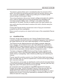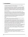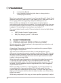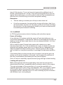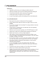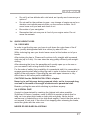
1
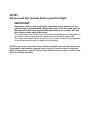
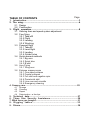
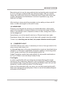
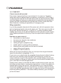
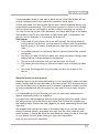
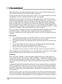
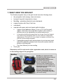
user manual
ek
Dud
ul.
s,
der
i
l
ag
Par
ko,
els
Osi
1
3
0
86U,
a 2
n
l
tra
Cen
52
+48
d,
n
a
Pol
0,
174
324
eu
ek.
dud
@
t
or
exp
www.dudek.eu
NOTE!
Please read this manual before your first flight
IMPORTANT:
Remember to fill in and send us the registration card, sewn on to the
trailing edge of the paraglider. When we receive it, we will send you the
Warranty or AeroCasco confirmation (whichever you choose). You will
also receive some small gifts along.
The confirmation will allow us later to identify the paraglider, to categorise it in
its proper insurance group and to determine the insurance expiry date.
Also, the confirmation will be useful in future, in case of selling the paraglider
(it will allow the new owner to keep all the benefits).
NOTE! If you are not the first owner of the paraglider, you should send us the
registration confirmation together with a copy of previous users' logbooks
(total of flying hours) within 14 days from the date of purchase, in order to be
able to keep the warranty.
TABLE OF CONTENTS
Page
1. Introduction......................................................................................3
2. The wing..............................................................................................4
2.1 Design
2.2 Construction
3. Flight operation............................................................................8
3.1 Steering lines and speed system adjustment
3.2 Free flying
3.2.1 Take-offt
3.2.2 Flight
3.2.3 Landing
3.2.4 Winching
3.3 Powered flight
3.3.1 Take-off
3.3.2 Level flight
3.3.3 Landing
3.3.4 Golden rules
3.4 Quick descent methods
3.4.1 Big ears
3.4.2 Spiral dive
3.4.3 B-stall
3.5 Acro Flying
3.5.1 Wing over
3.6 Extreme manoeuvrese
3.6.1 One sided collapse
3.6.2 Frontal collapse
3.6.3 Full stall and negative spin
3.6.4 Parachutal stall
3.6.5 Line over and cravatte
3.6.6 Emergency steering
4. Canopy care........................................................................................25
4.1
4.2
4.3
4.4
Storage
Cleaning
Repair
Deterioration - a few tips
5. Technical data.................................................................................27
6. Three Star Security Assistance..........................................28
7. What have you bought.......................................................................31
8. Rigging tables.........................................................33
9. Risers........................................................................................38
Leading
edge
Cell
Trailing edge
Cell
openings
Main suspension
lines
Stabilizer
Risers
TST line
Fot. John Coutts
USER MANUAL
1. INTRODUCTION
CONGRATULATIONS!
We are pleased to welcome you among the growing number of Dudek
Paragliders pilots. You've become a proud owner of state-of-the-art
Plasma paraglider. Extensive development, application of the most
modern methods and thorough testing make the Plasma a user-friendly
paraglider, offering the pilot a lot of fun combined with great
performance.
We wish you many enjoyable and safe flying hours.
DISCLAIMER
Please read this Manual carefully and note the following details:
$
$
$
$
$
The purpose of this Manual is to offer guidelines to the pilot using the
Dudek Plasma wing and it is by no means intended to be used as a
training manual for this or any other paraglider in general.
You may only fly a paraglider when qualified to do so or when
undergoing training at an accredited School or with an Instructor.
Pilots are personally responsible for their own safety and their
paraglider's airworthiness.
The use of this paraglider is solely at the user's own risk! The
manufacturer and distributor do not accept any liability connected with
this activity.
This paraglider on delivery meets all the requirements of the EN 926-1
and 926-2 regulations. Any alterations to the paraglider will render its
certification invalid.
NOTICE
Dudek Paragliders warns that due to the constant process of development
the actual paraglider may differ slightly from the one described in the
manual.
3
2. THE WING
WHO SHOULD FLY Plasma?
You are a good pilot and you like to compete. You are looking for a top
performing wing, while preserving considerable stability and passive safety. You
are fond of reflex-aerofoil characteristics, especially its speed and tuck-resistance
- so in short, Plasma is a paraglider for you!
2.1
DESIGN
Plasma is a reflex-aerofoil paraglider for experienced pilots looking for
maximum performance available. Nevertheless we worked hard in order to
obtain passive safety level comparable to that of our other reflex wings, so
that Plasma doesn't differ from Plasma in behaviour. Despite its higher
aspect ratio and shorter brake travel pilots of advanced free-flying wings
won't be much troubled either, only people so far flying classic (i.e. nonreflex) PPG wings will have to get used to it.
While designing it we put a lot of effort into flight safety, pleasant handling,
good performance and wide speed range, so that it will satisfy a great many
pilots. In many prototypes leading to final Plasma version we have tested
several airfoils based on our own Dudek Reflex Airfoil. Often we tried to
decrease its stability in order to achieve take-off and handling, but invariably
we ended with worsened safety at full speed with little improvement
elsewhere.
We feel safe to declare the Plasma to be the best wing available in its class.
The fundamental feature of a good PPG wing is its great stability and tuckresistance. A good PPG wing must be a very stable and tuck-resistant craft.
When this is achieved, the user does not have to concentrate all the time on
piloting, thus saving energy for navigation, taking pictures or simply enjoying
the flight. In addition the faster and safer your paraglider is, the more often
you can fly.
While the Plasma was designed to retain all the features of a conventional
paralider, the application of a reflex aerofoil section added several new
qualities. First of all, using that profile means that the wing stability does not
depend exclusively on the pilot's weight and actions. It maintains its own
pitch attitude, rising and falling through thermals while remaining stable
above your head, without need for so much pilot input.
Generally speaking the reflex profile is a special kind of aerofoil section. The
specific static pressure distribution creates a situation where at low attack
angles, only the wing fore part (some 60% of the chord) is producing lift,
while the rear 40% of the chord creates an effective stabiliser against
excessive decrease of the attack angle.
4
USER MANUAL
The trimmer system allows you to considerably raise the rear part of the
airfoil, thus effectively reducing projected chord and surface area by some
30%, giving the paraglider a higher wing loading and increased speed
without change in the angle of attack.
The centre of pressure also moves forward, adding enhanced pitch stability.
Such a shift of loading gives the wing exceptional tuck-resistance and
increases projected aspect ratio, resulting in much better flight data,
especially at full speed. Should you require more lift at lower speeds, the
rear section can be pulled down to restore a full airfoil, effective along the
whole chord.
Piloting the Plasma actually reminds one more of flying a conventional
powered aircraft than a paraglider.
Below we will try to give you a closer look at some of the remarkable Plasma
features.
2.2
CONSTRUCTION
Plasma's canopy was designed in our Canopy Shape Guard system,
comprising many elements resulting in exceptional coherence and stability of
the shape. Below you will find a short description of CSG subsystems.
The Plasma has an elliptical planform with slightly rearward swept tips.
Every second cell is divided in three, with ribs additionally supported by
diagonal VSS (V-shaped supports) system. Such arrangement ensures a
smooth top surface, exact aerofoil reproduction across the entire wingspan
and yet more importantly, minimal number of suspension points.
The lower surface has a RSS (Reinforcing Strap System) applied in the
wing’s interior. RSS is an ballooning-independent reinforcements system
made entirely of paragliding fabric, effectively stiffening and stabilizing the
canopy.
Plasma’ aerofoil is another product of our Dudek Reflex Airfoil technology. It
was calculated with our previous experiences in mind and thoroughly tested
with numerical methods
The suspension points areas are additionally reinforced with laminated fabric
so that loads are equally distributed on three planes: vertically (with the ribs),
diagonally (with VSS system) and level through RSS.
All crossports have been prepared using OCD (Optimised Crossports
Design) technology. Carefully designed shapes of the openings and their
optimal placement between stress lines guarantee efficient pressure
distribution in the canopy and its quick inflation. These openings are scaled
together with the ribs, so that their replicability is flawless and they do not
disturb the aerofoil in any way.
5
The Plasma’ leading edge is closed to airflow, and its precise shape is
supported by reinforcements of laminated fabric.
Cell openings are positioned on the undersurface in the vicinity of leading
edge. Their position was chosen very carefully, so that they got maximum
ram effect in possibly many flight situations. In several places the leading
edge features our CCS (Closed Cell Structure) system – this is a number of
closed cells in most important locations. It’s goal is to hinder the backflow
form the cells out and thus to facilitate their refilling and canopy recovery in
case of a collapse.
Each wingtip consists of four additional cells creating stabilizers. They
maintain correct tension of the canopy, improve directional stability and play
important role in keeping your turns efficient and even. In the very tips there
are cleaning slots, placed there for easy removal of dirt form inside the wing.
Careful selection of modern fabrics and design solutions brings about great
strength and durability of the Plasma. All materials used come from marked
production batches, and each production step can be verified down to
identification of specific worker and controller.
Fabric
Each kind fabric has it unique features and characteristics. We composed
them so that their interplay creates a perfect blend.
The Plasma’ upper surface is made of Porcher Skytex 45 Evolution fabric
(formerly named Aquatic), perfectly proven in our earlier wings. Basically it's
a nylon material covered with superb E85A impregnate, introduced into
mass production in January 2002 after a series of extensive laboratory and
real flying tests. Such covered fabric is not very stiff and - what's most
important - has increased tear, stretch and UV resistance. It is not siliconed,
so minor repairs can be easily made with self-adhesive strips.
The lower surface is made of Skytex 40 Classic with E38A impregnate. This
fabric has a great weight/resistance ratio and is one of the greatest Porcher
successes in providing proper materials for the paragliding industry.
The ribs must be as rigid and stretch-resistant as possible. We found these
qualities in Skytex 40 Hard with E29A impregnate. All reinforcements are
made of SR-Scrim.
Rigging system
Most of Plasma's rigging is sheathed by a coloured polyester layer which is
covering brownish Technora core. Low number of lines required such
composition, featuring high strength and stretch-resistance.
The rigging system consists of individual lines with stitched or plaited loops
at each end.
6
USER MANUAL
The upper level (gallery) lines start at the attachment points. Lines of this
layer are gathered by middle layer lines. These in turn connect by twos or
threes to the main suspension lines, which are attached to the risers with
triangular quick links (maillons). To prevent their slipping off, the lines are
kept together with a rubber 'O ring'. All the maillons are made of corrosion
resistant, polished stainless steel, ensuring excellent strength and durability.
Brake lines run from the trailing edge through consecutive cascades to the
main steering lines, which are lead through pulleys connected to the rear
risers and then fixed to the brake handles.
Steering lines do not carry any load until the brakes are applied. Some of the
upper layer steering lines are additionally led through rings sewn into the
trailing edge. Because of this feature the trailing edge is shortened on
application of the brake, so that steering becomes lighter and more effective.
All the lines are distinguished with colours depending on their strength and
diameter as follows:
2,3 mm; strength: 420 daN; colour: celadon (willow green),
1,8 mm; strength: 280 daN; colour: red and orange (the latter for
pulling big ears),
1,5 mm; strength: 190 daN; colour: violet,
1,3 mm; strength: 140 daN; colour: green,
1,2 mm; strength: 90 daN; colour: blue.
(given colours are subject to slight changes).
In order to reduce overall drag there are unsheathed lines in the upper layer,
with 45 or 80 daN strength.
The risers
For the Plasma we have chosen four-way risers equipped with:
$
ELR (Easy Launch Riser) system. This is an specially marked A
rises (gold ribbon)
$
speed-system affecting A, B and C risers when engaged;,
$
trimmers of red band with visible scale (red – slow and blue – fast
trim setting), designed for quick and easy replacement in case of
deterioration;
$
two levels of the pulleys, to be used depending on the hangpoint
$
Tip Steering Toggle system (see details on pages 10).
For quick and easy recognition in emergency, some of the risers are
distinguished with coloured band as follows:
A
- gold (used for launching)
A'
- blue (used for big ears)
7
B
D
- red (used for B-stall)
- grey (needed to keep the glider down in strong winds or
interrupting the launch).
Main A row suspension lines connect to an A riser (gold) and A' (blue). B and
stabiliser lines go to B riser (red), C lines (black) go to C riser, and D lines to
D riser (grey), which through pulleys keep the steering lines too.
Brake handles are attached to the steering lines at optimal places,
guaranteeing safe and effective operation. On the main brake lines there are
two points marked, higher and lower, to be used depending on the harness
hangpoint. On adjusting the steering lines see chapter 3.1.
Our newest brake handle used in Plasma besides its robust yet light design
features:
$
DCT (Double Comfort Toggle) system,
$
EK (Easy Keeper) system - look below
3.
FLIGHT OPERATION
3.1
STEERING LINES AND SPEED SYSTEM ADJUSTMENT
We strongly advise following actions to be supported by an instructor or at
least an experienced pilot.
A brand-new Plasma has its steering lines positioned for powered flight in
high hangpoint configuration.
The risers of the Plasma are shorter than in most paragliders, so the
differences in hangpoints present somewhat smaller problem. Still, there are
two sets of pulleys prepared, higher and lower (see risers scheme on page
37). Also on the main steering lines there are two spots marked for brake
handles to be accordingly fixed.
When flying with lower hangpoints (or free-flying) the brake lines are to be
run through the higher pulleys only, and the brake handles should be
positioned at higher marks, thus shortening the brakes in general. The rule
is simple - higher hangpoints require longer brake lines, lower hangpoints
require shorter lines.
Before you take your Plasma on powered flight, we strongly advise to try
out everything first. Hang up the entire PPG unit with ropes, sit in the
harness and have someone pull up the risers. You must make sure that in
flight you will always be able to reach the brake handles, even if the airflow
blows them away.
While being suspended in this way, you have a perfect opportunity to adjust
8
USER MANUAL
the speed system too. The speedbar should not be pulling pull its lines (and
risers) when it is not applied. Neither should it be too loose, for it could catch
the propeller then.
An additional way to check the whole configuration out is to visit take-off site
in steady winds. With the engine off, fill the wing and take it up over your
head. When it stabilises, check that the brakes are loose and are not pulling
the trailing edge. There should be a spare inch or so before they activate.
Remember that it is always safer to set the margin of play too big than too
small. And, most important, the setting must always be symmetrical.
3.2 FREE FLIGHT (no power unit)
Although the Plasma according to its design book is a fast PPG wing, it
behaves surprisingly well as a classic paraglider too and can be used as
such without any changes.
The essential difference between Plasma and classic paragliders means is
due to its increased tuck-resistance (both during start and flight) and greater
speed range it can be safely flown in strong conditions. Generally (and
paradoxically from traditional point of view) the faster you fly, the safer is
your flight.
3.2.1 TAKE-OFF
In case of classic launch we recommend that after laying out the wing all
lines be taut, without unnecessary play. The Plasma is pulled up with A risers
only. The optimal trim setting is “0” (when launching for powered flight) or
fully closed (when launching free-flight). Applying steady pressure on the A
risers move forward. The wing practically does not overshoot, so the front
collapses that otherwise happen quite often at launch, with the Plasma
occur rarely. Instead it kind of waits for you to catch up with it.
In case of reverse launch we also recommend abovementioned trim
settings. Due to lack of overshooting take-off is easy, pilot has only to brake
slightly. Reverse launches can be executed without any problems even in
weak wind (1,5 m/s).
Caution!
During take-off it is important to keep the risers under pressure until
almost airborne. Reflex profile used has an inherent tendency to
increase the angle of attack. In effect, Plasma can lag behind the pilot
when not pulled up appropriately.
9
Tip Steering Toggles (TST)
handle
TST
TDS
In order to facilitate steering the wing while at maximum speed configuration
(opened trimmers and full speed-bar) we've invented our own novel system of
controlling the stabilizers. Prior to grabbing miniature TST-handles (Tip
Steering Toggles) pilot places the main steering handles in a special Toggle
Docking Stations, equipped with strong neodymium magnets. In this way you
can comfortably steer the wing via TST handles, not worrying about the brakes
getting tangled.
Easy Catch bar
The Easy Catch Bar is a medicine for all those having troubles with finding
bar inflight. It is designed so that the bar always remains forward of the lines.
The bar itself is very durable – it is going to serve you long.
10
USER MANUAL
Double Comfort Toggle (DCT)
DCT: in order to satisfy different needs of our clients we have created a Double
Comfort Toggle system. With this solution it is possible to have your brake
handles in stiff or soft configuration, with no need to buy another set of toggles
and replace them every time. All you have to do now is take out the stiffening rod
and there you are - the soft handle is ready to use.
Easy Keeper (EK)
Easy Keeper is the name of our new indigenous way to hold the brake handles at
the risers.
The strong neodymium magnets keep them firmly in place, while both attaching
and releasing goes smoothly and easily. This idea was developed especially for
the PPG dedicated paragliders, for there is often a need to take your hands off the
brakes to check or fix things. With Easy keeper you can easily secure the brakes
in flight, thus minimizing danger of their contact with the propeller.
11
3.2.2 FLIGHT
The increased speed range of Plasma may demand some attention.
Nevertheless, once you have mastered these additional aspects, flying will
become pure pleasure. Good handling will let you make the best use of
thermals, and increased speed on glides means that your presence in
sinking air will be shorter.
To avoid stalls when braking with slow trims setting (red area), their
movement is restricted by the tape sewing. (Note: it is possible to push the
sewn tape through the buckle with both hands to replace it, but normal
operation range is restricted by said place.
When the trims are fully opened (blue area) the wing becomes faster and
stiffer, increasing its stability even more. The brake forces increase too, as
well as the distance to the stall point. The radius and
bank angle in turns grow proportionately to the growing brake forces. If the
trims are set fast (or fully opened) and the wing is not flown near the ground,
a switch to TST steering is advised (see page 10). TST system can be used
in all speed system & trim configuration.
Speed system use
Full application of the speed system increases flight speed by some 30%. In
contrast to most paragliders it does not decrease wing stability, in fact
Plasma seems to counter the turbulence even better then. Still, if you
encounter serious trouble, it is advisable to release speedbar. With
application of the speed system the brake forces increase considerably, and
brake effectiveness decreases. At maximum speed and fully opened trims
we strongly recommend steering the wing with TST system. Turns executed
in this way will be slightly wider, but strength needed to initiate turn will be
smaller and there will be no decrease in speed.
It is strongly recommended that speed system is used with half- or fully
opened trims. Engaging speed system with closed trims (red area) can lead
to a front stall.
3.2.3 LANDING
With closed trimmers (red area) Plasma lands like any other paraglider. The
brake forces, initially low, are growing proportionally, giving ample warning
before stalling. Still you should be careful when flying at low speeds until
fully familiar with brake operation.
When landing with trims set fast (blue area) may require proportionately
more space, as the paraglider has a lot of kinetic energy and careless
application of brakes may even cause the wing to climb.
12
USER MANUAL
Most pilots get to know the wing relatively fast and quickly gain enough trust
to fly it in stronger conditions than they did ever before. Still, you should
always be careful when flying low. Remember that Plasma flies faster than
ordinary paragliders and sometimes it can be of importance (e.g. when
landing on a slope).
After landing in strong wind the paraglider can be safely put down with B
risers, or with a strong pull on the rear D risers.
3.2.4 WINCHING
Plasma is not designed for winching. As mentioned before, reflex profile
used in the wing has an inherent tendency to increase the angle of attack.
While in normal flight such a disposition makes it safer, during winch start it
can be dangerous.
Nevertheless, a lot of successful winches on Plasma have been made.
Experience shows that it should only be done with opened trims (blue area).
To sum it up: winching can be done, but proper attention must be paid.
3.3
POWERED FLIGHT
CAUTION: Before each start it is necessary to have a thorough check of the
wing, harness and power unit.
In powered flight most of the wing characteristics remain as described above
(chapter 3.2). Still there is additional information needed, concerning power
output, proper matching of the wing/engine/propeller etc.
Dudek Paragliders cannot take responsibility for all possible combinations,
but if you contact us we are always ready to help.
First flights
In order to get familiar with your wing we recommend flying with closed
trimmers at first (read area), because in this configuration Plasma behaves
asa standard wing. Flying like that try pulling the brakes some until you feel
resistance, usually it will be at about 1/4 of the range.
Once you feel competent with your wing, you can start experimenting with
faster trim settings and speed system. Learn to use all the additional speed
and safety of the Plasma.
13
3.3.1 TAKE OFF
Classic launch with no wind
Even when it seems that there is no wind at all, it is rarely so. Therefore
always be careful in determining the conditions, as because in PPG flying it
is most important that the launch and initial climb are performed with a head
wind (the danger of losing your airspeed while crossing the wind gradient is
greatly reduced). Special attention must be paid to trees, power lines and
other obstacles, including the possibility of emerging rotors.
Wing preparation
Lay out the paraglider downwind of the power unit, with all suspension lines
taut and pointing toward center of the power unit. The risers are to be laid on
the ground. Set the trimmers at “0” (see fig. 2). In strong conditions faster
settings (blue area) can be advised. Make sure that you warm up the engine
while standing windward of the wing. Stop the engine before clipping in the
risers.
Now have a quick check if:
$
the helmet is on and locked,
$
the risers are clipped in the carabiners,
$
the trimmers are set,
$
nothing will get in propeller's way,
$
speed system is running without problems,
$
steering lines and handles are free and not twisted,
$
engine delivering full power,
$
airspace is clear for take off.
When you are sure everything is OK, you can clip in the wing and execute
launch as described in paragraph 3.2.1.a.
From now on you should steer the paraglider facing forward, without looking
back over your shoulder (when the wing is low behind you, turning can
cause some lines to get in the propeller). Also, possibly falling on your back
and the propeller is dangerous (and costly!) so this should be avoided at any
price, even that of some damaged lines!
During launch, when you feel that the strain on both risers is equal, open up
full power and lean back to counter the engine thrust, so that it can push you
forward rather than to the ground. The best option is not to use the brakes,
allowing the paraglider to rise as it was laid out. If it starts to swerve from its
course, just pull the opposite riser and run under the centre of the wing while
preserving starting direction. If the wind suddenly weakens, give a stronger
pull on the risers.
14
USER MANUAL
If the paraglider drops to one side or back too far to be lifted again, kill the
engine, interrupt launch and check the conditions once again.
As the wing rises, the forces grow lighter and it should stabilise above your
head without overshooting. This is the best moment to check if it is inflated
well and the lines are not tangled, but do it without stopping nor turning. If
you feel the forces on the risers decrease, run faster and let go of the risers.
See whether there is any opposition on the brakes and, if necessary, use
them to correct direction or to increase lift at take-off.
Remember:
$ If the cage of your power unit is not stiff enough, the risers strained
during launch can deform it to the extent of collision with the propeller.
Before giving it full power, check that the cage does not catch any
lines.
$ Any brake operation (or steering inputs in general) should be smooth
and gentle
$ Do not try to take off until you have your wing overhead. Hitting power
before that can cause dangerous oscillations
$ Do not sit in the harness until you are sure you are flying!
$ The faster the trim setting is, the more brake input is required to take
off
$ The lower the hangpoints of your power unit are, the easier is the
launch.
Reverse launch in strong wind
Reverse launch can be executed holding in one hand both A risers and one
brake, throttle and the second brake in the other hand. With a decent wind it
is by far the best way. In weaker wind it is better to prepare a classic launch,
as running backwards with an engine on your back is not an easy thing to
do.
It is reasonable not to pull the wing up until you are really determined to
launch, especially when it is clipped in.
Lay down the rolled paraglider with the trailing edge facing the wind. Unfold
the wing enough to find the risers and check that no lines are looped over
the leading edge. Stretch the risers against the wind, separating the left and
right one.
We suggest that you lay the risers in the same way as you will be turning
during a reverse launch, and place one riser over the other, with the rear
risers upmost. It should be done this way because once you clip in, the cage
of your power unit will make turning on your own impossible.
Now run the pre-launch checklist.
15
After warming up the engine put the power unit on, turn to face the wing, go to
the risers and clip them in the appropriate carabiners.
Pulling on the front and rear risers open the cells. It is a good idea to pull up the
wing briefly in order to check that the lines are not tangled.
Holding the risers, brakes and throttle as described above, pull the front risers
and raise the paraglider over your head. On most occasions you will not have to
brake it, especially if the trimmers are set for fast flight (blue area). Perhaps it
does not agree with our experience, but this is the way the reflex profile works.
When the trimmers are opened (set above “0”), the Plasma profile stabilises the
wing and does not allow it to surge forward. It can even stay back a little - in such
case pull the brakes a little and the glider will come forward.
Once you have it overhead, turn around, open the throttle and take off. As with
the classic launch, in this case too you have to find such combination of
trimmers, brakes and throttle settings that will give you the best speed and rate
of climb.
Remember:
$ You are launching with your hands crossed. You have to really master this
technique before trying it with a running engine on your back
$ Any brake operation (or steering inputs in general) should be smooth and
gentle
$ Do not try to take off until you have your wing overhead. Hitting the gas
pedal before that can cause dangerous oscillations
$ Do not sit in the harness until you are sure you are flying!
$ The faster the trim setting is, the more brake input is required to take off
When clipping in the crossed risers, you can find proper connection of the speed
system particularly hard. Be careful not to confuse the risers!
Climbing
Once you took off safely, continue heading against the wind, using brakes to
correct rate of climb. Do not try to climb too steeply - attempts to increase climb
rate by pulling the brakes will have an adverse effect - due to the additional drag
actual rate of climb will worsen, and with the throttle fully open even a stall can
happen.
In powered flight the Plasma behaves more like an aeroplane than a paraglider,
and it is good idea to think about it in this way. If there are no obstacles present,
it is by far safer (and more impressive for the spectators) to fly level for a while
after take-off and gain some speed before converting it to height with a brief pull
on the brakes.
Another reason not to try climbing too steeply is the risk connected with engine
failure at low altitude. Although the Plasma in a steep climb does not stay back
so much as conventional paragliders do, the low speed is more likely to cause a
16
USER MANUAL
stall. Besides, you should always be able to land safely in case of engine
malfunction, so it’s better not to take unnecessary chances, and better to fly
with a safe margin of speed.
Depending on the power unit geometry, it is possible that after take-off you
will notice a propeller torque (turning moment). It will try to turn you around,
so be prepared for counter-steering with a brake or harness cross-bracing. If
it happens during steep climb on slow trim and full power, beware of the stall
possibility.
Due to typical PPG feature - considerable vertical distance between thrust
axis and wing chord - the range of safe power operation is closely connected
to your skills and equipment.
Power-unit induced oscillations
Certain configurations of engine weight, output and propeller diameter can
cause serious oscillations, during which the pilot is lifted to one side by the
torque effect, swings down due to his weight, then is lifted again and so on.
To avoid this you can:
$
change the throttle setting and/or
$
adjust the cross bracing to counteract the torque, if there is one
$
present and/or
$
shift yourself to the other side of the harness and/or
$
change the trimmer setting.
The best method is to fasten opposite cross-bracing, or apply some weightshift. Such oscillations usually occur at full power - the greater the engine
output and propeller diameter, the bigger the swings. In addition there are
often too late or wrong pilot reactions, increasing the trouble instead of
solving it. In any case the safest way to deal with this question is to close the
throttle and release the brakes. Especially less-experienced pilots tend to
overreact. It is called a pilot-induced oscillation, and proven solution is to
leave the brakes alone.
3.3.2 LEVEL FLIGHT
Once you have gained safe height after take-off and wish to go for a route,
you can turn onto the right direction, fully open the trimmers and let off the
brakes. If the conditions are turbulent it can look foolhardy, but it is the
feature of the reflex profile - the faster you fly, the more stable is your
Plasma. That's why you really can confidently release the brakes and enjoy
your flight.
17
CAUTION: Some pilots with previous free-flying experience may have a
well-grounded habit of keeping the brakes slightly applied at all times.
Such a technique, while quite reasonable on a free-flying wings as it
allows for quick pilot reactions and decreases sink, is not advisable on
reflex-profile wings. When you pull the brakes, the Plasma profile loses
its self-stabilizing features.
If you happen to have a variometer or altimeter aboard – watch it. In level
flight it is very easy to start climbing unintentionally. The instruments will help
you optimise speed and fuel economy. Of course each flight will depend on
current configuration of your gear, but thanks to its ability to fly safely without
constant piloting the Plasma will let you adjust everything to the best effect.
Good knowledge of weather conditions (e.g. wind at different altitudes) and
intelligent use of thermals, convergence and other kinds of lift will help you
greatly reduce fuel consumption and increase flight range.
Of course the engine is always there to bring you in the right place. Do not
hesitate to lead the Plasma into tight thermalling then, and you will be
surprised how efficient it is. Possible shortening of the trimmers will make the
climb ratio even better.
Trimmers and speed-system operation
The reflex wing section enables the Plasma pilot to use a wide range of
trimmers and speed-system action. You are free to experiment with all
possible settings, as long as you are on safe altitude.
Fully opened trimmers (blue area) increase the speed and stability of the
wing, and with it also its ability to cope with turbulences and overall
penetration. As forces on the brakes grow at high speeds, the weightshifting
or steering with TST system becomes increasingly effective. Turns executed
in this way are slightly wider, but needed steering force will be smaller and
airspeed will not decrease.
With slow trimmer settings (red area) there is an improvement in sink and
steering forces diminish, so exploring the thermals becomes possible.
Worth noting is Plasma's impressive speed range - the maximum speed is
over three times greater than its stall speed.
Study drawings of trimmers and speed-system setting, as well as their
influence on the wing shape.
Independent of the current wing configuration and speed, turns can be much
tightened and more effective with differential brake operation. Slight use of
the outer brake (with considerable amount of the inner one) will diminish the
18
USER MANUAL
loss of lift during turn. Turns can be much improved by additional use of
throttle, speed-system etc. as well. Once with growing experience you will
master these techniques, you will be able to execute fully coordinated and
effective turns, that will bring to mind the aeroplane handling.
Remember:
$
Trimmer setting is another part of the pre-start check list!
$
If it will be asymmetric, the wing will be turning all the time. And if you
will inadvertently set them off, the reflex profile of the Plasma will keep
the wing level, so after opening the throttle you'll start to descend with
increased speed instead of climbing.
3.3.3 LANDING
In PPG flying there are two kinds of landing: with and without power.
Power off landing
At an altitude of 50 metres switch the engine off and start gliding as on a
conventional paraglider. It reduces the chances of damaging the propeller on
landing, but on the other hand there is only one attempt possible - so it has
to be done right!
With or without power Plasma better copes with turbulence on open
trimmers (blue area). So, if the conditions are rough, it is better to make an
approach with greater speed, plan a lot of space (as for a hangglider) and
wear that speed off before touching down. Plasma preserves the energy
well, so there is a long float necessary to exchange the abundant speed for
lift.
If the landing field is not big enough and you have to land on the spot, we
advise you to set the trimmers in red area. It will increase lift coefficient of
the wing, simultaneously decreasing its sink rate and speed.
Such an action is especially important when flying with high surface loading.
Landing with power on
Make a flat approach with the engine idling, then level out and lose the
speed before final flare. Immediately after touchdown switch off the engine.
The main advantage of this procedure is of course the possibility of a
repeated approach in case of any misjudgement. Still, if you forget to switch
off the ignition before the wing falls down, there is a considerable risk of
damaging propeller, catching lines in it or even suffering injuries connected
with falling on your running engine.
19
Remember:
$
If possible, get to know your landing area before take-off.
$
Whenever possible, get to know the landing field before taking off.
$
Check the wind direction before planning the approach.
$
Landing with power off requires much less space.
$
In case of any doubt, practice the landing until you feel totally safe.
3.3.4 GOLDEN RULES!
20
$
Never place the power unit downwind of the paraglider.
$
Check, double check and then check once again if there is no fuel
leakage.
$
Do you have enough fuel for the flight? It is always better to have too
much than too little!
$
Check if there is nothing loose in the harness, that could possibly
contact the propeller in flight
$
Whenever you encounter a problem, fix it AT ONCE however small!
$
Always put on and lock the helmet before getting in the harness
$
Before each launch run a full pre-flight inspection
$
After landing, control the wing facing the direction of flight, as on
turning you always risk getting lines in the propeller. Turn only if there
is danger of falling on your back
$
Do not ask for trouble - do not fly over water, between trees or power
lines and other places where engine failure will leave you helpless
$
Remember turbulence caused by other gliders or even yourself,
especially when flying low
$
It is not reasonable to let go of the brakes below 100 meters,
because a possible power unit malfunction may require immediate
attention
$
In general never trust your engine, as it can stop at any moment.
$
Always fly as if that’s exactly what it's going to do
$
Unless it is not absolutely necessary (e.g. collision avoidance), do not
USER MANUAL execute tight turns against the torque direction.
Especially when climbing you can easily enter a stall and consequent
negative spin
USER MANUAL
3.4
$
Do not fly at low altitude with a tail wind, as it pretty much narrows your
options !
$
Do not wait for the problem to grow - any change of engine sound or a
vibration can indicate some trouble, or even serious trouble. You'll
never know until you land and check it out
$
Be certain of your navigation
$
Remember that not everyone is fond of your engine noise. Do not
scare the animals.
QUICK HEIGHT LOSS
3.4.1 BIG EARS
In order to get the big ears you have to pull down the outer lines of the A'
risers (usually distinguished with blue colour) by about 50 cm.
While inducing big ears you should never never let the brakes out of your
hands.
After tucking the tips in, Plasma will continue to fly straight with increased
sink rate (up to 5 m/s). You can steer the wing pretty efficiently with weightshifting.
After releasing the lines, the paraglider will usually open up on its own or
you can assist it with a long stroke of the brakes.
For the sake of safety (the possibility of a parachutal stall) it is reasonable to
engage speed system after pulling big ears in order to lessen the angle of
attack of the wing centre. Executing big ears with open trimmers is very
difficult due to the reflex profile stabilisation.
CAUTION! See the PARACHUTAL STALL chapter.
Never try to pull big ears during powered climb, as the increased drag
can lead to increase of the angle of attack and a parachutal stall.
Besides, pulling the ears while climbing is pointless anyway.
3.4.2 SPIRAL DIVE
A spiral is characterised by reaching the highest sink rates possible.
Significant G-forces, however, make it difficult to sustain a spiral dive for
long, as it can place high loads on both pilot and glider. Never do this
manoeuvre in turbulence or at too high bank angles. Control the dive and do
not exceed 16 m/s sink. If the dive is not stopping after releasing the brake,
assist the glider with the outer one.
NEVER DO BIG EARS IN A SPIRAL!
21
In this manoeuvre smaller number of lines is carrying an excessive
load mulitplied by the centrifugal force, what can lead to damage of the
lines or even the paraglider itself (load of a single line can be much
higher than passed in certification trials (i.e. 8 G).
3.4.3 B-STALL
To enter a B-stall, simultaneously pull down both B-risers (red tape) by 10 –
15 cm. The wing will collapse across the entire span along its B-row, the
airflow over top surface will break and canopy surface will be decreased.
Forward movement will be almost completely stopped.
Further pulling B-risers is not advised, as it increases wing instability. If the
canopy forms a horseshoe with both wingtips in front of the pilot, gently
apply both brakes to recover.
To exit a B-stall, the risers should be released in a smooth and decisive
manner.
On quick and symmetrical releasing B-lines the airflow will reinstate and the
wing will surge forward, returning to normal flight. In contrast to standard
paragliders, in case of Plasma there is no need to counter this surge with
brakes - yet another feature of the reflex profile!
CAUTION: see Parachutal Stall.
All rapid descent techniques should be practised in smooth air and
only with sufficient height! Full stalls and spins are to be avoided as
recovery procedures, since irrespective of paraglider type they may
have dangerous consequences!
BY FAR THE BEST TECHNIQUE IS SAFE AND CORRECT FLYING, SO
THAT YOU WILL NEVER NEED TO DESCEND RAPIDLY!
3.5
ACRO FLYING
Plasma is not designed to do any aerobatics.
3.5.1 WING OVER
You make a wingover by performing a series of consecutive, alternating
turns with growing bank angle. Too much banking connected with some
flaws in co-ordination and execution can evoke pretty dynamic collapse.
CAUTION:Steep turn with bank angle over 60 degrees is a prohibited
aerobatic manoeuvre!
22
USER MANUAL
3.6
EXTREME FLYING MANOEUVRES
CAUTION: EXTREME FLYING MANOEUVRES SHOULD ONLY BE
CARRIED OUT DURING SAFETY TRAINING COURSE (INSTABILITY
TRAINING) UNDER PROPER GUIDANCE!
WHILE PROVOKING OR EXITING REAL SITUATIONS THERE IS A
DANGER THAT YOUR ACTIONS WILL PROVE TOO QUICK OR TOO
STRONG, SO YOU SHOULD ALWAYS EMPLOY GOOD JUDGMENT, STAY
CALM AND TAKE MEASURED ACTIONS.
Since all actions required to exit or prevent dangerous situations on
Plasma are typical and pilots flying this wing should already have
proper experience, we are going to describe only the characteristic
features of Plasma.
Description of standard methods dealing with extreme situations can
be found in textbooks.
3.6.1 ONE SIDED COLLAPSE
Even when the trimmers are fully opened or the speed system is engaged,
collapses practically do not occur and can be induced only by a very strong
turbulence.
Still, if it happens, a corresponding counter-steering is required to keep the
Plasma on course. In normal conditions with collapses up to 50% of the
wingspan, Plasma will reinflate instantly and spontaneously.
3.6.2 FRONTAL COLLAPSE
The reflex profile of the Plasma makes it practically impossible, especially at
higher speeds.
During tests we succeeded in creating this situation only with fully closed
trimmers. Such forced collapses were very deep, so recovering required pilot
action (short and equal application of both brakes).
3.6.3 FULL STALL AND NEGATIVE SPIN
May occur as a result of serious negligence or intentional action of the pilot.
You have to be careful when flying at low speeds until fully familiar with
brake operation.
Wing recovers spontaneously in initial phase of stall, otherwise use standard
procedures.
23
3.6.4 PARACHUTAL STALL
Under normal conditions does not occur.
If you want to prevent it happen at all, simply stick to a couple of rules:
$
after B-stall, release the risers quickly and evenly. Don’t be afraid Plasma does not jump forward excessively;
$
after big ears execution, engage the speed system. This will increase
both the sink rate and safety margin, as big ears constitutes an
aerodynamic brake with significant loss of speed.
Nevertheless, if such a parachutal stall happens e.g due to strong
turbulence, simply apply some pressure to the speed bar and/or push the A
risers forward. You can release the trim too.
3.6.5 LINE OVER and CRAVATTE
Plasma is a modern wing which, in order to decrease drag, has fewer
suspension lines and greater distance between them. Therefore it's always
possible that after a tuck stabiliser may tangle in the lines. Usually a couple
of pulls with a brake settles the matter. If it's not enough, try to untangle it
with big ears or a stronger pull on the risers.
In case of any doubts you should always consider throwing a rescue chute.
It is there as a normal equipment part, not just an ornament.
3.6.6 STEERING IN EXTREME SITUATIONS
In case of any malfunction that renders normal steering impossible, you can
safely steer and land Plasma using the D-risers (grey marking) or stabilo
lines.
24
USER MANUAL
4. CANOPY CARE
Looking after your paraglider will prolong the life of your Plasma
4.1 STORAGE
Store the paraglider in a dry place, away from chemicals and UV exposure.
Never pack or store the glider when wet, as it significantly shortens life of the
fabric.
Remember that the wing becomes damp even while lying on green grass in
full sunlight, as the grass transpires.
A good precaution to avoid dampness and/or UV when you have to wait in a
start queue is to use quick-pack after rigging up.
Always dry the glider thoroughly before packing or storage.
While drying, never expose your paraglider to direct sunlight.
To avoid excessive paraglider fabric wear, do not pack it too tightly.
Please note that with frequent playing on a field or a small hill your
paraglider will deteriorate more quickly due to its repeated rising, falling and
being dragged around.
4.2 CLEANING
Clean the paraglider with water and a soft sponge. Do not use any
chemicals or alcohol, as these can permanently damage the fabric.
4.3 REPAIRS
Repairs should only be carried out by the manufacturer, authorised
distributor or authorised workshop. It is acceptable to fix minor cloth damage
with the self-adhesive patches included in the package.
4.4 DETERIORATION: A FEW TIPS!
The Dudek Plasma is made mainly of nylon - a fabric which, like any other
synthetic material, deteriorates through excessive exposure to UV rays that
come with the sunlight. Hence it is recommended to reduce UV exposure to
a minimum by keeping the paraglider packed away when not in use. Even
when packed in a bag, it should not remain in the sun for long.
Plasma’ suspension lines consist of Technora inner core and polyester
sheath. Submitting them to excessive loads in flight should be avoided, as it
can cause irreversible damage.
Keep the paraglider clean, since getting dust in the lines and fabric will
reduce their durability.
25
Be careful to keep snow, sand or stones from entering the cell openings:
their weight can slow or even stall the glider, and sharp edges can damage
the cloth.
Prevent lines from catching anything, as they can overstretch or tear. Do not
step on the lines.
Uncontrolled strong wind takeoffs or landings can result in the leading edge
of the canopy hitting the ground hard, which may seriously damage the ribs,
sewing and surface material.
Knots can chafe suspension and/or brake lines.
Check line lengths after tree or water landings, as they can stretch or shrink.
A line plan is included in this manual or may be obtained from the dealer
when needed. After landing in water you should check the wing fabric as
well, since the wave forces can cause the fabric to distort in some areas.
When taking the wing out of the water, always do this by trailing edge, so
that water can flow out freely. After a sea landing, rinse the paraglider with
fresh water. Since salt crystals can weaken the suspension lines even after
rinsing in fresh water, you should replace the lines with new ones
immediately after contact with salt water.
Every second year Plasma should undergo technical inspection by the
manufacturer or authorised distributor.
26
USER MANUAL
5. Technical data
Plasma
Certification EN
*
Number of cells
*
2
Surface area (flat) [m]
25
26,5
28
-
-
-
30
-
70
70
70
70
25,00
26,50
28,00
30,00
Surface area (projected) [m
]
21,75
23,05
24,36
26,09
Span (flat) [m]
12,14
12,50
12,85
13,30
Span (projected) [m]
9,91
10,20
10,49
10,85
2
Aspect Ratio (flat)
5,90
Aspect Ratio (projected)
4,52
Sink rate [m/s]
min = 1,0; trim = 1,2-1,8; max = 3,0
Speed [km/h]
min = 24; trim = 39-50; max = 67
Max. cord [cm]
254,00
262,00
269,00
279,00
Min. cord [cm]
51,50
53,00
54,50
56,00
Distance pilot to wing [cm]
808,00
832,00
855,00
885,00
Total line lenght [m]
457,00
471,00
484,00
502,00
Weight range* [kg]
70-95
80-105
90-120
105-140
6,6
6,8
7,1
***
Weight [kg]
Lines
**
**
-
Technora: 0,5 & 0,8
Technora: 1,2 & 1,3 & 1,5 & 1,8 & 2,3
Fabric
2
top: SkyTex Aquatic 44 g/m(E85A)
2
bottom: SkyTex New 39 g/m
soft (E38A)
2
ribs: SkyTex New 39 g/m
hard (E29A)
2
reinforcements: Mylar Polyester Scrim 180 g/m
Risers
PASAMON - Bydgoszcz, Poland
* include equipment: empty engine (without fuel), harness, wing and pilot itself
27
6. THREE-STAR SECURITY ASSISTANCE
We are aware that purchase of a new paraglider is a big expense for every
pilot. That is why we are offering a security system that will allow you to
insure your paraglider against damages. We have introduced Three-star
Security Assistance, which includes:
Warranty - for each glider
AeroCasco - optional
Golden Package - not available
WARRANTY
Dudek Paragliders guarantees free of charge repairs caused by the material
or production flaws:
$ for the free-flying paragliders warranty covers 3 years or 300 flight
hours (depending on what comes first),
$ for the PPG paragliders warranty covers 2 years/200 flight hours,
$ for the mountain wings (MPG), school or profit users warranty covers
1.5 year/150 flight hours.
If the free-flying paraglider is used for powered flights, every hour spent in
the air should be counted as two.
WARRANTY DOES NOT APPLY to any of the following:
$
$
$
$
$
canopy colour fading
damage caused by chemicals or salt water
damage caused by incorrect use
damage caused in emergency situations
damage resulting from accidents (airborne or otherwise)
WARRANTY IS ONLY VALID if:
28
$
flight is correctly registered in the logbook (incl. marking powered flight
for freeflying paragliders)
$
the paraglider is used in accordance with the operating manual
$
the purchaser has not carried out any repair by him/herself (excl. minor
repairs with self-adhesive patches)
$
the purchaser has not carried out any modifications
$
the paraglider can be unmistakably identified
$
the purchaser can prove total flying hours of the paraglider
$
the paraglider is inspected according to prescribed timetable
USER MANUAL
the purchaser can present warranty confirmation and the paraglider
card
We will send you confirmation of the warranty as soon as we receive the
registration card, which you will find sewn on the trailing edge of your
paraglider. You should remove it, fill it in legibly, sign it and send by
registered letter.
$
When you sell the paraglider, please hand over this confirmation to the new
owner, together with a copy of your logbook (and previous owners'
logbooks). Only by sending these documents to the manufacturer can
thenew owner maintain the warranty.
If you are not the first owner of the paraglider, you should send us the
waranty confirmation together with a copy of previous users' logbooks
(showing total of flying hours from first purchase) within 14 days from the
date of purchase. On receiving abovementioned documents, we will send
you a new confirmation that will entitle you to all guaranteed repairs within
remaining warranty period. If the previous user did not keep any logbook, the
warranty becomes null and void, as we are not able to check the paraglider's
flying hours.
AEROCASCO
Normal warranty does not cover any repair of damage caused by the user or
a third party. As costs of such repair can be considerable, Dudek Paragliders
offers an AeroCasco insurance. It covers a one time repair of all mechanical
damage, no matter how big, caused by the user or a third party.
The only expenses the purchaser has to pay are shipping costs and the
share-of-cost amount (ca. 35 E).
AeroCasco can be purchased for a brand new paraglider (within two weeks
from the date of purchase) or within a year from the date of purchase,
provided that the paraglider has been inspected by the manufacturer.
NOTE: In case of paragliders used by paragliding schools, the procedure of
granting AeroCasco is different. The extent of insurance and general
conditions may be different as well.
AeroCasco applies only to damage caused during take-off, flight or landing.
Of course any faults in the material or manufacturing flaws are covered by
normal warranty.
In order to be able to receive the AeroCasco repair, following
REQUIREMENTS must be fulfilled:
29
When buying a new paraglider:
$
the purchaser must buy the AeroCasco insurance (within Golden
Package or individually)
$
the purchaser within 14 days from the date of purchase should send a
correctly filled registration card (sewn to the trailing edge). After
receiving the registration card we will send you AeroCasco
confirmation, which must be presented when the paraglider is handed
in for the repair. This confirmation will entitle possible new owner to
maintain the insurance.
When handing in the paraglider for the repair:
$
the purchaser should present AeroCasco confirmation,
$
the paraglider's serial number must be identical with that on the
registration confirmation,
$
the purchaser should pay a fee (as a share of cost – some 35 E).
AeroCasco is valid for one repair only.
There is a possibility of extending AeroCasco for one further year, if no
damage occurred during the first year. It can be done provided that that the
paraglider has been serviced by the manufacturer not later than one year
after the date of purchase and the owner has paid the extension fee
(according to the price list on the day of servicing).
Remember to include the AeroCasco confirmation when you send the
paraglider for servicing.
AeroCasco does not cover any of the following: theft, colour fading, damage
caused by incorrect storage or transport, damage caused by chemicals, salt
water, and force majeure.
GOLDEN PACKAGE
Golden Package is a combined sales offer of the most wanted gear and
services on a fair price. In case of some paragliders, including Plasma, it is
not available. For the details on Golden Package consult your dealer or our
web page.
30
USER MANUAL
7. WHAT HAVE YOU BOUGHT
The Dudek paraglider that you bought should have the following items:
$
the paraglider itself (canopy, lines and risers)
$
transport bag (with compression strap)
$
MotoBag - specialised double funcion backpack
$
a speed system with Easy Catch bar
$
a windsock
$
a pocket with paper work and repair wallet including:
$
#
A piece of self-adhesive fabric (10 cm x 37.5 cm) for small
repairs. Note that even small tears located in the vicinity of
stitches have to be repaired by an authorised service
#
A looped and stitched suspension line longer than the longest
line used in the paraglider that is to be used as a temporary
replacement. Do not cut it if you have to replace a shorter line,
just tie it at the length needed
#
A paraglider passport with entered date of purchase and valid
technical inspection (please check the serial number with the
sticker on the wing tip)
#
The User Manual you are reading
Small gifts.
Remember to fill in and send us the registration card, which is sewn on
to the trailing edge of the paraglider.
MotoBag
MotoBag is a dedicated solid
backpack for PPG wings, made of
proven Cordura fabric.
Simultaneously it doubles as a
quickpack if necessary.
Beside comfortable shoulder
straps to hold it traditionally on
your back it has side handles too,
so that you can carry it like a suitcase when needed.
After turning it inside out it
becomes a quickpack that will
shelter your unfolded wing when
you are in a hurry.
31
SUMMARY
If you respect the rules of safe flying and proper glider care, you will enjoy
many years of pleasant airtime. Still, you must be aware of possible dangers
and face them wisely. You must accept the fact that all air sports are
potentially dangerous and your actual safety depends solely on you.
We insist that you fly safely, and this concerns both the weather choice and
safety margin during all manoeuvres.
FLYING THE PARAGLIDER IS ALWAYS YOUR OWN RESPONSIBILITY.
SEE YOU IN THE AIR!
32
USER MANUAL
8. RIGGING TABLES
Lengths are measured with a specialised, computer-operated device. All
lines are stretched with a 5 kg load before cutting. Thanks to the
abovementioned device and proper procedures, final tolerance of line
lengths does not exceed 0.15%.
XP
xD
xT
FC
- main suspension line of x row,
- secondary line of x row,
- third level of x row (near the canopy),
- fourth level of steering lines (near the canopy).
CAUTION!!! Distances given below are to be understood as distances
between connection points. When cutting a line for repair, 20 cm extra
must be added, as at each end a 10 cm stitch is required to fix the loop.
The only exception is the main steering line (EP1), which is looped only
at the upper end, while there is 20 cm left on the lower end for
fastening brake handle (this means 30 cm extra is needed).
Rigging scheme
33
Plasma 25
Lines
1
2
3
4
5
6
7
8
9
10
11
12
13
14
15
16
17
18
Type
A Row
AT AD
580 3050
550 2985
560 3015
555 2675
540 2625
555 2660
545 2035
520 1890
520 1835
515
485
495
380
335
355
325
300
300
T
T
AP
3910
4230
4850
B Row
BT BD
575 3035
545 2975
560 3005
555 2645
540 2600
555 2645
545 1920
515 1790
515 1760
510
475
485
370
325
340
310
265
265
T
T
T
BP
3880
4225
4955
C Row
D Row
CT CD CP CP
DT DD DP
580 2480
4515 585 2575 4535
540 2395
4670 545 2490 4730
565 2445 5060
570 2540
560 2265
565 2310
535 2200
545 2240
560 2255
570 2280
550 1235
555
515 1300
520
520 1415
530
515
525
480
490
495
505
995
1110
945
1060
755
850
720
815
515
585
495
560
T
T
T
T
T
T
T
T
E Row
ET ED
2015 1260
1925
1960
T
T
Steering lines
Stabilizer
FC FT FD FP
SD SD SP
1605 1380 3260 2750
435 6350
1440 1055 2985
450 6160+
1340 1160 3295
425
+245
1555 1025
450
1470 620
1460 975
1485
1340
1270
1335
1290
1310
1345
1200
1095
620
550
T
T
T
Diam. lengths
0,8 1,3 1,8
0,8 in
1,3[mm].
1,8
0,5
1,2 1,3stands
1,5
0,5for
1,2line
1,2 type
0,5 1,2
0,8 1,2 1,3
Line
given
T letter
(Technora).
T
2,3
T
0,5
T
0,8
T
0,8
Line lengths given in [mm]. T letter stands for line type (Technora).
Total line lengths, measured from lower surface of the wing (stitching) to the inner
side of triangular maillons at the risers (+/- 10 mm tolerance).
Nr
Lines
1
2
3
4
5
6
7
8
9
10
11
12
13
14
15
16
17
18
19
34
A
Row
7545
7515
7460
7455
7470
7485
7455
7430
7380
7375
7380
7390
7270
7225
7100
7070
6990
6990
6800
B
Row
7495
7465
7420
7415
7430
7445
7420
7390
7345
7340
7350
7360
7250
7205
7090
7060
6985
6985
6815
C
Row
7585
7545
7485
7480
7505
7530
7495
7460
7400
7395
7415
7430
7305
7255
7130
7095
7005
6985
6830
D
Row
7710
7670
7610
7605
7635
7660
7610
7575
7515
7510
7515
7530
7420
7370
7225
7190
7075
7050
6855
E
Row
7825
7735
7770
Steering
Lines
8995
8830
8730
8620
8535
8525
8380
8235
8165
8095
8050
8070
8020
7875
7770
7650
7580
USER MANUAL
Plasma 26,5
Lines
1
2
3
4
5
6
7
8
9
10
11
12
13
14
15
16
17
18
Type
Diam.
A Row
AT AD
595 3140
565 3075
580 3105
575 2755
560 2705
575 2740
565 2095
535 1945
535 1890
530
500
510
390
345
365
335
310
310
T
0,8
T
1,3
AP
4040
4370
5010
T
1,8
B Row
BT BD
595 3125
565 3060
575 3095
570 2720
555 2680
570 2720
560 1975
530 1845
530 1810
525
490
500
380
335
350
320
275
275
T
0,8
T
1,3
BP
4010
4365
5115
C Row
D Row
CT CD CP CP
DT DD DP
595 2555
4660 600 2650 4685
560 2465
4825 565 2565 4885
580 2520 5225
590 2615
575 2330
585 2380
555 2270
560 2310
580 2320
585 2350
565 1270
575
530 1340
535
535 1460
545
530
540
495
505
510
520
1025
1140
975
1090
780
875
740
835
530
600
510
575
T
1,8
T
0,5
T
1,2
T
1,3
T
1,5
T
0,5
T
1,2
T
1,2
E Row
ET ED
2075 1295
1980
2020
T
0,5
T
1,2
Steering lines
Stabilizer
FC FT FD FP
SD SD SP
1655 1420 3355 2850
445 6555
1480 1090 3075
465 6370+
1380 1195 3395
435
+245
1600 1060
465
1510 635
1505 1005
1530
1380
1310
1375
1330
1350
1385
1240
1130
640
570
T
0,8
T
1,2
T
1,3
T
2,3
T
0,5
T
0,8
T
0,8
Line lengths given in [mm]. T letter stands for line type (Technora).
Total line lengths, measured from lower surface of the wing (stitching) to the inner
side of triangular maillons at the risers (+/- 10 mm tolerance).
Nr
Lines
1
2
3
4
5
6
7
8
9
10
11
12
13
14
15
16
17
18
19
A
Row
7780
7750
7700
7695
7710
7725
7695
7665
7615
7610
7615
7625
7500
7455
7325
7295
7215
7215
7015
B
Row
7735
7705
7650
7645
7665
7680
7650
7620
7580
7575
7580
7590
7475
7430
7315
7285
7205
7205
7035
C
Row
7820
7785
7715
7710
7745
7770
7730
7695
7640
7635
7650
7665
7535
7485
7360
7320
7230
7210
7050
D
Row
7950
7915
7855
7850
7875
7900
7855
7815
7755
7750
7755
7770
7650
7600
7455
7415
7300
7275
7080
E
Row
8070
7975
8015
Steering
Lines
9280
9105
9005
8895
8805
8800
8650
8500
8430
8360
8315
8335
8275
8130
8020
7900
7830
35
Plasma 28
Lines
1
2
3
4
5
6
7
8
9
10
11
12
13
14
15
16
17
18
Type
Diam.
A Row
AT AD
610 3225
580 3160
595 3195
590 2830
575 2780
590 2815
580 2155
550 2000
550 1940
545
515
520
400
355
375
345
320
320
T
0,8
T
1,3
AP
4165
4510
5165
T
1,8
B Row
BT BD
610 3210
580 3145
590 3180
585 2795
570 2755
585 2800
575 2030
545 1895
545 1860
540
505
515
390
345
360
330
280
280
T
0,8
T
1,3
BP
4130
4500
5275
C Row
D Row
CT CD CP CP
DT DD DP
615 2620
4805 620 2720 4830
575 2535
4975 580 2635 5040
595 2590 5390
605 2690
590 2395
600 2445
570 2330
575 2370
595 2390
605 2415
580 1305
590
545 1380
550
550 1500
560
545
555
510
520
520
535
1055
1175
1000
1120
800
900
760
860
545
620
520
590
T
1,8
T
0,5
T
1,2
T
1,3
T
1,5
T
0,5
T
1,2
T
1,2
E Row
ET ED
2135 1330
2035
2080
T
0,5
T
1,2
Steering lines
Stabilizer
FC FT FD FP
SD SD SP
1700 1460 3445 2900
460 6755
1525 1120 3160
475 6565+
1420 1230 3490
450
+245
1645 1090
480
1555 655
1545 1035
1575
1415
1345
1415
1365
1385
1425
1275
1165
660
590
T
0,8
T
1,2
T
1,3
T
2,3
T
0,5
T
0,8
T
0,8
Line lengths given in [mm]. T letter stands for line type (Technora).
Total line lengths, measured from lower surface of the wing (stitching) to the inner
side of triangular maillons at the risers (+/- 10 mm tolerance).
Nr
Lines
1
2
3
4
5
6
7
8
9
10
11
12
13
14
15
16
17
18
19
36
A
Row
8005
7975
7925
7920
7940
7955
7925
7895
7845
7840
7845
7850
7725
7680
7545
7515
7430
7430
7230
B
Row
7955
7925
7870
7865
7885
7900
7875
7845
7805
7800
7810
7820
7700
7655
7535
7505
7420
7420
7245
C
Row
8050
8010
7945
7940
7975
8000
7960
7925
7865
7860
7885
7895
7765
7710
7585
7545
7450
7425
7260
D
Row
8185
8145
8085
8080
8110
8140
8090
8050
7985
7980
7990
8005
7885
7830
7685
7645
7525
7495
7290
E
Row
8310
8210
8255
Steering
Lines
9505
9330
9225
9110
9020
9010
8865
8705
8635
8565
8515
8535
8480
8330
8220
8095
8025
USER MANUAL
Plasma 30
Lines
1
2
3
4
5
6
7
8
9
10
11
12
13
14
15
16
17
18
Type
Diam.
A Row
AT AD
635 3340
600 3270
615 3310
610 2930
595 2880
610 2915
600 2230
570 2070
570 2010
565
530
540
415
365
390
355
330
330
T
0,8
T
1,3
AP
4325
4685
5370
B Row
BT BD
630 3320
600 3255
610 3295
605 2895
590 2850
610 2900
595 2105
565 1960
560 1930
560
520
530
405
355
370
340
290
290
T
1,8
T
0,8
T
1,3
BP
4295
4680
5480
T
1,8
C Row
D Row
CT CD CP CP
DT DD DP
635 2715
4990 640 2815 5020
595 2625
5170 600 2730 5240
620 2680 5600
625 2785
610 2475
620 2530
590 2415
595 2455
615 2475
625 2500
600 1355
610
565 1425
570
570 1550
580
565
575
525
540
540
550
1090
1215
1035
1160
830
935
790
890
565
640
540
610
T
0,5
T
1,2
T
1,3
T
1,5
T
0,5
T
1,2
T
1,2
E Row
ET ED
2210 1380
2105
2150
T
0,5
T
1,2
Steering lines
Stabilizer
FC FT FD FP
SD SD SP
1760 1510 3565 3000
475 7015
1575 1160 3270
490 6825+
1470 1270 3615
465
+245
1705 1125
495
1610 675
1600 1070
1630
1465
1390
1465
1415
1435
1475
1320
1210
685
610
T
0,8
T
1,2
T
1,3
T
2,3
T
0,5
T
0,8
T
0,8
Line lengths given in [mm]. T letter stands for line type (Technora).
Total line lengths, measured from lower surface of the wing (stitching) to the inner
side of triangular maillons at the risers (+/- 10 mm tolerance).
Nr
Lines
1
2
3
4
5
6
7
8
9
10
11
12
13
14
15
16
17
18
19
A
Row
8305
8270
8215
8210
8235
8250
8220
8190
8140
8135
8135
8145
8020
7970
7835
7800
7715
7715
7505
B
Row
8250
8220
8165
8160
8185
8205
8175
8145
8095
8095
8105
8115
7995
7945
7815
7785
7705
7705
7520
C
Row
8350
8310
8245
8235
8270
8295
8255
8220
8165
8160
8180
8195
8060
8005
7870
7830
7730
7705
7535
D
Row
8490
8450
8390
8385
8415
8445
8395
8355
8290
8285
8295
8305
8185
8130
7975
7930
7805
7775
7565
E
Row
8625
8520
8565
Steering
Lines
9835
9650
9545
9430
9335
9325
9170
9005
8930
8860
8810
8830
8775
8620
8510
8380
8305
37
9. RISERS: DESIGN AND ACCESSORIES
Figure 1 Hangpoint setting: A - high, B - low
A
steering line
D
C
B
A' A
higher pulley
for the low
hangpoints
Easy Keeper
magnets
TST line
lower pulley
for the high
hangpoints
speed
system
hooks
brake handle
with DCT system
trim buckle
trim setting scale
trim
closing grip
speed
system
pulleys
B
replaceable
trimmer
band
carabiner
to the
speed
bar
miniature
TST steering toggles
38
USER MANUAL
Figure 2 Trimmers influence on the wing profile
Trimmers closed
Trimmers in '0' position
Trimmers fully opened
Minimal speed and
minimal sink
Best setting for take-off
Maximum speed
neutral configuration risers
length: A, A', B: 460 mm
shortening [mm]:
-30
D
-15
C
B
A' A
neutral config. risers
length: A, A', B: 460 mm
neutral configuration all
risers length: 460 mm
D
C
B A' A
lengthening [mm]:
+100 +50
C B
D
A' A
39
Figure 3 Trimmer settings influence on speed-system action
Lengthening and shortening values are given in respect to neutral risers length: – 460 mm
Full acceleration with closed trimmers:
good speed, easy steering, decreased
stability. Classic speed-system action.
Full acceleration with open trimmers:
small angle of attack, maximum speed,
great stability and hard steering.
shortening [mm]
lengthening [mm] shortening [mm]
-30
D
40
-75
C
-90
B
-180
A
+100
D
+5
C
-90
B
-180
A
V 07.2008
Dudek Paragliders
ul. Centralna 2U
86-031 Osielsko, Poland
tel. + 48 52 324 17 40
[email protected]
www.dudek.eu