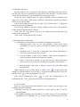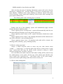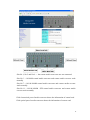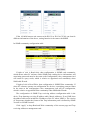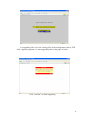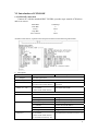
1
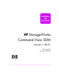
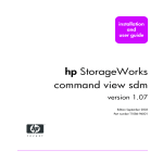
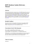
SNMP Management System
User Manual
Version : 5.1.8
Safety Notice
Please read the following items carefully before installing or using this device,
we are not responsible for the damage due to improper use.
The output of this media converter is invisible laser radiation, which may cause
damage to eyes, so do not look to the optical port. Cover the cap when do not
use it.
This is integrated device including delicate components. No vibration or
collision, or there will be damage to structure due. Please uninstall or maintain
this device with the guidance of technical person, also operate according to the
anti-static electronic process.
To protect the stable and safe operation, please ground it carefully when use
it. Please do not take it apart without guidance, or there maybe irrevocable loss
and we won’t be responsible for that.
Content
Chapter 1
Introduction of management system…………………………………….….1
Chapter 2
Instruction for Hardware………………………………………………………..3
I.Instruction for management card………………………………………………….…3
II.Instruction for cascading card………………………………………………….……4
III.Instruction for 10/100M media converter card………………………………….5
IV.Instruction for 10/100/1000M media converter card…………………………...6
V.Instruction for chassis…………………………………………………………………7
VI.Technical Parameters………………………………………………………..…….…8
Chapter 3
Instruction for Software…………………………………………………….….....9
I.Hardware platform and software environment……………………………..….…..9
II.Installation of NMS management software……………………………………......9
III.Introduction of SNMP software………………………………………………....…13
IV.Introduction of WEB software………………………………………………..…....22
V.Introduction of FTP………………………………………………………………...…25
VI.Introduction of CONSOLE……………………………………………………...….27
Chapter 4
Trouble shooting………………………………………………………………..……28
Chapter 1 Introduction of management system
10/100M,10/100/1000M manageable fiber media converters offer a high price/performance
ratio; realize conversion between 10M, 100M, 1000M ethernet electrical port and optical port,
support variety of data rate, SM/MM, single fiber/double fiber, and SFP etc. With simple set-up
and complete function management interface, it supports protocols like SNMP, WEB,
CONSOLE and TELNET, and realizes the integrated management to all chassis.
Functions of Hardware:
* Support 10Base-T, 100Base-TX, 100Base-FX, 1000Base-T
* Meet standards IEEE802.3, IEEE802.3u, IEEE802.3x, IEEE802.3Z, IEEE802.3ah, TS1000
* With high performance auto-sensing exchanging chipset meeting industrial standard, secure
and steady data transmission is ensured with non-traffic jam exchanging performance.
* Chassis supports both 10/100M media converters and 10/100/1000M media converters, and
realizes mixing management of the two kinds of media converters
* 10/100M and 10/100/1000M media converter cards can realize Max.2046bytes packet at
store-and-forward mode, Max. 9K bytes packet at cut-through mode
* AUTO-MDIX at electrical port, convenient for the user
* Standalone chassis with internal special communication power supply, chassis support dual
redundant power supply(support OLP function)
* Fiber media converter module, SFP module, cascading card and NMS card suppot hot plug
Functions of Software:
* Master/slave structure,providing management module (master, slave),
maximum 4 chassis
cascaded can be managed
* Supporting protocols like CONSOLE, WEB, Telnet and SNMP
* Complete system information can be set up and displayed, including the name of the chassis,
terrain information, related information of IP, constant operating time and the versions of the
hardware and soft ware.
* Real time display of voltage and temperature on the cards of the media converters, tempreture
of chassis and report fault in time
* Each port at local or remote devices can be set up or tracked, including the connecting status,
1
connecting speed, half/full duplex, port locked and LFP etc..
* With rate limiting, any rate between 0Mbps and 100M bps can be set at the basic frame of
32Kbps for10/100M media converter card, and any rate between 0Mbps and 1000M bps can
be set at the basic frame of 64Kbps for10/100/1000M media converter card.
* 10/100M media converter cards support management of IP113A/C/F/M, reduce the cost
* 10/100/1000M media converter cards support SFP, CWDM SFP and DWDM SFP, and it can
show the SFP information and digital diagnosis function
* Supporting Link Loopback test, precisely locating the failure, convenient for link test
* Remote power off alarming, precisely distinguish remote failure
* With LFP, quickly locates the failure
* With SNMP protocol, Trap Destination and Community Name and related right can be set up,
real time receive and display of alarming information in way of SNMP Trap,
special
supervising window, bumping alarming information and mail alarming .
* Offering MIB files, convenient to be merged to the third party’s SNMP
* Powerful historical alarming and operating log information tracking and management function
* Flow statistics and Pre-alarming function, real-time display of the communication status at
each port
* Equipment restart, system or module restart by management software, set-up information on
each module will be stored spontaneously when power off
* With graded management mode (common user, super user and administrator)
* Reset to factory set up or dip switch status are optional
* Supporting FTP online upgrading
* NMS support network device auto-sensing and adding
* With centralized management and Top tree, several chassis can be managed in the same
interface at the same time; with grouping management any converter can be conveniently
manipulated among many converters
2
Chapter 2. Instruction for Hardware
I. Instruction for management card
1. Front panel
2.Ports:
ETHER:10/100M RJ45connecting to Internet, management center can manage by WEB, SNMP,
and TELNET through this port
CONSL : standard RS232 for local CLI management
UPLNK: cascading port
3.LED introduction
LED
color
Indication
PWR
Green
ON: power normal
OFF: power abnormal or power down
UPLNK
Green
ON: internet connection normal
OFF: non-connection to Ethernet
FLASH: data transmission
ERR
Red
ON: abnormal(normal with flash for one time when power on)
OFF: normal
4.Buttons introduction
RST: recover to factory default setting(IP Address 192.168.1.251, Sub mask: 255.255.255.0,
Gateway:192.168.1.1)
Notice: Please press RST and insert management card to the chassis when use RST
function. After around 30 minutes, the management card will recover to factory setting.
5. Port connection introduction
5.1
5.2
5.3
ETHER port: When connect to switch/Hub please use Straight-through cable, when
connect to PC card please use Cross-over cable
CONSL port: Please use the matched serial cable(RJ45 TO DB9)
UPLNK port: use standard straight-through or cross-over cable
3
II. Instruction for Cascading card
1. Front panel
2.Ports:
SLAVE: connect to management card or other cascading card
SLAVE : connect to management card or other cascading card
Notice: either port is applicable since they have same function.
3.LED introduction:
LED
Color
Definition
PWR
Green
ON: Normal
LNK
Green
ON: connect to management card
OFF: abnormal
FLASH: chassis in polling
OFF: Disconnection
ERR
Red
ON: Error, wrong chassis No.
OFF: normal
SL1
Green
ON: chassis No. 1
SL2
Green
ON: chassis No. 2
SL3
Green
ON: Chassis No.3
4.Cable connection introduction
Communicate with standard RS485 cable, connector RJ45, transmitting distance can rach
1KM, pls use either straight-through cable or cross-over cable to connect the sub card.
.
5.Switch introduction
There is a switch in the cascading card, used for setting cascading card No.. Please finish
above operation before starting power supply.
Notice: When there are more than one cascading cards, each cascading card
should be setting with different numbers, or there will be clash causing wrong
data transmission.
Cascading card 1
cascading card2
cascading card 3
4
III. Instruction for 10/100M media converter card
1. Outline description:
2.LED indicators
LED
Color
Definition
DUP
Green
ON: FULL Duplex
OFF: HALF Duplex
Flash: clash when working in hall duplex
100M
Green
ON: 100M
OFF:10M
TPLNK
Green
ON: TX Link connected
Flash: data transmission
OFF: TX link disconnected
FXLNK
Green
ON: FX link connected
Flash: data transmission
OFF: FX link disconnected
LFP
Green
ON: LFP enable
OFF: LFP disable
PWR
Green
ON: Normal
OFF: Abnormal
3.Introduction to dip switches
SW1
SW2
SW3
SW4
SW5
SW6
ON
RJ45 port auto negotiation closed
OFF
RJ45 port auto negotiation enable (default)
ON
Half Duplex
OFF
Full Duplex (default)
ON
Connect to 10M
OFF
Connect to 100M(default)
ON
LFP enable
OFF
LFP disable(default)
ON
Remote control closed
OFF
Remote control enable(default)
ON
Cut-through
OFF
Store-and-forward(default)
SW7
NULL
SW8
NULL
Notice:Central media converter module and remote media converter module can be
replaceable as follows:
(Central module)
(Remote module)
5
IV. Instruction for 10/100/1000M media converter card
Outline description:
LED indicators:
LED
Color
DUP
Green
1000M
Green
100M
Green
Definition
ON: FULL Duplex
OFF: HALF Duplex
ON: 1000M
OFF: 100M or 10M
ON: 100M
OFF: 1000M or 10M
ON: TX Link connected
TPLNK
Green
Flash: data transmission
OFF: TX link disconnected
ON: FX link connected
FXLNK
Green
Flash: data transmission
OFF: FX link disconnected
LFP
Green
PWR
Green
ON: LFP enable
OFF: LFP disable
ON: Normal
OFF: Abnormal
Introduction for dip switches
SW1
SW2
ON
Remote control enable(default))
OFF
Remote control closed
NULL
Notice:Central media converter module and remote media converter module can be
replaceable as follows:
(Central module)
(Remote module)
6
V. Instruction for chassis
Front panel
Slot No.1…Slot No.9….Slot No.16
Back panel
Fan
Management card
or cascading card
Power supply A
220V or -48V
Power supply B
220V or -48V
7
VI. Technical Parameters
1. Ethernet port
1)Standards:IEEE802.3, IEEE802.3u, IEEE802.3x, IEEE802.3z
2)Date rate:10Mbps, 100Mbps, 1000Mbps; HALF/DUPLEX auto-sensing
3) Connector: RJ45
4) Connecting cable: UTP CAT5 or UTP CAT5E, transmission distance up to 100m.
2. Fiber port
1)Connector: ST, SC, FC,LC
2)Operating wavelength: MM 850nm 1310nm and SM1310nm 1550nm
3)Connecting fibers: MM: 50/125, 62.5/125, 100/140μm
SM 8.3/125, 8.7/125, 9/125, 10/125μm
3. Optical parameters
Data rate
155m bps
155m bps
155m bps
1.25G bps
1.25G bps
1.25G bps
Distance
20km
40km
80km
20km
40km
80km
TX(nm)
1310
1310
1550
1310
1310
1550
S(dBm)
‹-35
‹-35
‹-36
‹-24
‹-24
‹-23
Pout(dBm)
-14~-8
-4~0
-4~0
-9.5~-3
-11.5~-3
-3~2
4.Working Environment:
Operating Temperature: 0~50℃
Storage Temperature:-10~70℃
Humidity: 5%~90%(non-condensing)
Dimension for rack:315mm (L)×425mm (W)×92mm(H)
Dimension for standalone type: 156mm (L)×128mm (W) ×32mm (H)
AC power: 85VAC~265VAC
DC power: -40VDC~-57VDC
8
Chapter 3. Instruction for Software
I.Hardware platform and software environment
1.Hardware platform
* The hardware platform of NMS is micro server like DELL POWEREGGE 1300, SUN working
station, IPX or more advanced are also applicable.
* System memory is above 64M, 128M is recommended.
* Capacity of hard disk should be over 10G, 20G is recommended for storing vase management
data.
* CPU should be more advanced than Intel PIII 500E, Intel PIII 800EB is recommended.
* 1280*1024 displayer is recommended.
2.Software Environment
* Java environment is set as default while installing NMS, user can use java in the system or
default jre in the installation file. Jre 1.5 above should be used if choose java environment in
the system.
* Mysql should be newer than version 5.0
* Web management supports Netscape4.0, IE5.0 and higher version web browser.
II. Installation of NMS management software
1.MYSQL Installation
Click disk and install MySQL Setup.exe,then click “next” continuously
finish the installation, and pls pay attention to 3 steps:
to
Choose “Manual Selected Default Character Set / Collation”, and then choose
Character Set as “utf8”,then choose“Next”;
9
Choose “Include Bin Directory in Windows PATH”,then click “Next”
Input “New root password” 1234, “Confirm” 1234, and then click “Next”.
Click “Finish” to finish Mysql configuration.
10
2.SNMP Operation
Put the installation disk into CD-ROM driver, then double click setup.exe, then enter the
following interface, and a group of configuration file is provided to help user actively deploy the
software. All configuration files are in contents “resource\config”.
1. Database connection configuration (db.xml)
Configuration files are in contents “resources\config”, including options as
follow:
* driver: always configured as com.mysql.jdbc.Driver
*
url:
connection
string
of
database,
format
:
jdbc:mysql://[ip]:[port]/[database]?autoReconnect=true&useUnicode=true&characte
rEncoding=utf8,substitute IP in the string with installed server IP address of mysql database,
also substitute [port] with server port with mysql database,substitute [database] with nms
database name,database default as nmsdb.
* name: appoint user name for database connection and using, default as root
* password: appoint password for database connection and using, default as1234
* maxidle、maxactive、maxwait is the configuration of database connection pool, operate with the
default setting.
2.SNMP operation configuration (server.xml)
Configuration files are in contents “resources\config”, including configurations
follow:
* trapport:appointed port for receiving alarming and monitoring, default as 62
* maxtrap:Mark the Max. storage for historical alarming record(default as 60000),when
alarming record is over 60000,the oldest alarming record will be deleted automatically.
Trapdel decides the deleting quantity.
* trapdel:Appoint the deleting quantity by the system automatically at one time, default as 5000.
* maxlog:mark the Max storage for system operation log,default as 60000.when the operation
log is over 60000, the oldest operation log will be deleted automatically. Logdel decides the
deleting quantity.
* logdel:Appoint the deleting quantity by the system automatically at one time, default as 5000.
* pollsync:appoint thread pool using in polling of system, thread No defaulted as 8,,less than
the value of thread pool minus 5.
3.Thread pool configuration (server.xhml)
Threadpool under server.xml configures the thread pool of the system. With
advanced thread pool technology in NMS, the capability to deal with software has
been highly advanced. But it does not mean the more thread, the better, so generally
these are not recommended to revise. But user can set the sise of the thread pool
11
according to PC’s property.
* initsize:configure the initial size of thread, default as 15
* maxactive:Configure the Max. enable thread of the system, default as 15
* maxidle:Configure the Max. free thread of the system, default as 15
default set for pollsync mentioned above,is 8,which means 8 of the present 15threadintread
pool are used in polling device. The rest 7 are used for processing other services and
temporary tasks.
4.Interface configuration (gui.xml)
Configuration files are in contents “resources\config”, including configurations
as follow:
* language:Appoint system language, including Chinese and English, indicating English and
Chinese interface respectively. This can be set while logging in the logging interface, or
through “language” under“help”main menu.
* Skin:appoint system interface style,this can be set through“outline”under main menu “help”.
* font:appoint the font in the interface
* size:appoint the size of the characters in he interface
* style:appoint the character style,0 stands for standard, 1stands for thick heavy lines, 2stands
for italic, 3stands for italic thick heavy lines.
5.Device Configuration
In installation contents “resources\config\device”, these files show the
configuration of the devices,no need of revision。
6.Trap rules configuration
Configuration files in contents “resources\config\device” are system Trap rules
configuration files. User can set configuration through “alarming rules” under
“alarming menu” in main interface.
12
III. Introduction of SNMP software
1.Log in
Double click nms.batin installation contents to start system. After initiation
log in interface shows itself automatically as follow:
Notice: the initial super user name is “admin”, and default password is “123”.
2. Adding Node
2.1 Add node manipulating
Choose menu “【configuration】”—> “adding node”, system will pop out
adding node window as follow:
2.1.1Add location node
Choose location page in window, and input location name in the location
input frame. Mark the adding location belongs to which node in the father
node, then click button “Add”, then system will add new location node under
“father node”.
13
2.1.2 Add IP node
Input device name, device model that will be added, master management
card IP address, SNMP port (default as 161), read community (default as public),
write community (default as private), Interval(default 10 seconds),
Timeout((default 5 seconds))
Notice:1.Hereby polling interval means the minimum time interval between two
polling at the same node, default value is 10 seconds.
2.read community of the adding device must be the same as SNMP community
configured in network management card (refer to web management user manual), or system
can not be visited, can not check and change the working status of adding
devices.
2.2 Add node automatically
Choose menu “system”Æ “auto searching”, and see the interface as follow:
14
Search devices automatically
Input the beginning IP, SNMP(default as) Input the initial IP address, SNMP
port (default as 161), overtime time (default value at 2 sec), SNMP read
community (default public) in the interface, then click start. System will find 255
one by one from inputting the initial IP address, like showing in the above
diagram, system will visit 192.168.1.248 to 192.168.1.255 in succeed. If device is
found, device will be added into root node “top tree”.
3. System
3.1 User switching
Input new user name and password in the log-in interface, then confirm. If user
name and password are both right, after confirmation the log-in interface will close
itself, and on the left of the status bar there will be the newest log-in user and user
name.
3.2 User management
User right is divided into 3 grades:
1. System Admin:Super user has all user right.
2. Net Manager:Network administrator, has all other rights except the user
management.
3. Comm User : common user, can only browse system and device
information, cannot revise system data or change device working status.
Notice: Only System Admin can add, delete user.
3.3 Polling
3.3.1 Only after the polling function is started, system will show the status of
the device in time on top tree, and automatically will find chassis, slave
chassis, local and remote media converter under the IP node.
When polling starts, system will automatically visit each IP node in the polling
queue. And there will be chassis nodes via querying results.
3.3.2 Cancel/recover polling of the appointed node
Cancel polling node: choose an IP node in top tree. Then choose
“configuration”Æ “cancel polling”, or click the right of the mouse to choose “cancel
polling” to delete the chosen IP node from the polling queue. Then system polling
will automatically skip this node when polling, and this node’s name will appears as
grey.
Recover polling node: choose an IP node which is not included in the poling
queue, then choose “configuration”Æ “add polling”, or click the right of the mouse
to choose menu“ add polling”. Then add the chosen IP node to the polling queue to
recover polling.
15
3.4 Backup
Choose menu “system”Æ “backup”, system will back up database to
“resources\backup” under installation contents. The format of the backup file is:
[backup time].sql. The backup contents include the structure of the database, all
records in the database (user table, top tree nodes, historical alarming information,
historical operation log and device model No. system supports.)
3.5 Recover
The up of the interface list the backup file in content “resources\backup” under
installation contents. Click “refresh”, file table will be recreated.
Choose a backup file, click “recover”, system will recover database according to
chosen backup files.
3.6 Mib browser
System provides a visual interface for querying SNMP mib files, this function
can be provided to the third party’s network management software application.
Choose menu “alarm”Æ “Mib Browser”, see as below:
3.7Query alarming history
Please choose querying conditions in the up of the window, but alarming time,
operating status, alarming status, class for alarming, NE and number of record are
relations. Alarming time is prerequisite condition, other conditions do not need to be
added to the query conditions if not chosen.。After input query conditions click
“filter”, all tracked alarming information will be displayed in the alarming
information table.
Choose deleting alarming in alarming information table, then click “delete”,
system will delete the chosen alarm from database.
Click “condition delete”, the input query condition will be taken as “deleting
condition”, delete all record that comply with the condition.
Click “store as”, the storing-file dialog box will pop out; all alarm information in
alarming information table will be stored to the appointed file.
Click “reset” to clear the alarming table.
16
3.8 Operation log query
System will store user’s operation log to database, and display all operation log
(for this after log-in) on operation log page in the main interface. Or choose menu
“alarm”Æ “operation log” to track historical operation log record.
On the up of the window there are query conditions choices, including time
range, user. Click “query” after chose a condition, and then the queried log condition
will be seen in the log table.
Choose the deleting record in the log table, click “delete choice” to delete the
chosen record from the database.
Click “delete condition”, the above query condition will be set as the condition
for the operation log that will be deleted.
Click “store as”, store-file box will pop out, and then store the operation log
record to the appointed file.
Click “reset”, the log table will be cleared.
3.9 Alarming rules configuration
3.9.1All alarms are listed in this rule-window, including rules as below:
1. Alarming grades: user can set each alarming’s grade, when alarm
information is received, system will mark its grade as the configured
grade.
2. Alarming voice: if voice file is appointed, when alarm information is
received, system will play the voice file.
3. Pop-out window: if this item is chosen, when alarm information is
received system will pop out a window to remind.
4. Filter: if this item is chosen, system will quit the alarm information
when it receives it, do not store in database or inform in the interface.
5. Mail alarming: if this item is chosen, system will send alarm singal
through mails
When alarming voice is on the status of edition, click “ ” to open choose-file
dialog box, and then choose voice file there. All input the full path of the voice file,
and then click “ ” to play the appointed voice file.
After finish configuration, click “ ” to store the configuration to the
configuration file. Click “ ” to reload rules from configuration files.
3.9.2 Trap Alarm
There are two prerequisites that should be met to ensure the receiving of the
sending alarming information.
1.Alarming receiving IP address should be set the same as that of the PC
operating NMS.
2.The standard alarming port of SNMP is 162. Since system will send alarming
information to PC through 162, so all other Trap monitoring software like
17
SNMPc should be closed before start NMS.
After receiving one piece of alarming information, system will set the class for
alarming by “alarming rules”, and then display it in the device alarming page of the
main interface. Different colors mean alarming in different classes: red means
serious alarming; orange means main alarming; yellow means minor alarming and
green means common ones.
The alarming table in the alarming page is as below:
Double click one of the alarming; system will automatically apply network
element function in right-key menu.
Choose right-key menu “already know”, system will automatically mark the one
who dealt with this alarming record is the current log-in user.
Choose right-key menu “locate to NE”, system will choose related device node
in top tree.
Choose right-key menu “delete”, this alarming information will be deleted, but it
can still be tracked by “query alarming history”.
Choose right-key menu “clear”, all alarming in the table will be cleared, also
alarming can be tracked by “query alarming history”.
3.10 Device setting copy/paste
Choose a media converter node in device top tree, then choose menu
“config”—> “config copy”, or click the right of the mouse to choose menu “config
copy”, system then will copy the chosen media converter’s setting in “media
converter management” interface to memory.
User can choose the media converter node whose setting will be pasted in top
tree (multi-options or one option ) but the type of the chosen node should be the
same as that of the copying device.), then choose menu “set”Æ “paste setting”,
system will set the copied setting to the chosen device one by one.
3.11 Device name management
18
Choose IP node in the interface, then choose chassis, and then click “choose”.
Then system will display all information of local and remote media converters under
the chosen chassis. The name can be edited. After modifying the name of media
converters, click button “restore”, and apply it to top tree.
3.12 Outline
User can choose Metal、CDE/Motif、Windows、Windows Classic independently.
4.Media converter management
From up to down, the diagram shows the main chassis, slave chassis 1, slave
chassis 2 and slave chassis 3. If there is slave chassis, slave chassis status will be
displayed in related place in the diagram. The number on the up of the chassis
diagram indicates the slot No.
Each indicator’s status of the media converters showing in the diagram is the
same as that of the related media converter’s indicators, which is convenient for user
to know the working status directly.
Slot No.1--- The remote media converters are not connected and covered with red
mist
Slot No.3--- For 10/100M media converter, central media converter and remote media
coverter work normally
Slot No.5--- For 10/100/1000M media converter, central media converter and remote media
coverter work normally
19
Slot No.7--- For 10/100/1000M SFP media converter, central media converter and remote
media coverter work normally
Slot No.9--- Remote media converter is taken away(if delete the card, search the card in the
top tree and delet the node)
10/100M media converter management interface
10/100/1000M media converter management interface
20
The device information interface includs two parts: central card information and
remote card information.
Only items on the status configuration panel can be set, basic information and
hardware switch’s status is only for read.
Basic information includs slot position, Model No., full duplex and half duplex,
FX port information, TX port information and optical module information.
Information:
* Port status means opening or closing the Tx port of media converter.
* 10/100M card bandwidth means upstream band width/ down stream bandwidth
value of Tx port, 32K×N;
* 10/100/1000M card bandwidth means upstream band width/ down stream bandwidth value of
Tx port, 64K×N;
* Link test means the test of the integrity of the fiber link.
* Power-down test is to diagnose failure in remote card is caused by power down or
disconnection of fiber link. If remote card can not be found due to power down, then in
“power–down detect” bar of remote card basic information power-down will be shown.
* Click “refresh” to regain from device all configuration and status information of media
converters.
* Click “set” to send configuration of status setting panel to management card, the management
will apply the configuration to the current media converters.
* Click button “reposition” to reposition the media converter, no influence to other devices.
* Click “recover to default setting” will recover the status of the media converters to the initial
setting.
* Click “force to switch setting”, management card will apply the hardware switch setting for Tx
data rate, transmission mode to current media converters.
Notice:
1.Centrol and remote media converters turn on and turn off LFP function
respectively
2. If “REM” switch in local card is set as disable, system can not configure
local and remote media converter. Buttons like “set”, “reposition”, “recover to
default setting”, “force to switch setting” will be in Grey, can not be activated.
21
IV. Introduction of WEB software
1.Loge in
Each main management card has a set of embedded software visited by web,
which is convenient for user visit the rack directly through web page.
Input http://management card’s IP in the address bar of IE browser, then enter
web management log-in interface as below:
(Notice: The IP of all management cards is default as 192.168.1.251)
Click “login” in this page, login window will pop out as below:
Input user name, password; the initial user name is admin and password is 123.
2.System information
After login, the web page will automatically shift to system information page as
below:
22
Slot No.1, No.5 and No.9 --- the remote media converters are not connected
Slot No.3 ---10/100M central media converter and remote media coverter work
normally
Slot No.7 ---10/100/1000M central media converter and remote media coverter
work normally
Slot No.11 ---10/100/1000M
coverter work normally
SFP central media converter and remote media
Click electronical port of media converter shows the information of central card
Click optical port of media converter shows the information of remote card
23
If the 10/100M remote unit connect with IP113S or IP113A/C/F/M, can chen\ck
different information of the above, setting function is the same with SNMP
In SNMP community configuration table
If right of visit is Read Only, then configuration is SNMP read community,
which means when PC software sends SNMP pack reading device information, and
associating password must be the same as the configuration value, management card
will return to query result, which is relative to appointed read community when
NMS adds IP node.
If right of visit is Read Write, then configuration is SNMP Write community. If
when PC software operates on configuration for devices, associating password must
be the same as the configuration value, management card will set configuration,
which is relative to appointed Write community when NMS adds IP node.
The configuration of SNMP Trap receiving address configuration table is the
device Trap alarming receiving IP address table, Max.4 addresses. If use NMS, then
the address table must include the IP address of the PC where NMS is. The version
of Trap means whether the format of the Trap information pack is defined by SNMP
Version 1or SNMP Version2.
Click “apply” to keep Read and Write community of the current page and Trap
receiving address to management card.
24
If choose “delete choice box” on the right of Trap receiving address table, click
“apply.
Click “refresh” to show the latest SNMP configuration information.
V. Introduction of FTP
Software of management can be upgraded online through FTP function. See the
steps as below:
1.input http://management card’s IP/ftp.html in the browser’s address bar to enter
into FTP login interface as below:
Click “login” on the page, and then input user name and password to enter into.
Click “start” to start service, and enter into the page as below:
25
Let upgrading files cover the existing files in the management card by FTP.
click “upgrade programs” to start upgrading and see the page as below:
Click “confirm” to finish upgrading.
26
VI. Introduction of CONSOLE
1. CONSOLE connection
Connect PC with the matched RJ45 TO DB9, open the super termial of Windows
and set as follows:
Baud Rate
Data Bite
Parity
Stop Bits
Flow Control
115200 bps
8
None
1
None
And then restart the PC, input the name and password and see the following information:
2. Description:
Order
Diameter
help(h)
show the system hint
show(s)
check the system information
show card(c)
No. of chassis
(0 refers to the main chassis)
Chassis the information of media
converter
show(s) bw
No. of chassis
(0 refers to the main chassis)
check the band width
creat username
creat new user
del
XXXX
Set
control (c)
Explanation
delete named user
username(u) XXXX
change current user’s name
password(p) XXXX
change current user’s password
writecommunity(w)
set the writing of SNMP
ip( i ) XXXX
set the internet IP address
netmask XXXX
set mask off code
gateway(g) XXXX
set gateway
No. of chassis
(0 refers to the main chassis)
No. of media converter(1-16)
set information of media converter card
27
default(d)
recover to the factory setting
logout
exit
Chapter 4.Trouble shooting
If there are problem when installation like below, please solve them as below:
Failure
Causing
z check the power supply of the chassis, whether card is
PWR indicators OFF after power on
inserted firmly
z make sure the connection cable connects two end
firmly
FXLNK indicator OFF
z Check LFP, if it is ON, then disable LFP
z the transmission rate of media converter does not
match with that of network working device
z fiber connector does not match with transceiver’s port
TPLNK indicator OFF
z fiber link dispassion value is over high, receiving
power is lower than the receiving sensitivity.
z link rate or duplex mode unmatched, please subject to
the recommened connection method.
z Plug head of CAT5 does not connect to RJ45 firmly;
High package loss rate
Fiber connector does not connect to transceiver
firmly
z Wrong configuration of CAT5
Can not see the status of remote z Please make sure the remote control function of local
media converter
media converter enable
Annex: please pay attention to the following items when installation.
1. When to start LFP?
There will be inconvenience even LFP is useful, because after enable LFP, it will
be hard to judge the well connection of TP link. It can be the reason of remote TP
link failure. So we suggest user close LFP when installation media converters, then
user can judge the TO link through link LED. After installation, management center
will start Link Loss function for all.
2. How to configure switch and router?
If all devices connecting to media converters are auto-sensing, then there is no
need to do configuration. When the connecting device does not support auto-sensing,
user has to configure the working mode of the media converter.
(If user’s device working in fix rate, and media converter works in auto-sensing
mode, media converter will auto sense to the mode of half duplex causing abnormal.)
28