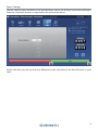
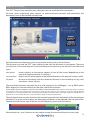
1
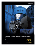
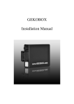
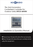
Stereoscopic Calculator cev.fr User Manual English Standard Version 1.0 Before using this product, please read the instruction carefully and keep this manual for future use. Introduction The “STEREOTEC Stereoscopic Calculator” enables you to find settings for your 3D Rig. Just type in a few parameters (like distances in the set or the kind of camera and lens you use) and the Stereoscopic Calculator will calculate possible settings of the interaxial (interocular) and the angulation (convergence). With this tool stereoscopic recording gets convenient - “Don’t guess any more, calculate!” The manufacturer of this product is: stereotec - Stereoscopic Technologies GmbH Ahornstr. 5 82205 Gilching Germany www.stereotec.com Please find further information and news on http://www.stereoscopic-calculator.com/ or send an e-mail to [email protected]. Concerning any service and warranty requests, please contact your distributor first or send an email to [email protected]. PLEASE NOTE THAT WE CANNOT PROVIDE A FREE SHOOTING CONSULTING FOR 3D-QUESTIONS. BUT: If you like to know more about 3D from an artistic or technical point of view we highly recomment our 3D courses. More information can be found on www.stereotec.com What’s in the Box? ●● CD-ROM with the STEREOTEC Stereoscopic Calculator software and manual ●● USB-Dongle (required for using the software) Contents Introduction............................................................................................................................................................Page 2 Manufacturer Information.................................................................................................................................Page 2 What’s in the Box?.................................................................................................................................................Page 2 Disclaimer................................................................................................................................................................Page 3 Installation and Start............................................................................................................................................Page 3 Overview..................................................................................................................................................................Page 4 Getting started.......................................................................................................................................................Page 5 General Settings....................................................................................................................................................Page 9 Adjust Scenery.................................................................................................................................................... Page 10 Glossary................................................................................................................................................................. Page 11 2 Installation and Start 1 Make sure the Serial on the CD-ROM is the same as on the USB-Dongle 2 Copy the folder on the CD-ROM onto your hard drive (e.g.: C:\Program Files\) 3 Plug in the USB-Dongle in a free USB-Port 4 Double click on ‘Stereoscopic_Calculator.exe’ in the new folder on the hard drive to start the application Disclaimer STEREOTEC - Stereoscopic Calculator Agreement Please take a minute to review the licensing terms below. Click the accept button to accept the licensing terms and proceed to run the Stereoscopic Calculator. If you do not accept the terms you are not entitled to use the software. Electronic End User License Agreement This is a contract. By installing or executing this software you accept all the terms and conditions of this agreement. If you do not agree to the terms of this agreement, click in cancel to exit this program. This Stereoscopic Technologies GmbH (hereinafter “Stereotec”) End User License Agreement accompanies the Stereoscopic Calculator executable software. Stereotec grants to you a nonexclusive license to use the software, provided that you agree to the following: Use of this package is governed by the following terms: 1. Grant of license Node-locked license: Stereotec grants you as a company the right to install and use the software on the computers specified in your license arrangement with Stereotec. Installing is the process of storing the program code on a hard disk. Using is defined as loading the program from disk to ram. The number of hard disks where this program is installed must not exceed the number speci-fied in your license file and the program may only be used on the physical computer specified in the license file. 2. Copyright The software is owned by Stereotec or its suppliers and is protected by European Union, United States and international copyright laws, international treaty provisions, and all other applicable national and international laws. Therefore, you must treat the software like any other copyrighted material (books, films). You may not sell or rent this software. You may not distribute the software in any form. 3 3. Other restrictions You may not modify, rent, resell, distribute or transfer your rights to the use of the software under this Stereotec License Agreement. You may not reverse engineer, decompile or disassemble the software. Any transfer must include the most recent update and all prior versions. 4. Liability Stereotec is liable for any negligent or deliberate violation of the contractual main obligations (cardinal obligations), especially for a violation that would negatively affect the purpose of the contract, undermine the essential rights of the Client or the essential obligations of the Stereotec as well as violate any obligations that make possible a proper management of the contract in the first place. Incidentally Stereotec is solely liable for willful or grossly negligent behavior on the part of Stereotec, its legal representatives or vicarious agents. This also applies to all cases of impossibilty, default, positive contract violation, tortious claims as well as fault upon conclusion of the contract. The liability of Stereotec for compensations is limited to the calculable damages as per standard contract provisions unless Stereotec is liable due to grossly negligent or deliberate violation of contractual main obligations (cardinal obligations). 5. Warranty exclusion Stereotec supplies this software “AS IS” without any warranties of any kind to the maximum extent permitted by applicable law. This software calculates an estimation for a maximum interaxial for stereoscopic shooting by using certain parameters. Almost all of these parameters are put in into the calculator by the user. As the parameters used to calculate can vary itself in accuracy or can be an approximation, the calculated result may vary as well in accuracy. By running this software you agree, that this software can only provide an approximation for a maximum interaxial. You agree that the results calculated are just for approximate information purposes and don’t have any guaranty for accuracy. We exclude any liability for using these calculated results. It is the liability of the user to check if these values are appropriate for the setting of the 3D parameters or not. No warranties - to the maximum extent permitted by applicable law, Stereotec disclaims all warranties, either express or implied, including but not limited warranties of merchantability and fitness for a particular purpose, with respect to the software, the accompanying product manual(s) and written materials. 6. Applicable law This agreement is governed by the laws of the Federal Republic of Germany. 4 Overview 1 2 3 4 5 6 7 Description 1 Titlebar-buttons to get direct access to help, info, updates, minimize, maximize and close 2 Tabbar-buttons to get fast access to the modification of scenery-setup, camera, lens, screen, focus and general settings 3 Main screen 4 Save as and Open 5 Information about the opened file, the chosen camera-type and lenses and warnings of wrong or missing input parameters 6 Calculated result of the interaxial distance (in mm) and the angulation (in steps). Above all + and - buttons to change the interaxial distance in mm-steps. 7 Interaxial Control-Bar with the maximum interaxial range of the 3D Rig and the calculated interaxial distance 5 Getting started To learn something about the mode of operation, it is useful to do some elemental settings before adjusting the set (scenery). Camera Settings As a first basis for the calculation choose the camera model you plan to use for the film production: In the field “BRAND” you can choose between “predefined sensor size” with stored values for sensor sizes and “custom sensor size”, where you can type in any sensor size in mm (horizontal active sensore size needed) by using the field “TYPE”. In later upgrades (optional) there will be complete camera types available with more accurate data. (This will make the calculation more accurate.) You can store up to five sensor sizes for a fast switching with the radio buttons. The active model below “USE” will be used for the calculation. 6 Lens Settings As second basis for the calculation choose the lens type you plan to use for the film production: In this version, choose “custom” in the field “BRAND” and “variable” in the field “TYPE”. Then enter the focal distance in the field “SIZE” (input in mm). VERY IMPORTANT: You have to enter the right focal length in regard to the sensor size. That means, if you’re using e.g. a 10 mm Digiprime, the focal length printed on the lens is calculated for a 2/3 inch sensor, to be exacly a 10 mm lens. In any other case (e.g. you’re using a lens that was not originally designed for your sensor), you have to convert the value into the equivalent in regard to the sensor size - otherwiese the result of the calculator will be wrong! (It is planned to provide further brands and types as optional upgrades - but the testing and data collection needs a lot of time - so please stay tuned) You can store up to five lenses or maybe five zoom values for a fast switching with the radio buttons. The lens value, switched on by clicking the radio button below “USE” will be used for the calculation. 7 Screen Settings As a third basic value for the calculation choose the maximum (realistic, not the exception) screen size (width) used later in the theaters where you plan to produce your footage for: If the final screen width could not be appraised exactly, use a broader value. For example a possible value for cinemas could be a value between e.g. appr. 8 m to 12 m (appr. 26 ft to 40 ft) and for 3d monitors could be a equivalent of e.g. appr. 3 m to 4 m (10 ft to 13 ft). Please note that you cannot put in values smaller than 3 meters (10 ft). This is a function for your own safty, because if you shoot for 3d monitors you should not go lower than 3 meters with the screen size for the calculaton. If you’re unsure what to use, just make a test shoot and try it. Testet and adoptend values for monitors will be available in future as an (optional) upgrade. But don’t take these values as a law. It’s the sole decision of the stereographer. In case of a lot of different screen sizes actually used, it could be a good information to choose a broader value as standard practice - By the way: Stereoscopic Technologies GmbH is currently developing a solution for the problem of different screen sizes. If you’re interested just contact us by email [email protected] Hint: Afterwards it’s easier to switch from a larger screen to a smaller one than vice versa: The reason is, that a 3D-movie, which is presented on a big screen, but was originally produced for a small screen, might most likely exceed the limits of human vision. If the 3D-movie, which was produced for a big screen, will be shown on a small screen, the 3D effect will be just shallower, which is better than exeeding the limits of human vision. If you want to know more about this, we recomment our 3d workshops. More information can be found at www.stereotec.com 8 Focus Settings The last value for the calculation is the focal distance, means the distance to the focused object. Enter the same focal distance as adjusted on the real camera lenses: Please note that you will see only any difference in the calculation if the focal distance is quite short... 9 General Settings In the Settings-Tab you can choose the unit of measurement (metric or inch/feet) and set some basics of perception, like eye separation or the maximum screen parallax: The average eye separation of adults are appr. 63 mm (appr. 2,5 inch). When the “max. pos. screen parallax” has the same value as the “eye separation” the filmed object at the far plane is perceived as a point at infinity. When you record an object in a closed room it might be useful to set the value of the “max. pos. screen parallax” to a smaller value than the eye separation. But again, this is the sole decision of the stereographer. With the “max. neg. screen parallax” you can influence the limit for how far an object pokes out of the screen - that means in this example in the screenshot above, that an object comes out almost 2/3 towards the viewer; that means, if the viewer is sitting e.g. 9 meters away, the object will be seen at appr. 3 meters in front of the viewer. Please don’t forget to enter the maximum possible interaxial in mm or inch that you have available with your own 3d rig - this will adopt the length of the control bar on the bottom. Attention: Changing the “unit of measurement” to “inch/feet” has no influence to the display of “INTERAXIAL” and “ANGULATION” on the right side! These values are always displayed metric in mm (INTERAXIAL) and respectively steps (ANGULATION). 10 Adjust Scenery The “SET”-Tab you may need the most, after you have set up all the other parameters. For each scene, respectively every camera- or actor-movement (towards and backwards), the parameters have to be checked and adjusted: Each measurement references to the sensor-plane in the camera, not to the lens! The distances put into the “SET” have nothing to do with the distances in the theatre. These are just distances in the recording set! Two of the distances are necessary, the third will result from the input. near plane screen plane far plane nearest objects to the camera, appear in front of the screen (depending on the setting of negative parallax in “settings”) objects on this plane appear to be located directly on the physical screen surface distance to the object with the maximum distance in the recording set (e.g. wall, mountains, moon, infinity) The calculated maximum interaxial (in mm) and angulation (in millidegree - so e.g. 0032 means 0.032 degree) can be seen directly on the right side of the calculator. PLEASE NOTE THAT THE INTERAXIAL AND THE ANGULATION IS FOR ORIENTATION ONYL. (Reason: Values put into the calculator are sometimes not accurate enough or the meachanics of the rig or the camera or the calibration is not exact enough. But the convergence can be controlled on a 50%-overlayed picture of both streams! You will see the right angulation setting when an objekt in the screen window distance creates no double images in the overlayed picture). The calculated values are also shown in the interaxial control-bar at the bottom of the stereoscopic calculator. For some artistic aspects the perception of depth can be reduced with the control bar. Therefor the left camera icon in the bar can be shifted very easily with the mouse. Alternatively the + and - buttons can be used to change the interaxial distance in mm steps. 11 Glossary accommodation focussing of an observed point angulation resulting angle spanned between the optical axes of the two cameras autostereoscopy seeing a picture three dimensional without additional utilities (glasses) binocular with both eyes convergence to pivot both optical axes to an observed object depth cues information about the depth of a scene; there are monocular depth cues like perspective and binocular depth cues like stereopsis deviation parallactic displacement of corresponding points on two 3D-exposures (left and right image) disparity distance of two corresponding points on the retina far point the farthest point from the nodal point of the camera Fovea Centralis area of the sharpest vision on the retina Horopter set of points for which the light falls on corresponding areas in the two retinas interaxial (distance) distance of the center-points of the two camera lenses interocular distance distance of the center-points of the eyes monocular with one eye motion parallax change of angular position of two stationary points relative to each other as seen by an observer, caused by the motion of an observer near point the nearest point from the nodal point of the camera nodal point point about which a lens is rotated where close and distant subjects focused on the film plane maintain their relative positions to one another Panum’s fusional area region of binocular single vision parallax change of angular position of two stationary points relative to each other as seen by an observer. If there is no parallax between two objects then they occupy the same position. pseudoscopy inversion of the spatial impression screen plane (window) image plane mapped directly on the surface of the screen screen parallax distance of two corresponding points on the screen surface stereopsis ability to make fine depth discriminations from parallax provided by the two eye’s different positions on the head 12 Copyright by stereotec - Stereoscopic Technologies GmbH 2009 www.stereotec.com