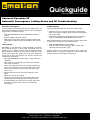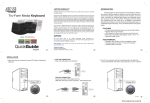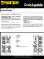
1
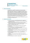
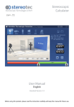
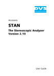
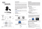
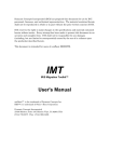
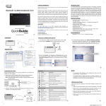
Quickguide
Software Version 3.9.21 / May 2011
Advanced Operation 3D
camin Preparation
1. Mount camin to camera or 3D rig.
Make sure, all cables can be connected without strain. Mount
motors on lens support rods.
2. Connect motor cables for focus, iris, zoom, convergence & interaxial to camin.
All cmotion cables are color coded. Cables with green sleeves
are motor cables. Connect the focus motor cables to Motor 1 &
Motor 3 (Focus & Iris), iris motor cables to Motor 2 & Motor 4,
zoom motor cables to Motor 5 & Motor 6, convergence to Motor
8 and interaxial to Motor 7.
3. Make sure antenna is connected to the camin.
If you need to use your cvolution system in cable mode, use a
CBUS cable. Be aware that there are different models of CBUS
cables. Plugs with orange sleeves match the 8 pin Lemo connector of the camin 8M and newer cdisplays. Plugs with blue
sleeves match the CBUS sockets found on older camin, cfinder
and older cvolution & cooperate units.
4. Connect camin to camera (or power supply) using a
RS- or EXT cable.
Depending on your camin model, there might be more than one
RS-receptacle. If there is more than one RS-socket, always use
the rightmost socket to power the camin. Never power more
than 4 motors from one RS-socket. For 8 motors, you need two
sufficiently dimensioned power supplies to feed the RS-sockets.
5. Set the desired RF channel with the small dial below
the antenna.
NOTE: „0“ turns off RF reception.
6. Switch camin on.
If the power switch is in position „I“, motors are powered by the
supply voltage. If switch is in position „II“, voltage is boosted to
26 V for higher motor speed, at th e cost of higher c urrent draw.
Make sure your camera/ power supply is capable of delivering
about 1,1 A per motor connected for 12 V operation.
camin 2M/4M/8M
a) Antenna
b) Channel dial
c) RF LED
d) ON LED
e) Power Switch
f) Motor 1 - Motor 6
g) USB port
h) Motor 7-8
i) RS-1
j) RS-2
k) CBUS
l) EXT-1
m) EXT-2
NOTE: The illustration shows a camin
8M. The camin 2M and the camin 4M
have respectively fewer motor outlets.
cmotion Mechatronikentwicklungs- und HandelsgmbH
Schanzstrasse 41/1 | 1140 Vienna, AUSTRIA
phone +43 1 789 10 96 | www.cmotion.eu | [email protected]
Quickguide
Software Version 3.9.21 / May 2011
Advanced Operation 3D
hand unit Preparation
1. Put a battery in each cvolution hand unit and switch
hand unit on.
NOTE: When the RF channels of camin and cvolution hand unit do
not match, the hand unit will not be able to connect to the camin
and shut down after 6 sec. To prevent this press „Select“ twice to
enter the menu.
NOTE: Make sure that you do not touch the zoom controller while
powering the hand unit since the controller calibrates itself during
power up.
For 8 channel operation, you need two hand units, one for the
focus puller, one for the stereographer.
2. Whenever you start working with a cvolution system,
it is advisable to reset the unit to factory defaults.
The factory defaults can be found in the MAIN menu. You can
enter the menu by pressing the scroll wheel („Select“) of the
hand unit twice. Scroll down to „Factory Settings,“ press „Select“, confirm by pressing „Select“ again. Now the factory settings are active.
Repeat this step for both hand units.
4. Assign motors
On the first cvolution hand unit (for the focus puller):
wEnter the menu by pressing „Select“ twice. Scroll down to
„Knob“ and confirm by pressing „Select“. If you reset the hand
unit, the knob scale should be assigned to focus. If not, select
„Scale“, scroll to „Focus“ until it‘s highlighted and confirm your
selection again by pressing „Select“. Press the „LENS“ Button
to go back and enter the „Slider“ menu. Set Scale to „Iris“. Confirm and go back to the menu.
Now configure the cvolution hand unit for the stereographer:
Enter the menu by pressing „Select“ twice. Scroll down to
„Knob“ and confirm by pressing „Select“. If you reset the hand
unit, the knob scale should be configured for focus. Select „Scale“, scroll to „Conv(ergence)“ until it‘s highlighted and confirm
your selection again by pressing „Select“. Press the „LENS“
Button to go back and enter the „Slider“ menu. For „Scale“, select „Interax(ial)“ now. Confirm and go back to the menu.
In the factory settings, the knob controls focus and the slider
controls the iris. Zoom is controlled by the cvolution zoom module.
5. Calibrate motors by pressing „CAL“ for 3 seconds.
3. Set the correct RF Channel for BOTH cvolution hand
units (if necessary).
6. Quick syncing two motors
Enter the MAIN menu (see above) und select RF Channel. Now
use the scroll wheel to select appropriate channel and confirm
your selection by pressing „Select“.
If you experience RF problems, try another RF channel. You
can also try to boost the RF power by selecting „Rf Power“ in
the MAIN menu. Be aware that when the camin is very close to
the cvolution hand unit, too much RF power will result in bad
reception. In this case, reduce „Rf Power“ in the MAIN menu.
NOTE: You can calibrate an axis seperately by pressing „CAL“
and „LENS“ on the focus knob, slider or zoom controller.
If you need to set a lens offset quickly to sync two motors, go
to the menu and assign „Marker“ to the red or green RUN button. Now, while pressing down the „Marker“ button, adjust the
desired axis with the respective controller.
Please refer to the user manual for more information on setting
lens offsets.
cvolution hand unit
a) advanced knob
b) MENU WHEEL („select“)
c) KNOB button
d) LENS button
e) RUN button
f) slider
g) Zoom controller
h) Zoom menu
cmotion Mechatronikentwicklungs- und HandelsgmbH
Schanzstrasse 41/1 | 1140 Vienna, AUSTRIA
phone +43 1 789 10 96 | www.cmotion.eu | [email protected]
Quickguide
Software Version 3.9.21 / May 2011
Advanced Operation 3D
Scale Sync, Save/Load User Settings
Scale Sync
Save/Load User Settings
The SYNC sub-menu allows you to create up to 32 offset values for each axis on a pair of lenses or other scales. Individual
lenses, especially zoom lenses, vary in their scale precision and
scale limits. SYNC enables the perfect synchronization of two
lenses for stereoscopic shooting.
Using the camin‘s USB port you can quickly and easily save/
load user settings. This enables to you to have your personal
settings on every cvolution system you use.
NOTE: 2 motors must assigned to the same function before you
begin, e.g. both Motor 1 and Motor 2 are set to Focus.
• Enter the MAIN MENU, scroll to “User Settings“ and press
select.
• Select “save“ and press “next“
• Select one of the slots, e.g. “User1“ and press “Select“
• Wait for “Data successfully written to USB” and press “exit”.
This example shows how to sync Focus on a pair of lenses.
• Select SYNC from the MAIN menu and press “Select”.
• Select FOCUS SCALE and press “Select” again.
• The SYNC FOCUS screen will open and the Master focus
motor position will be displayed here.
• Turn the knob so that the master focus scale is set to its
closest focal distance.
• Turn the MENU WHEEL to independently adjust the Slave
focus motor to the same value
• Press “save” to store the sync point. The number of saved
offset points will be displayed.
• Repeat steps the last three until you have created an offset
for each value.
After saving Sync Points you can check your matches to ensure
sufficient precision.
•
•
•
•
•
In the Sync Scale Menu, press “check”.
Turn the MENU WHEEL to scroll through the saved points.
Both motors will turn to their new synchronized positions.
You can delete an individual offset by pressing “clear“.
Press “back“ to return to the pervious screen.
From the initial page, you can select another scale to synchronize. You can clear each Scale individually by deleting all sync
points on a scale or you can clear all Scales at once.
To save settings:
To load settings:
• Enter the MAIN MENU, scroll to “User Settings“ and press
select.
• Select “load“ and press “next“
• Select one of the slots, e.g. “User1“ and press “Select“
• Wait for “Data successfully loaded
from USB” and press “exit”.
NOTE: You cannot load empty settings.
NOTE: Currently, only camin settings are saved. This includes:
Motor Assignment, Direction, Torque, Ramp and Scale Sync/
Scale Link.
So, if you want to, for example, save Scale Sync for a pair of
lenses proceed as follows:
•
•
•
•
•
Sync your first lens pair as described above.
Save your settings to a user settings slot.
Clear Scale Sync.
Sync your second lens pair.
Save the settings to another slot.
• You can delete all of the offset points by selecting CLEAR
ALL.
• Confirm by pressing “yes”.
NOTE: If you reset the camin to factory defaults, you will also be
asked whether you want to clear all sync points.
cmotion Mechatronikentwicklungs- und HandelsgmbH
Schanzstrasse 41/1 | 1140 Vienna, AUSTRIA
phone +43 1 789 10 96 | www.cmotion.eu | [email protected]
Quickguide
Software Version 3.9.21 / May 2011
Advanced Operation 3D
Mirror Rig Setup
1. cvolution system 3D Setup for Mirror Rigs
The following instructions show you how to set up your cvolution
system for use with your choice of mirror rig. After successful setup, your hand unit display will directly read out correct
Interaxial and Convergence/Screen Plane distance values.
NOTE: Starting from software version 3.9.15 on the hand unit and
3.9.19 on the camin it is possible to control the following 3D rig
axes: Interaxial, Convergence, Mirror, Tilt and Rotation. The availability of these axes depends on the manufacturer and type of
your 3D rig.
1.1 camin Setup
• Connect the motors driving the rig to your camin.
• Make sure no cables are under strain.
• Connect the motor for Interaxial to motor port M7,
Convergence to M8.
NOTE: On advanced 3D rigs you can control more 3D axes, such
as Mirror or Tilt. These do not have dedicated motor ports on the
camin. Connect these to any available motor ports and assign accordingly via the hand unit Motor menu.
1.2 stereographer hand unit Setup
To assign Convergence to the hand units knob and Interaxial to
the slider follow these steps:
• Enter the MAIN MENU by pressing „Select“ twice.
• Scroll down to „KNOB“ and press „Select“.
• Scroll to “SLIDER” and press „Select“. Set the Slider Scale
to Interaxial and the Direction to right.
• Return to the MAIN MENU and enter “DIRECTION” and
make sure M7 and M8 direction is set to right, or depending on the motor mount, left.
• Return to the MAIN MENU. Press „Exit“. Calibrate Interaxial and Convergence by pressing and holding „CAL“ for 3
seconds.
NOTE: To move from minimum to maximum by a clockwise knob
rotation set Knob direction to left. To move in a counter-clockwise
rotation set the direction to right.
1.3 Setting the Zero Point
1.4 Setting Convergence/Interaxial Scaling
NOTE: Depending on the rig you use, some of the following instructions might not be feasible to use. Contact us or your 3D
manufacturer for more information on the best calibration method
for your rig.
1.4.1 Setting Convergence/Interaxial Scaling by Calibration Range
NOTE: Make sure your Convergence/Interaxial axes are properly
calibrated.
• Scroll to „3D MENU“ and press „Select“.
• Scroll to „Conv Scaling“ or „Interax Scaling“ respectively
and enter.
• Select „Cal Ran“ and press „Next“. Enter the Interaxial
Distance Range in mm or the Convergence Angulation
Range in degrees. Press „save“.
1.4.2. Setting Convergence/Interaxial Scaling by Factor
NOTE: Make sure your Convergence/Interaxial axes are properly
calibrated.
• Scroll to „3D MENU“ and press „Select“.
• Scroll to „Conv Scaling“ or „Interax Scaling“ respectively
and enter. Select „Factor“ and press „Next“.
• Enter the scale factor for your 3D rig (to obtain this factor
please contact your rig manufacturer). Press „save“.
1.4.3 Setting Convergence Scaling by Target
• Enter the MAIN MENU. Scroll to „3D MODE“ and press
„Select“.
• Scroll to „Conv Scaling“ and press „Select“. Select „Target“
and press „Next“.
• Looking through the stationary camera place a object dead
center in your viewfinder. Now set Interaxial to its maximum.
• Looking through the second camera adjust Convergence
until the object is also centered in this cameras viewfinder.
• Now measure the distance to the object and enter the
value. Press “Save“.
NOTE: For best results use a distance of at least 5m/15ft.
To configure properly your rig you must first line up both cameras on your rig in such a fashion that they both show precisely
the same 2D image.
• Line up both cameras on your rig. Make sure they both
show precisely the same 2D picture.
• Enter the MAIN MENU by pressing “Select” twice.
• Scroll to and enter “3D MODE” by pressing “Select”
• Select “Zero Point” and press “Select”
• Confirm by pressing “Yes”
cmotion Mechatronikentwicklungs- und HandelsgmbH
Schanzstrasse 41/1 | 1140 Vienna, AUSTRIA
phone +43 1 789 10 96 | www.cmotion.eu | [email protected]
Quickguide
Software Version 3.9.21 / May 2011
Advanced Operation 3D
Automatic Convergence, Linking Scales and 3D Troubleshooting
Automatic Convergence
Troubleshooting
In some stereoscopic shooting situations you might want to set
the screen plane distance directly instead of the Convergence
Angle. To do so, follow these steps:
If your experience trouble take a look at the steps below.
• Enter the MAIN MENU, scroll to “3D MODE” and press
“select”.
• Scroll to “Mode” and select “AutoC”.
• Now set the screen plane distance directly instead of the
Convergence Angle using your Convergence axis controller.
Linking Scales
Depending on job demands it might sometimes be advisable to link 3D rig axes to Focus and concentrate solely on
pulling Focus. In another scenario when using Zoom lenses,
Mirror, Rotation and Tilt axes can be used to match two lenses
exactly and correct their nodal point and other differences.
To link one or more slave axes to your choice of master axis
complete the steps below.
• AutoConv: If you can set the screen plane, but the angle
does not change accordingly, make sure you have properly
set the zero point.
• Interaxial/Convergence: If the display shows an inverted
value, try changing the Motor Direction for that axis.
If the problem persists, reset you system to Factory Preset and
re-setup as per instructions. To reset the system:
• Enter the MAIN MENU, scroll to “MAIN”.
• Enter and select “Factory Settings”. Press “select” and
confirm by pressing “select” again
Contact cmotion if any of these instructions fail to solve your
problem. Have your system components‘ serial numbers and
software versions at hand when contacting us.
• Enter the MAIN MENU, scroll to “Sync”. Enter and select
“SCALES”.
• Now select the scale (master) you want to synchronize
other scales (slaves) to.
• Press “next”. Select the slaves by scrolling and pressing
“select”. The selected scales will turn green. Press “next”.
• Set the first sync point on your master and slaves axes.
Press “save”.
• Set the next sync point on your axes and press “save”
again.
• Repeat for up to 32 sync points.
• Check your saved sync points by pressing “select” and
cycle through your saved sync points using the wheel.
• To unlink linked scales and clear sync points enter “Sync”
and select “Clear All”, press “Select” and confirm by
pressing yes.
cmotion Mechatronikentwicklungs- und HandelsgmbH
Schanzstrasse 41/1 | 1140 Vienna, AUSTRIA
phone +43 1 789 10 96 | www.cmotion.eu | [email protected]