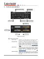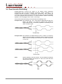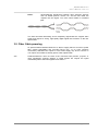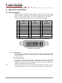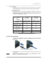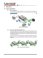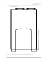
1
User's Manual DA2DVI-HDCP-Pro Page 2 / 38 DA2DVI-HDCP-Pro User’s Manual – Rev. 1.0 SAFETY INSTRUCTIONS Class II apparatus construction. This equipment should be operated only from the power source indicated on the product. To disconnect the equipment safely from power, remove the power cord from the rear of the equipment, or from the power source. The MAINS plug is used as the disconnect device, the disconnect device shall remain readily operable. There are no user-serviceable parts inside of the unit. Removal of the top cover will expose dangerous voltages. To avoid personal injury, do not remove the top cover. Do not operate the unit without the cover installed. The apparatus shall not be exposed to dripping or splashing and that no objects filled with liquids, such as vases, shall be placed on the apparatus. The apparatus must be safely connected to multimedia systems. Follow instructions described in this manual. WEEE (W as te E lec tr ic a l & E lec tr on ic Eq u i pm ent) Co rr e ct Di spo s al of T his P rodu ct This marking shown on the product or its literature, indicates that it should not be disposed with other household wastes at the end of its working life. To prevent possible harm to the environment or human health from uncontrolled waste disposal, please separate this from other types of wastes and recycle it responsibly to promote the sustainable reuse of material resources. Household users should contact either the retailer where they purchased this product, or their local government office, for details of where and how they can take this item for environmentally safe recycling. Business users should contact their supplier and check the terms and conditions of the purchase contract. This product should not be mixed with other commercial wastes for disposal. Page 3 / 38 DECLARATION OF CONFORMITY We, Lightware Kft. 1071 Budapest Peterdy str. 15 HUNGARY as manufacturer declare, that the products DA2DVI-HDCP-Pro ( DVI Distribution Amplifier ) in accordance with the EMC Directive 2004/108/EC and the Low Voltage Directive 2006/95/EEC are in conformity with the following standards: EMI/EMC ..................................... EN 55022 Class B Safety........... UL, CUL, GS, CR, RCM, PSE, Class II Date: 01 August 2011 Name: Gergely Vida ( Managing Director ) Signed: Page 4 / 38 DA2DVI-HDCP-Pro User’s Manual – Rev. 1.0 Table of contents 1. INTRODUCTION ............................................................................................................................................ 6 1.1. 1.2. 1.3. BOX CONTENTS ......................................................................................................................................... 6 DESCRIPTION ............................................................................................................................................ 6 FEATURES ................................................................................................................................................ 7 2. CONTROLS AND INDICATORS ................................................................................................................... 8 3. TECHNOLOGIES ......................................................................................................................................... 10 3.1. 3.2. 3.3. 3.4. 3.5. 4. UNDERSTANDING EDID ........................................................................................................................... 10 COMMON PROBLEMS RELATED TO EDID .................................................................................................... 11 ADVANCED EDID MANAGEMENT ............................................................................................................... 11 PIXEL ACCURATE RECLOCKING................................................................................................................. 12 FIBER CABLE POWERING .......................................................................................................................... 13 ELECTRICAL CONNECTIONS ................................................................................................................... 14 4.1. DVI CONNECTORS ................................................................................................................................... 14 4.1.1. DVI output .................................................................................................................................... 14 4.1.2. DVI input ...................................................................................................................................... 15 4.2. DC +5V CONNECTION ............................................................................................................................. 15 5. OPERATION ................................................................................................................................................ 16 5.1. TYPICAL APPLICATION .............................................................................................................................. 16 5.1.1. EDID management ...................................................................................................................... 16 5.1.2. Cascading multiple DA2DVI-HDCP-Pros ..................................................................................... 16 5.2. POWERING ON ........................................................................................................................................ 17 5.3. ABOUT EDID MEMORY ............................................................................................................................. 18 5.4. SWITCHING THE EDID ............................................................................................................................. 19 5.5. LEARNING THE EDID ............................................................................................................................... 19 5.6. HDCP MANAGEMENT .............................................................................................................................. 20 SOFTWARE CONTROL – USING LIGHTWARE MATRIX CONTROLLER ................................................ 21 6. 6.1. INSTALLING THE MATRIX CONTROLLER SOFTWARE ...................................................................................... 21 6.2. ESTABLISHING THE CONNECTION ............................................................................................................... 22 6.3. CONTROL MENU ...................................................................................................................................... 23 6.4. INPUT SETTINGS...................................................................................................................................... 24 6.4.1. HDCP key counter ....................................................................................................................... 24 6.5. OUTPUT SETTINGS .................................................................................................................................. 25 6.6. EDID MENU ............................................................................................................................................ 26 6.6.1. EDID operation ............................................................................................................................ 26 6.6.2. Advanced EDID Editor ................................................................................................................. 28 6.6.3. Easy EDID Creator ...................................................................................................................... 29 6.7. TERMINAL MENU ...................................................................................................................................... 29 6.8. STATUS MENU ......................................................................................................................................... 30 6.9. FIND MENU ............................................................................................................................................. 30 7. FIRMWARE UPGRADE ............................................................................................................................... 31 8. TROUBLESHOOTING ................................................................................................................................. 33 8.1. 8.2. 8.3. 9. GENERAL PROBLEMS ............................................................................................................................... 33 PICTURE IS NOT DISPLAYED OR DISTORTED ................................................................................................ 33 HDCP ISSUES ........................................................................................................................................ 33 SPECIFICATIONS ....................................................................................................................................... 34 9.1. MECHANICAL DRAWINGS .......................................................................................................................... 35 9.1.1. Front view .................................................................................................................................... 35 9.1.2. Rear view ..................................................................................................................................... 35 9.1.3. Top view ...................................................................................................................................... 36 9.1.4. Bottom view ................................................................................................................................. 37 10. VERSION APPLICABILITY...................................................................................................................... 38 11. WARRANTY ............................................................................................................................................. 38 12. DOCUMENT REVISION HISTORY .......................................................................................................... 38 Page 5 / 38 1. Introduction Thank you for choosing Lightware DA2DVI-HDCP-Pro, the two output professional DVI distribution amplifier supporting HDCP encryption and HDMI 1.3a compliant signals. 1.1. Box contents DA2DVI-HDCP-Pro User’s manual Quick Start Guide +5V plug-in power adaptor 1.2. Description Lightware DA2DVI-HDCP-Pro is a multifunctional distribution amplifier with built-in EDID Management and Pixel Accurate Reclocking, supporting DVI and HDMI 1.3a signals with or without HDCP encryption. It automatically compensates for up to 60 meters of DVI copper cable, hence no adjustment is needed by the user. The Output signal is reclocked and stabilized using Lightware's Pixel Accurate Reclocking technology to remove jitter caused by long cables or poor quality DVI sources. Thanks to the Advanced EDID Management, DA2DVI-HDCP-Pro can emulate any DVI or HDMI display for continuous video output, even if the attached display is disconnected or powered down. The EDID memories from 01 to 49 are factory presets, the memories from 51 to 98 are user programmable. Memory 00 is transparent for OUTPUT 1 and Memory 99 is for OUTPUT 2, which means that the attached display device's EDID (monitor or projector) will be reported to the source. With the Easy EDID Creator (PC software) the users can create their own EDID by completing four simple steps. More experienced users can use the Advanced EDID Editor software to manage every possible setting in the EDID, which they can upload to the memory of the DA2DVI-HDCP-Pro. DA2DVI-HDCP-Pro can be rack mounted or used standalone. The unit is equipped with the highest grade gold plated connectors to ensure reliable connection. Page 6 / 38 DA2DVI-HDCP-Pro User’s Manual – Rev. 1.0 1.3. Features Advanced EDID Management The user can emulate any EDID on the device's input by using the 49 factory or 48 user presets. Any attached monitor's EDID can be read out, edited and stored as user presets by the Lightware Matrix Controller Software. 60 meter input cable compensation Using 22AWG high quality DVI cable, the input is automatically compensated for up to 60 meter cable length, which extends installation possibilities even on highest HDTV or computer resolutions. In case of lower pixel resolutions, this length can be even higher. Pixel Accurate Reclocking Removes jitter and skew caused by long cable, each output has a clean, jitter free signal, eliminating signal instability and distortion caused by long cables or connector reflections. Various status indicator LEDs See the status of the device in one second: Source +5V Input signal present, HDCP status, Monitor 1 and 2 hotplug, EDID emulation status, Power LED. Front panel control EDID address selection with two decimal rotary switches, Learn EDID button are available for Advanced EDID Management. USB control DA2DVI-HDCP-Pro is controllable via the Lightware Matrix Controller PC software. Advanced EDID Management and firmware upgrades are available. Supports all HDTV resolutions Supports HDCP encrypted and unencrypted HDTV signals up to 225 MHz pixel clock frequency regardless of the resolution being passed through. (720p, 1080i and 1080p etc.) Fiber cable support Self-powered DVI fiber cables using +5V from DVI sources (VGA cards, etc.) usually consuming more than 50 mA (maximum suggested by DVI 1.0 standard). Lightware devices support +5V 500 mA constant current output on the DVI outputs to power long distance fiber optical cables. Universal power supply DA2DVI-HDCP-Pro is supplied with a universal +5V power adaptor, which accepts AC voltages from 100 to 240 Volts with 50 or 60 Hz line frequency. Page 7 / 38 2. Controls and indicators 1 Status indicator LEDs Power LED 3 5 2 Learn button 4 USB Control 5 Rotary switches 6 OUTPUT 1 9 OUTPUT 2 DC +5V in 7 INPUT 8 Figure 2-1. Top view 1 Status indicator LEDs - Source +5V Indicates if +5V power signal is sent to pin 14 of the INPUT connector by the DVI source (PC, Laptop, etc). - Signal present Indicates if a valid DVI clock signal is present on the INPUT connector. Slow blinking appears if HDMI signal is present on INPUT and OUTPUT port and fast blinking indicates HDMI to DVI conversion. To turn ON/OFF HDMI to DVI conversion see chapter 5.5 (Learning the EDID) - HDCP active Indicates the source signal’s HDCP encryption. Blinking green LED indicates the HDCP OFF function (use Matrix Controller software to enable/disable HDCP compliant operation). For further information see chapter 5.6 (HDCP management) - Monitor hotplug Indicates if a powered display device (or matrix switcher, repeater, etc.) is connected to the OUTPUT connector and sends a valid hotplug signal on pin 16 through the DVI cable. Page 8 / 38 DA2DVI-HDCP-Pro User’s Manual – Rev. 1.0 - EDID Status EDID Status: the LED stays green if the selected EDID is valid or it turns red, if the selected EDID is invalid. FW version display: during startup it displays the firmware version of the device. EDID read status: after applying a hotplug signal to OUTPUT, this LED indicates that the unit is reading the EDID from the connected display device. If the LED is blinking green then the EDID is valid, if blinking red, then the EDID is invalid or missing. This function is available for either OUTPUT and saves the EDID to the Last attached Monitor’s EDID memory. Learn process status: after pressing the LEARN button, this LED indicates whether the learn process was successful (blinking green) or unsuccessful (blinking red). Firmware upgrade status: during firmware upgrade this LED flashes red and green. For further information, please see chapter 5 (Operation). 2 Learn button Stores the EDID of the display device attached to OUTPUT 1 in the selected memory address between #51..#98. To learn the EDID, select an appropriate address with the rotary switches and press and hold the LEARN button for three seconds. For further information see chapter 5.5 (Learning the EDID) 3 Power LED Indicates if the device is powered on. It does not indicate whether the device is operating properly. 4 USB control Advanced EDID management and firmware upgrades are available via the USB interface. 5 Rotary switches The rotary switches select one of the EDID memory addresses. Addresses #01..#49 are factory presets and #51..#98 are user programmable presets. Address #00 enables transparent mode for OUTPUT 1, address #99 for OUTPUT 2. For further information see chapter 5.3 (About EDID memory) Use a flat head screwdriver that fits into the actuator. Avoid the use of keys, coins, knives and other sharp objects because they might cause permanent damage to the rotary switches. 6 DVI outputs Connect one Single-Link DVI-D or DVI-I cable (only digital pins are connected internally) between DA2DVIHDCP-Pro and display device. The OUTPUT connector is able to supply 500 mA current on pin 14 to power fiber optical DVI extenders like DVI-OPT-TX110. Detailed information can be found at section 4.1.1 (DVI output) 7 DC +5V in Connect the OUTPUT of the supplied +5V power adaptor. The Power LED indicates the proper supply voltage. 8 DVI input Connect one Single-Link DVI cable (only digital pins are connected internally) between the DVI source and DA2DVI-HDCP-Pro. Detailed information can be found at chapter 4.1.2 (DVI input). 9 Page 9 / 38 3. Technologies 3.1. Understanding EDID EDID stands for Extended Display Identification Data. Simply put, EDID is the passport of display devices (monitors, TV sets, projectors). It contains information about the display’s capabilities, such as supported resolutions, refresh rates (these are called Detailed Timings), the type and manufacturer of the display device, etc. After connecting a DVI source to a DVI display, the source reads out the EDID to determine the resolution and refresh rate of the image to be transmitted. Figure 3-1. EDID communication Most DVI computer displays have 128-byte long EDID structure. However, Digital Televisions and HDMI capable displays may have another 128 bytes, which is called E-EDID and defined by CEA (Consumer Electronics Association). This extension contains information about additional Detailed Timings, audio capabilities, speaker allocation and HDMI capabilities. It is important to know, that all HDMI capable devices must have CEA extension, but not all devices are HDMI capable which have the extension. Page 10 / 38 DA2DVI-HDCP-Pro User’s Manual – Rev. 1.0 3.2. Common problems related to EDID Problem: „My system consists of the following: a computer, a Lightware DA2DVIHDCP-Pro distribution amplifier, a WUXGA (1920x1200) LCD monitor, and a SXGA (1280x1024) projector. I would like to see the same image on the monitor and the projector. What EDID should I chose on the router?” Solution: If you want to see the image on both displays, you need to select the resolution of the smaller display (in this case SXGA); otherwise the smaller display may not show the higher resolution image. Problem: „I have changed the EDID on the input to have a different resolution but nothing happens.” Solution: Some graphics cards and video sources read out the EDID only after power-up and later they don’t sense that EDID has been changed. You need to restart your source to make it read out the EDID again. Problem: „My source allows only one resolution to select when I use a Lightware factory preset EDID on the input port. I would like to be able to choose from different resolutions.” Solution: Most Lightware factory preset EDIDs allow only one resolution, forcing the sources to OUTPUT only that particular signal. You need to select the Universal EDID, it supports all common VESA resolutions. Additionally it also features audio support. 3.3. Advanced EDID Management Each DVI/HDMI sink (e.g. monitors, projectors, plasma displays, and switcher inputs) must support the EDID data structure. Source BIOS and operating systems are likely to query the sink using DDC2B protocol to determine what pixel formats and interface are supported. DVI/HDMI standard makes use of EDID data structure for the identification of the monitor type and capabilities. Most DVI/HDMI sources (VGA cards, set top boxes, etc) will output DVI/HDMI signal after accepting the connected sink’s EDID information. In case of EDID readout failure or missing EDID the source will not output DVI video signal. DA2DVI-HDCP-Pro provides Lightware’s Advanced EDID Management function which helps system integration. The DA2DVI-HDCP-Pro stores and emulates 97 EDID data plus the EDID of the last attached monitor connected to the OUTPUT. First 49 EDID are factory presets, while memories #51..#98 are user programmable. The device stores the EDIDs in non-volatile memory. This way the EDID from the monitor is available when the monitor is unplugged, or switched off. The EDID emulated on the INPUT can be copied from the DA2DVI-HDCP-Pro's memory (static EDID emulation) or from the attached monitor (dynamic EDID emulation). For example, the DA2DVI-HDCP-Pro can be set up to emulate the device, which is connected to OUTPUT, and the EDID automatically changes, if the monitor is replaced with another display device (as long as it has a valid EDID). Info: The user is not required to disconnect the DVI cable to change an EDID as opposed to other manufacturer’s products. EDID can be changed even if source is connected to the INPUT and powered ON. Info: When the emulated EDID has been changed, the device toggles the HOTPLUG signal for 2 seconds. Some sources do not observe this signal, so in this case the change is not recognized by the source. In such cases the source device must be restarted or powered OFF and ON again. Info: If a new sink device (monitor) is connected while HDCP is enabled, the DA2DVIHDCP-Pro virtually reconnects the source device to ensure HDCP functionality. This may cause the picture disappear for a few seconds. Page 11 / 38 3.4. Pixel Accurate Reclocking DA2DVI-HDCP-Pro reclocks the signal on all outputs using Lightware’s sophisticated Pixel Accurate Reclocking technology. Signal reclocking is an essential important procedure in digital signal transmission. After passing the reclocking circuit, the signal becomes stable and jitter-free, and can be transmitted over more equipment like processors, or event controllers. Without reclocking, sparkles, noise and jaggies can be seen on the image. The Pixel Accurate Reclocking circuit eliminates the following errors: Intra-pair skew: skew between the + and - wires within a differential wire pair (e.g. Data2- and Data2+). It’s caused by different wire lengths or slightly different wire construction (impedance mismatch) in DVI cable. It results in jitter. Inter-pair skew: skew between two differential wire pairs in a cable. It’s caused by different wire pair lengths or different number of twists in the DVI cable. Too much inter-pair skew results in color shift in the picture or sync loss. Jitter: signal instability in the time domain. The time difference between two signal transitions should be a fix value, but noise and other effects cause variations. Page 12 / 38 DA2DVI-HDCP-Pro User’s Manual – Rev. 1.0 Noise: electromagnetic interference between other electronic devices such as mobile phones, motors, etc. and the DVI cable are coupled onto the signal. Too much noise results in increased jitter. The Pixel Accurate Reclocking circuit completely regenerates the original video signal and outputs a strong, high-quality digital signal that conforms to the DVI specification. 3.5. Fiber Cable powering As special feature DA2DVI-HDCP-Pro is able to supply 500 mA current to power fiber optical transmitters like DVI-OPT-TX110 (Pin 14 on both OUTPUT connectors). Standard DVI outputs or VGA cards supply only 55 mA current on +5V output, thus unable to directly power a fiber optical cable. Info DA2DVI-HDCP-Pro does not check if the connected sink (monitor, projector or other equipment) supports Hotplug or EDID signals but outputs the signal immediately after it has been applied to the INPUT. Page 13 / 38 4. Electrical connections 4.1. DVI connectors DA2DVI-HDCP-Pro provides 29 pole „digital only” DVI-I connectors (only digital pins are internally connected). This way, users can plug in any DVI connector, but keep in mind that analog signals (such as VGA or RGBHV) are not processed. Always use high quality DVI cable for connecting sources and displays. Pin Signal Pin Signal Pin Signal 1 TMDS Data2- 9 TMDS Data1- 17 TMDS Data0- 2 TMDS Data2+ 10 TMDS Data1+ 18 TMDS Data0+ 3 TMDS Data2 Shield 11 TMDS Data1 Shield 19 TMDS Data0 Shield 4 nc 12 nc 20 nc 5 nc 13 nc 21 nc 6 DDC Clock 14 +5V Power 22 TMDS Clock Shield 7 DDC Data 15 GND (for +5V) 23 TMDS Clock+ 8 nc 16 Hot Plug Detect 24 TMDS Clock- C1 nc C2 nc C3 nc nc C5 GND C4 Table 1. DVI-I Single Link digital only connector pin assignments 1 2 3 4 5 6 7 8 C1 C2 9 10 11 12 13 14 15 16 17 18 19 20 21 22 23 24 C3 C4 C5 Figure 4-1. DVI connector 4.1.1. DVI output Monitor hotplug is detected on the OUTPUT ports (Monitor hotplug LED lights green). After a hotplug event, the DA2DVI-HDCP-Pro tries to read the EDID of the connected device. Fiber Cable powering: As a special feature, the device is able to supply 500 mA current on DDC +5V output (pin 14 on OUTPUT connector) to power fiber optical DVI transmitters. Standard DVI outputs or VGA cards supply only 55 mA current on +5V output, thus unable to power directly a fiber optical cable. Info The device does not check if the connected sink (monitor, projector or other equipment) supports hotplug or EDID signals but outputs the input signal directly. Page 14 / 38 DA2DVI-HDCP-Pro User’s Manual – Rev. 1.0 4.1.2. DVI input The input has a built-in signal detection circuit with a LED indicator. The DVI Signal present LED lights green, if the INPUT connector senses an active DVI signal. Cable length at inputs: DA2DVI-HDCP-Pro has an advanced built-in cable equalization circuit, which automatically provides cable length compensation. This circuit extends the maximum usable cable length to 60 meters using high quality 22AWG copper cable at WUXGA 1920x1200 graphics resolution. 22 AWG 24 AWG Reference type Reference type DVI GEAR: SHR DVI TASKER: TSK 1060 Resolution Max length (meter) Max length (meter) 1920x1200; 1600x1200; 2048x1080p; 1080p 60 m 50 m 1680x1050; 1400x1050; 1280x1024 75 m 62 m 1024x768; 1365x768; 720p; 1080i; 92 m 77 m 800x600 100 m (calculated) 84 m (calculated) 640x480; 480p; 576p 120 m (calculated) 100 m (calculated) Cable type Signal Table 2. Maximum DVI cable lengths at inputs 4.2. DC +5V connection The device has locking DC connector to establish robust and safe power connection. After plugging it in, turn the plug clockwise as you can see in the picture below. Figure 4-2. Locking DC connector Do not forget to turn the connector counterclockwise before trying to disconnect the power adaptor. Caution! Warranty void if damage occurs due to use of a different power source. Always use the supplied +5V power adaptor. Page 15 / 38 5. Operation 5.1. Typical application 5.1.1. EDID management To be compatible with various end-points in an AV system, the common EDID can be selected by the DA2DVI-HDCP-Pro. For further information see chapter 3.1 (Understanding EDID) Figure 5-1. EDID emulation 5.1.2. Cascading multiple DA2DVI-HDCP-Pros Thanks to the built-in cable equalizer and the Pixel Accurate Reclocking circuit, up to 6 DA2DVI-HDCP-Pros can be cascaded. This feature is especially useful for digital signage applications. The distance between the display blocks may be up to 60 meters in case of HD 1080p resolution, or even higher for lower pixel numbers or interlaced scan 1080i. If the display devices have different resolutions, please emulate the EDID of the display that has the lowest resolution, otherwise the displays with higher resolutions may not show the whole image, rescale the image or won’t display an image at all. Figure 5-6. Daisy-chain application Page 16 / 38 DA2DVI-HDCP-Pro User’s Manual – Rev. 1.0 5.2. Powering on When building an electronic system, make sure that all of the devices are powered down before connecting them. Powered on devices may have dangerous voltage levels that can damage sensitive electronic circuits. Step 1. After the system is complete, connect the OUTPUT of the +5V power adaptor to the DA2DVI-HDCP-Pro. The unit is immediately powered ON. Step 2. After the DA2DVI-HDCP-Pro is initialized, the attached DVI source and monitor can be powered on. Startup process: Step 1. After being powered on, the DA2DVI-HDCP-Pro displays its firmware version using the Status LED. The following example shows this process for a firmware version of 1.1.8 Red blinks once → Short pause → Green blinks once → Short pause → Green blinks eight times Step 2. After indicating the firmware version, the Status LED turns green if the selected EDID is valid, or turns red, if the selected EDID is invalid. Step 3. If a display device is connected to an OUTPUT, the DA2DVI-HDCP-Pro reads the EDID from the attached monitor’s EDID memory. Step 4. The normal function of the LED is in effect. Info If none of the LEDs light up upon power-up, the unit is most likely damaged and further use is not advised. Please contact [email protected] The DA2DVI-HDCP-Pro ensures HDCP functionality, when the HDCP passthrough is enabled. If a new sink device (monitor) is connected while HDCP is enabled, the DA2DVI-HDCP-Pro virtually reconnects the source device to ensure HDCP functionality. Switching the Hotplug signal off and on again indicates to the source device, that the sink is ready to communicate. This may cause the picture disappear for a few seconds. If HDCP pass-through is disabled, connecting or reconnecting a display device does not affect the input. This way the signal on the OUTPUT will be continuous. If HDCP is not necessary turn off the HDCP pass-through. For further information please see section 5.6 (HDCP management) Page 17 / 38 5.3. About EDID memory Lightware factory preloaded EDIDs are specially provided to force graphic cards to output only the exact pixel resolution and refresh rate. Universal EDID (address 49#) allows multiple resolutions including all common VESA defined resolutions. In addition, it also features audio support. The use of universal EDID is advised for fast and easy system setup. DA2DVI-HDCP-Pro contains a 97 block non-volatile memory bank. EDID memory is structured as follows: Rotary switch state Memory bank number #01..#49 ................................. F01..F49 ............................ Factory Preset EDID list #51..#98 ................................ U01..U48 .......................... User programmable slots #00 and #99 ....................... D01 and D99 ............... Last attached monitor’s EDID Info: Address #50 is reserved. Info: The Factory Preset EDID list cannot be modified. These are the most commonly used resolutions. Info: The device can handle both 128 Byte EDID and 256 Byte extended EDID structures. Info: The attached monitor’s EDID is stored automatically, until a new monitor is connected to the OUTPUT. In case of powering the unit off, the last attached monitor’s EDID remains in non-volatile memory. MEM #01 #02 #03 #04 #05 #06 #07 #08 #09 #10 #11 #12 #13 #14 #15 #16 #17 #18 #19 #20 #21 #22 #23 #24 #25 #26 Resolution 640 x 480 640 x 480 848 x 480 800 x 600 800 x 600 800 x 600 1024 x 768 1024 x 768 1024 x 768 1152 x 864 1280 x 768 1280 x 768 1280 x 768 1360 x 768 1364 x 768 1364 x 768 1364 x 768 1280 x 1024 1280 x 1024 1280 x 1024 1366 x 1024 1400 x 1050 1400 x 1050 1400 x 1050 1680 x 1050 1600 x 1200 @ 60.0 Hz @ 75.0 Hz @ 60.0 Hz @ 50.0 Hz @ 60.30 Hz @ 74.99 Hz @ 49.98 Hz @ 60.0 Hz @ 75.2 Hz @ 75.0 Hz @ 50.0 Hz @ 59.92 Hz @ 75.0 Hz @ 60.1 Hz @ 50.0 Hz @ 59.93 Hz @ 74.98 Hz @ 50.0 Hz @ 60.1 Hz @ 75.1 Hz @ 59.99 Hz @ 49.99 Hz @ 59.99 Hz @ 75.0 Hz @ 59.99 Hz @ 50.0 Hz MEM Resolution #27 #28 #49 1600 x 1200 @ 60.0 Hz 1920 x 1200 @ 59.55 Hz 1920 x 1200 @ 50.0 Hz 1440 x 480i @ 60.3 Hz * 640 x 480 @ 59.94 Hz * 720 x 480 @ 59.92 Hz * 1440 x 576i @ 50.6 Hz * 720 x 576 @ 50.0 Hz * 1280 x 720 @ 50.0 Hz * 1280 x 720 @ 60.0 Hz * 1920 x 1080i @ 50.3 Hz * 1920 x 1080i @ 50.0 Hz * 1920 x 1080i @ 60.5 Hz * 1920 x 1080 @ 24.0 Hz * 1920 x 1080 @ 24.99 Hz * 1920 x 1080 @ 30.0 Hz * 1920 x 1080 @ 50.0 Hz * 1920 x 1080 @ 49.99 Hz * 1920 x 1080 @ 60.0 Hz * 2048 x 1080 @ 49.99 Hz 2048 x 1080 @ 50.0 Hz 2048 x 1080 @ 59.99 Hz Universal EDID #00 #99 Copy from OUTPUT 1 Copy from OUTPUT 2 #29 #30 #31 #32 #33 #34 #35 #36 #37 #38 #39 #40 #41 #42 #43 #44 #45 #46 #47 #48 Table 3. Factory preset EDID list * Info: EDIDs with HDMI capability. Various embedded audio formats, YCbCr422/YCbCr444 color spaces and deep color compatibility are enabled by the CEA extension. Page 18 / 38 DA2DVI-HDCP-Pro User’s Manual – Rev. 1.0 5.4. Switching the EDID Step 1. Use a screwdriver to change the memory address on the Rotary switches on the front side of the DA2DVI-HDCP-Pro. The left switch sets the tens value, the right switch gives the ones value of the EDID. Step 2. After either one of the Rotary switches has been rotated the unit waits approximately 2 seconds before the selected EDID becomes active. Step 3. Check the state of the device: Status LED illuminated green: The selected EDID memory is valid Status LED illuminated red: The selected EDID memory is invalid (wrong address / empty user memory) The address #00 has a special function. If a monitor is connected to OUTPUT 1, then its EDID is copied to the INPUT connector. If no monitor is connected to the OUTPUT then the EDID copied to the INPUT connector is the EDID of the last connected monitor. Address #99 has the same function with OUTPUT 2. Info If an invalid EDID is selected, the DA2DVI-HDCP-Pro does NOT give a HOT PLUG signal to the source connected to INPUT. Info After every EDID change, DA2DVI-HDCP-Pro toggles the HOT PLUG signal for approximately 2 seconds. Some graphics cards or DVD players do not sense the HOT PLUG signal, and even if EDID has been changed, the set resolution is not affected. In this case the source device must be restarted, or powered OFF and ON again. 5.5. Learning the EDID The factory preset EDIDs cannot be changed by the user. Only addresses from #51 to #98 are user programmable. Step 1. After connecting the sink device to OUTPUT 1, use a screwdriver to select a user programmable memory address on the rotary switches. If the Status LED is illuminated red, then the memory slot is empty and ready to be programmed. If it is green, the memory was already used before, but still available for reprogramming. Step 2. Push the LEARN button on the front side of the DA2DVI-HDCP-Pro and hold it down for approximately 2 seconds. If the teaching is successful, the Status LED blinks four times green, if the teaching is unsuccessful, the Status LED blinks four times red. Info: If the DA2DVI-HDCP-Pro is unable to read the monitor’s EDID or there is no currently attached monitor, the last attached monitor’s valid EDID will be stored in the user memory. Step 3. The normal function of the LED is in effect. Page 19 / 38 5.6. HDCP management The DA2DVI-HDCP-Pro can work as a HDCP compliant device, or act as a nonHDCP compliant sink. The HDCP capability can be disabled or enabled on input port. This function helps to apply encryption only when it is mandatory. Some video sources send encrypted signal when they are connected to a HDCP capable device even if the content is not protected. This way even the unprotected content cannot be displayed on non-HDCP displays if the signal travels through a HDCP compliant matrix or repeater. However HDCP encryption is not required all the time (e.g. computer desktop image) some video cards still do that if they detect that the sink is HDCP capable. Avoiding unnecessary HDCP encryption If HDCP is disabled on an input port, the connected source will detect that the sink is not HDCP capable, and turn off authentication. The source will not be able to communicate with any of the devices (displays, repeaters, etc.) that are connected to the DA2-DVI-HDCP-Pro’s output, therefore it could not see if they are HDCP capable or not. This forces the source to send unprotected signal only. If HDCP capability is disabled on an input port, the connected source cannot send protected content to any display. If HDCP function is enabled on an input port and the source sends encrypted signal, the non-HDCP compliant devices cannot display the video. Info: In HDCP disable mode, protected content (i.e. Blu-ray disc) will not be displayed, thus maintaining the rules set by the HDCP standard. Step 1. Check the state of the device HDCP Active LED illuminated green: HDCP encrypted signal on INPUT (HDCP function enabled) HDCP Active LED is OFF: HDCP unencrypted signal on INPUT (HDCP function enabled) HDCP Active LED blinking green: HDCP function disabled Step 2. To enable or disable the HDCP function, use Matrix Controller software or turn the Rotary switches to address #01, and press and hold the LEARN button for approximately 3 seconds. The status change appears on the HDCP Active LED. For Matrix Control software enable/disable function please see section 6.4 (Input Settings) HDCP key counter HDCP key counter is a tool that counts and validates the number of keys accepted by a source device when connected to an HDCP repeater. For Matrix Control software HDCP key counter function please see section 6.4.1 (HDCP key counter) Page 20 / 38 DA2DVI-HDCP-Pro User’s Manual – Rev. 1.0 6. Software control – Using Lightware Matrix Controller The device can be controlled using Lightware Matrix Controller from a Windows PC or Laptop through USB connection. 6.1. Installing the Matrix Controller software Step 1. Run Installer_LW_matrix_controller_vXXX.exe Step 2. Select destination folder and click Install (Using the default path is highly recommended) Step 3. If you want to create desktop icon click Yes in the next pop-up window: Step 4. After finishing the installation the following message appears: Uninstalling To uninstall the control software click on: Start menu Programs Lightware Uninstall_LW_matrix_controller_vXXX.exe Page 21 / 38 6.2. Establishing the connection Step 1. Connect the device and the computer via USB Mini B cable. Step 2. Start the application To run the Control Software double click on the icon of the software on the desktop or select proper shortcut from Start Menu Programs Lightware folder. Step 3. After the welcome screen a Device discovery dialog appears automatically. DA2DVI-HDCP-Pro is going to appear in a few seconds below “Available devices with USB interface”. Figure 6-2. USB connection Step 4. Select the device, and click on the Connect button. When the Lightware Matrix Controller finds the hardware, it determines the product type, and the control menu appears. Info: If the device is not listed, try searching again, or reconnect the device and restart the application. Info: If the device is connected the first time, the operating system should recognize it and display “Installing device driver”. After the successful installation the device is connected properly. The whole process may take a few seconds. Page 22 / 38 DA2DVI-HDCP-Pro User’s Manual – Rev. 1.0 6.3. Control menu Figure 6-3. DA2DVI-HDCP-Pro control menu (input and output connected) This menu displays the current state of the device. The input port (I1) of the device is on the top, the output ports (O1 and O2) is on the right side. Please see the color code legend below: Background color Status Signal white no source detected - yellow source connected +5V from the source present orange source signal detected DVI signal present blue source signal detected HDMI signal present white no sink device detected - yellow sink connected Monitor hotplug present Input (I) Output(O) Table 4. Control Software color codes Page 23 / 38 6.4. Input Settings A left click on the input port label (I1) opens the Input 1 settings window. Input equalization The input cable equalizer is used most cases in 5 dB mode (best option for short cables), if a longer cable is connected to the input port, the 11 dB input equalization may give better input signal. Receiver bandwidth The factory default setting (2 MHz) gives good results in most cases. Modify only if encountering problems with input signal. HDCP enable HDCP enable function turns on/off HDCP capability on the input port. For further information please see section 5.6 (HDCP management) 6.4.1. HDCP key counter HDCP key counter is a tool that counts and validates the number of keys accepted by a source device when connected to an HDCP repeater. To open the HDCP key counter window, right click on the input port label (I1). This test measures the limit on the input port. Click on the Start button and the process will begin. Info: The test takes about 1-2 minute and the device will not process any other command during the test. The video signal will disappear or flash on the outputs. Page 24 / 38 DA2DVI-HDCP-Pro User’s Manual – Rev. 1.0 6.5. Output Settings A left click on the output port label (O1 or O2) opens the Output settings window. Apply changes to Current output: this option means the modified parameters are applied only to the currently selected port displayed in the header. All outputs: Info: this option means that the modified parameters are applied to all output ports. After closing this window, the Current Output option will be selected regardless of which was active at the time of closing. It is to avoid setting All Outputs by mistake. Reload factory defaults Current output: Reloads the default values to the currently selected output. All outputs: Loads the factory default values to all outputs. Parameters The factory default settings give good results in most cases. Modify only if encountering problems with output signals. Info: Pre-emphasis: ON is recommended. Use OFF setting if the cable between the OUTPUT port and the display device is very short. Internal termination: always use ON. Mute: the specific OUTPUT port can be switched off. No signal will be on the OUTPUT. De-skew: adjust setting if the output signal is noisy. Default setting gives good result in most cases. Output Mode This setting is used to determine the output signal. DVI and HDMI 1.3 signals are all supported, with optional DVI to HDMI or HDMI to DVI conversion. Auto output mode function determines the output signal by the connected device’s EDID on the OUTPUT. Page 25 / 38 Info: HDMI YUV to RGB colorspace conversion is not supported. If the two outputs’ signal is different (e.g. OUTPUT 1 distributes HDMI signal, OUTPUT 2 DVI signal), the input HDMI signal has to be in RGB color format. Info: Modifying the Pre-emphasis, Internal termination or De-skew parameters on an output channel switches the other output channel’s settings together. 6.6. EDID menu Advanced EDID Management can be accessed by clicking on the EDID menu. This view is divided in two segments. The upper segment can be opened by clicking on the green arrow in the top left corner. This segment contains the EDID editor. The lower segment is the EDID preset area. This consists of two list windows, which can display a selected part of the EDID memory. Info When the user enters the menu for the first time, the software starts to download the whole EDID list from the device. It may take a few seconds. 6.6.1. EDID operation After the list is downloaded, the current status is shown. The EDID memory consists of four parts. Any memory part can be displayed on either side by using the drop down lists. The Emulated EDID List shows the currently emulated EDID for the INPUT. It contains the resolution, manufacturer and vendor name of the EDID reported to the source. The emulated EDID can only be selected by the rotary switches on the INPUT, to keep consistency. The Last attached Monitor's EDID List contains the resolution, manufacturer and vendor name of the display device connected to the device's outputs. The unit remembers the last display devices’ EDID on either output, so there is an EDID shown even if there is no display device attached to the DA2DVI-HDCP-Pro’s output at the moment. The Factory EDID List shows the factory preprogrammed EDID information on the F01..F49 memory locations. These locations can be reached by selecting #01..#49 on the Rotary switches. The User Memory shows the user programmable, custom EDID information on the U01..U48 memory locations. These locations can be reached by selecting #51..#98 on the Rotary switches. Page 26 / 38 DA2DVI-HDCP-Pro User’s Manual – Rev. 1.0 Figure 6-1. EDID Management menu The DVI source reads the EDID from the Emulated EDID memory on the INPUT port. The user can copy an EDID from any of the three EDID lists to the user memory locations. There are two types of emulation: static and dynamic. Static EDID emulation happens, when an EDID from the Factory or User EDID list is selected by the Rotary switches. In this case the Emulated EDID will remain the same until the user emulates another EDID. Dynamic EDID emulation can be enabled by selecting #00 or #99 on the Rotary switch. The attached monitor’s EDID is copied to the INPUT, if a new monitor is attached to the output, the emulated EDID changes automatically. Changing the emulated EDID To change the emulated EDID use the Rotary switches on the front panel of the device. Info: If dynamic emulation is established, the emulated EDID will be changed on the INPUT every time a new monitor is connected to the OUTPUT. If the monitor is disconnected from the output, the last EDID remains emulated for the source. This feature helps especially rental technicians or system integrators to keep the source continuously transmitting the signal, and adopt the system for new incoming display devices. Info: Power ON/OFF cycle will not affect the emulated EDID or other settings. Info: Front panel status change is reported back to the Controller Software. Learning EDID from attached display device via software The DA2DVI-HDCP-Pro is able to learn the EDID from a connected display device and store it in one of the user programmable memory locations. Step 1. Select the User Memory in the drop-down menu in one of the list windows. Step 2. Select the EDID to be saved from the other list window. Step 3. Drag and drop the selected EDID to the desired User Memory location. Step 4. Click Yes in the pop-up dialog window to confirm EDID change. Page 27 / 38 Saving EDID from memory to file The control software is able to download EDID from the device and to save it as an EDID file in .dat, .bin and .edid (Christie X20) file formats. Step 1. Right click on the EDID to be saved. Step 2. Click on the “Save to file” in the pop-up window. Step 3. The Matrix Controller Software downloads the desired EDID and a save dialog appears. It may take a few seconds to download the EDID. If the save dialog is shown, type in the file name, select the file type, and press Save button. After the process is completed, an “EDID saved!” message confirms the command. Load EDID from file to memory The DA2DVI-HDCP-Pro is able to load EDID from a file located on the computer and store it. EDIDs are stored in *.dat files. Step 1. Select the User Memory list in one of the list windows. Step 2. Right click on the desired memory location. Then select “Load from file” from the pop-up menu. Step 3. Browse your hard drive to find the desired EDID file. The software checks whether the selected file is a valid EDID file. Step 4. Click Open in the browser window. After the process finished, an “EDID Upload completed” message appears. 6.6.2. Advanced EDID Editor This powerful tool is essential for AV professionals. The Lightware Advanced EDID Editor is integrated into the Lightware Matrix Controller software, and makes it possible to manage every setting in the EDID on an intuitive user interface. The editor can read and write all descriptors, which are defined in the standards, including the additional CEA extensions. Any EDID from the device’s memory or a saved EDID file can be loaded in the editor. The software translates the raw EDID, and displays it as readable information to the user. All descriptors can be edited, and saved in an EDID file, or uploaded to the device’s memory. By clicking on the green arrow, the editor area rolls down. Figure 6-2. Open Advanced EDID Editor When the user enters the menu for the first time, an empty EDID is loaded into the editor’s memory. All EDID in the unit’s memory can be edited in the following way: Step 1. Right click on the desired EDID to be loaded to the EDID Editor. Step 2. In the pop-up menu, click on Edit EDID. The editor area automatically rolls down, and the EDID is loaded into the editor area. For further information, see the user’s manual of Advanced EDID Editor. Info: Software & manual: http://www.lightware.eu/index.php/support-/downloads Page 28 / 38 DA2DVI-HDCP-Pro User’s Manual – Rev. 1.0 6.6.3. Easy EDID Creator Since the above mentioned advanced editor needs more complex knowledge about EDID, Lightware introduced a wizard-like interface for fast and easy EDID creation. With Lightware Easy EDID Creator it is possible to create custom EDIDs in four simple steps. By clicking on the wizard icon, the Easy EDID Creator opens in a new window. Figure 6-3. Open Easy EDID Creator For further information, see the user’s manual of Easy EDID Creator. Info: Software & manual: http://www.lightware.eu/index.php/support-/downloads 6.7. Terminal menu This general-purpose terminal is intended mainly for test and debug purposes. After a successful connection is established with a device it can be used via the USB connection. Commands are automatically surrounded by framing brackets by default. Every sent command and every received response gets an arrow (>> or <<) prefix, and has different font colors in order to help distinguishing. If the “Command framing” checkbox is unchecked, you can send multiple commands together, however in this case you have to type in the framing brackets manually. Figure 6-4. Terminal window Page 29 / 38 6.8. Status menu The firmware and hardware revisions are displayed in this window. Figure 6-5. Status menu 6.9. Find menu By clicking on this menu, the available devices can be rescanned on the serial port, USB and on the Ethernet. If the Matrix Controller Software has a live connection to a device on a port, a question window appears, asking if you really want to search for devices. Clicking on Yes will open the Find window. See section 6.2 (Establishing the connection). Clicking on No will close the pop up window, the original connection remains active. Page 30 / 38 DA2DVI-HDCP-Pro User’s Manual – Rev. 1.0 7. Firmware upgrade Using Lightware bootloader application to upgrade the firmware The DA2DVI-HDCP-Pro is upgradeable via USB connection. During the update process do not to disconnect the USB cable and power adaptor of the device. Step 1. Install the Lightware Bootloader software: “Installer_LW_bootloader.exe” Step 2. Download and save the firmware file that you want to load. If you have a zipped archive, extract it. Step 3. Connect the device with an USB cable to the computer. Wait for the operating system, while it connects to the device. Info: If the device is connected the first time, the operating system should recognize it and display “Installing device driver”. After the successful installation the device is connected properly. The whole process may take a few seconds. Step 4. Run the application from Start Menu Programs Lightware LW_bootloader. Step 5. If the device is properly connected, it will be listed under “USB Devices” header. Warning: The Bootloader application will hold the device in bootload mode during the bootload process. Once the connection is established with the device (double clicked in the Find window) the firmware must be flashed successfully. Step 6. Double click on the DA2DVI-HDCP-Pro text, then click on “Yes” to establish connection. It will take a few seconds to download all information. Info: During bootload mode the Status LED flashes quickly red and green. Step 1. Review the firmware versions After the connection is made, the device properties are displayed. Figure 7-1. Lightware Bootloader Software Page 31 / 38 Browse for the new firmware Click the corresponding cell in the “Browse New Firmware” column. A dialog pops up, to confirm if you really want to modify the path. Now you can browse for the new firmware file to upload. After opening the new file, the new firmware field will contain the name of the firmware file. Click in the checkbox next to the device name to enable the firmware upgrade. Figure 7-2. Device and firmware selection Step 2. Upgrade firmware(s) Click “UPGRADE SELECTED FIRMWARES” button. A confirmation message appears. After clicking on the “Yes” button the selected controllers will be reprogrammed with the firmware you selected. If you select a file that doesn’t fit the selected controller, you will get an information message. Info: The reprogramming can take approximately 1 - 2 minutes. A progress bar will show the current state of the reprogramming. Figure 7-3. Firmware upgrading process Step 3. Done! If the upgrade was successful, the following window pops up: Figure 7-4. Upgrade successful The application closes the connection, the device state changes back to normal operation. Now you can close the application, or you can select another Lightware device to upgrade. The unit is ready to be used with the new firmware! Page 32 / 38 DA2DVI-HDCP-Pro User’s Manual – Rev. 1.0 8. Troubleshooting 8.1. General problems Check the device Check whether the DA2DVI-HDCP-Pro is properly powered and the Power LED is green. Try performing a reset by unplugging and reconnecting the power adaptor. 8.2. Picture is not displayed or distorted Check the cables Due to the high data rates, the cables must fit very well. DVI connectors have to be locked with screws, no tensions or breaches are allowed. If your source or display has more connectors then make sure that the proper interface is selected. Although the device is equipped with DVI-I connectors, analog signals are not supported. You cannot use VGA cables with DVI-VGA adapter plugs. Check EDID related problems Maybe your display device is not capable of receiving the sent video format. Try emulating your display device’s EDID to the source by selecting #00 on the front panel Rotary switch. If you get a picture now, you have an EDID related issue, please read section 3.1 (Understanding EDID) for more details. Check the source Check whether your source is powered on and configured properly. The HDMI output can be turned off on most DVD players. If the source is a computer, then verify that the OUTPUT is selected and active. Try restarting your computer; if you get a picture during the booting process, you have to review the driver settings. Signal disappears temporally The DA2DVI-HDCP-Pro ensures HDCP functionality, when the HDCP passthrough is enabled. If a new sink device (monitor) is connected while HDCP is enabled, the DA2DVI-HDCP-Pro virtually reconnects the source device to ensure HDCP functionality. This may cause the picture disappear for a few seconds. The signal stays stable if HDCP pass-through is disabled. If HDCP is not necessary, turn off the HDCP function. For further information please see section 5.6 (HDCP management) 8.3. HDCP issues Non HDCP compliant display Many video sources send HDCP protected signal if they detect that the sink is HDCP capable – even if the content is not copyrighted. This can cause trouble if a HDCP capable device (for example DVI matrix) is connected between the source and the display. In this case the content can’t be viewed on non -DCP capable displays. Disable HDCP function. For further information please see section 5.6 (HDCP management) Page 33 / 38 9. Specifications Supplied power adaptor Input ................................................................... AC 100-240 V, 50~60 Hz, 0.6 A Output .............................................................................................. DC 5V, 2.6 A General Required power supply .................................................................... DC 5V, 2.1 A Power consumption ......................................................................... 4 W (typical) Compliance ...................................................................................................... CE EMI/EMC .................................................................................. EN 55022 Class B Safety ........................................................................................................ Class II Warranty .................................................................................................. 3 years Enclosure Rack mountable ........................................... with mounting bracket or rack shelf DC power connector .................................... locking DC connector, 2.5 / 5.5 mm Material ............................................................................................. 1 mm metal Dimensions ............ 120 W x 180 D x 42 H mm (4.72 W x 7.08 D x 1.65 H inch) Net Weight ................................................................................ 680 g (1.499 lbs) Input Connector .................................................................. 29-pole DVI-I (digital only) Input cable equalization ................................................... Automatic, +40dB max EDID emulation .............................................................................................. Yes HDCP pass-through ....................................................................................... Yes Output Connector .................................................................. 29-pole DVI-I (digital only) Reclocking ..................................................................................................... Yes +5V output current ................................................................................... 500 mA Signal Data rate: ........................ all between 25 Mbps and 2.25 Gbps / TMDS channel Channels: ..................................................... 1x TMDS Clock + 3x TMDS Colors Resolutions: ... between 640x480 and 1920x1200@60Hz or 2048x1080@60Hz Color depth: .......................................................... maximum 36 bits, 12 bit/color Color format ........................................................................... RGB, YCbCr 4:4:4 HDTV resolutions: ................................................................. 720p, 1080i, 1080p HDMI 1.3a compatible: .................................................... Yes (embedded audio) HDCP compliant: ........................................................................................... Yes Page 34 / 38 DA2DVI-HDCP-Pro User’s Manual – Rev. 1.0 9.1. Mechanical Drawings 9.1.1. Front view 42 mm 120 mm 9.1.2. Rear view 42 mm 120 mm Page 35 / 38 9.1.3. Top view 180 mm 120 mm Page 36 / 38 DA2DVI-HDCP-Pro User’s Manual – Rev. 1.0 9.1.4. Bottom view 2x M3 thread 87 mm 21,25 mm 21,25 mm For rack mounting, cross recessed M3 (max 10 mm long) screws must be used. Page 37 / 38 10. Version applicability This User’s Manual applies to the following versions of the mentioned software, firmware and hardware: version Lightware Matrix Controller software 3.3.7 Lightware Bootloader software 3.2.8 DA2DVI-HDCP-Pro Firmware 1.1.8 11. Warranty Lightware Visual Engineering warrants this product against defects in materials and workmanship for a period of three years from the date of purchase. The customer shall pay shipping charges when unit is returned for repair. Lightware will cover shipping charges for return shipments to customers. In case of defect please call your local representative, or Lightware at Lightware Visual Engineering 1071. Budapest Peterdy str. 15, HUNGARY Tel.: +36 1 889 6177 Fax: +36 1 342 9903 E-mail: [email protected] 12. Document revision history Document Release Date Changes Checked by Rev. 1.0 21-03-2012 - Szabolcs Turi Page 38 / 38