1
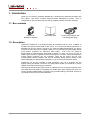
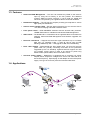
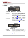
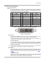
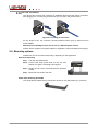
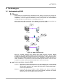
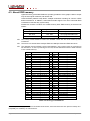
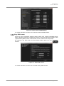
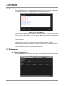
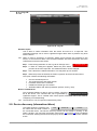
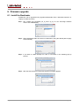
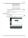
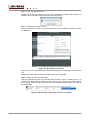
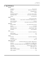
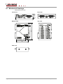
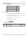
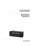
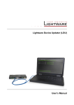
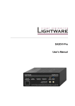
DA2DVI-DL User’s Manual DA2DVI-DL User’s Manual SAFETY INSTRUCTIONS Class II apparatus construction. This equipment should be operated only from power source indicated on the product. To disconnect safely from power, remove the power cord from the rear of the equipment, or from the power source. The MAINS plug is used as the disconnect device, the disconnect device shall remain readily operable. There are no user-serviceable parts inside of the unit. Removal of the bottom cover will expose dangerous voltages. To avoid personal injury, do not remove the bottom cover. Do not operate the unit without the cover installed. The apparatus shall not be exposed to dripping or splashing and that no objects filled with liquids, such as vases, shall be placed on the apparatus. The apparatus must be safely connected to multimedia systems. Follow instructions described in this manual. WEEE ( W as te E l e c tr ic a l & E lec tr on ic Eq u ipm en t ) Correct Disposal of This Product This marking shown on the product or its literature, indicates that it should not be disposed with other household wastes at the end of its working life. To prevent possible harm to the environment or human health from uncontrolled waste disposal, please separate this from other types of wastes and recycle it responsibly to promote the sustainable reuse of material resources. Household users should contact either the retailer where they purchased this product, or their local government office, for details of where and how they can take this item for environmentally safe recycling. Business users should contact their supplier and check the terms and conditions of the purchase contract. This product should not be mixed with other commercial wastes for disposal. Section 1. Introduction Page 3 / 33 DECLARATION OF CONFORMITY We, Lightware Kft. 1071 Budapest Peterdy str. 15 HUNGARY as manufacturer declare, that the product DA2DVI-DL ( Computer Monitor Extender ) in accordance with the EMC Directive 2004/108/EC and the Low Voltage Directive 2006/95/EEC are in conformity with the following standards: EMI/EMC .................... EN 55103-1 E3, EN 55103-2 Safety .......................................... EN 60065 Class I Date: 01 October 2013 Name: Gergely Vida ( Managing Director ) Signed: Page 4 / 33 Section 1. Introduction DA2DVI-DL User’s Manual Table of contents 1. INTRODUCTION ...................................................................................................................... 6 1.1. 1.2. 1.3. 1.4. 2. CONTROLS AND CONNECTIONS......................................................................................... 8 2.1. 2.2. 2.3. 2.4. 3. 3.2. 5.5. 5.6. 5.7. GENERAL PROBLEMS......................................................................................................... 30 PICTURE IS NOT DISPLAYED OR DISTORTED ........................................................................ 30 SPECIFICATIONS ................................................................................................................. 31 8.1. 9. INSTALL THE BOOTLOADER ................................................................................................ 26 UPGRADE PROCESS .......................................................................................................... 27 TROUBLESHOOTING ........................................................................................................... 30 7.1. 7.2. 8. INSTALLING THE LIGHTWARE DEVICE CONTROLLER SOFTWARE ........................................... 16 ESTABLISHING THE CONNECTION ....................................................................................... 18 I/O PARAMETERS MENU .................................................................................................... 19 EDID MENU ...................................................................................................................... 20 Sources and Destinations ....................................................................................... 20 EDID operations ...................................................................................................... 21 EDID summary window........................................................................................... 22 Advanced EDID Editor ............................................................................................ 22 Easy EDID creator .................................................................................................. 23 TERMINAL MENU ............................................................................................................... 24 STATUS MENU................................................................................................................... 24 Device information tab ............................................................................................ 24 Log tab .................................................................................................................... 25 DEVICE DISCOVERY (INFORMATION RIBBON) ....................................................................... 25 FIRMWARE UPGRADE......................................................................................................... 26 6.1. 6.2. 7. POWERING ON .................................................................................................................. 13 STATUS INDICATOR LEDS ................................................................................................. 13 ABOUT EDID MEMORY ...................................................................................................... 14 SWITCHING THE EDID ....................................................................................................... 15 LEARNING THE EDID......................................................................................................... 15 SOFTWARE CONTROL – USING LIGHTWARE DEVICE CONTROLLER ......................... 16 5.1. 5.2. 5.3. 5.4. 6. UNDERSTANDING EDID..................................................................................................... 11 Basics...................................................................................................................... 11 Common problems related to EDID ........................................................................ 11 ADVANCED EDID MANAGEMENT ........................................................................................ 12 OPERATION .......................................................................................................................... 13 4.1. 4.2. 4.3. 4.4. 4.5. 5. FRONT VIEW ....................................................................................................................... 8 REAR VIEW ......................................................................................................................... 8 ELECTRICAL CONNECTIONS ................................................................................................. 9 DVI connectors ......................................................................................................... 9 DC +5V connection ................................................................................................. 10 MOUNTING OPTIONS .......................................................................................................... 10 TECHNOLOGIES................................................................................................................... 11 3.1. 4. BOX CONTENTS................................................................................................................... 6 DESCRIPTION...................................................................................................................... 6 FEATURES .......................................................................................................................... 7 APPLICATIONS .................................................................................................................... 7 MECHANICAL DRAWINGS.................................................................................................... 32 VERSION APPLICABILITY ................................................................................................... 33 10. WARRANTY .......................................................................................................................... 33 11. DOCUMENT REVISION HISTORY ....................................................................................... 33 Section 1. Introduction Page 5 / 33 1. Introduction Thank you for choosing Lightware DA2DVI-DL, a dual-link DVI distribution amplifier with two outputs. This device includes Advanced EDID Management function, which is configurable on the front panel and via USB by Lightware Device Controller software. 1.1. Box contents DA2DVI-DL distribution amplifier Quick start guide +5V DC power adaptor with interchangeable plugs 1.2. Description Lightware's DA2DVI-DL is an EDID emulator and repeater that can store 79 EDIDs. It emulates and keeps a fixed EDID for the source, so it can provide stable signal which is distributed to the two outputs. Thanks to our Advanced EDID Management, the device can trick the DVI source (PC computer, laptop, etc.) by emulating any DVI/HDMI display (LCD monitor, projector) for continuous video output – even if the AV system is disconnected or powered down. With EDID emulation, the user can set up any DVI or HDMI output resolution, regardless of the used projector or monitor. This ensures that the overall system resolution can be controlled. There are 50 factory and 29 user programmable presets available, and the last attached display device's EDID is also stored separately on address #00, to be able to copy it to the input (repeater mode). DA2DVI-DL can be rack mounted or used standalone. The unit is equipped with the highest grade gold plated connectors and gold plated printed circuit boards to ensure reliable connections and long-term operation. With the Easy EDID Creator (that is built in Lightware Device Controller Software) users can create their own EDID by completing four simple steps. More experienced users can use the Advanced EDID Editor to manage every possible setting in the EDID, which they can upload to the memory of the DA2DVI-DL. Page 6 / 33 Section 1. Introduction DA2DVI-DL User’s Manual 1.3. Features Advanced EDID Management – The user can emulate any EDID on the device's input by using the 50 factory or 29 user presets. The attached monitor's EDID on DVI-DL OUTPUT 1 can be read out, edited and stored as user presets by the Lightware Device Controller Software. Distribution Amplifier – The unit has two outputs providing pre-emphasis to ensure high quality DVI distribution. Various status indicator LEDs – See the status of the device in one second: Source +5V, Monitor hotplug and EDID emulation status. Front panel control – EDID ADDRESS selection with two decimal rotary switches, LEARN EDID button is available for Advanced EDID Management. USB control – The DA2DVI-DL is controllable via the Lightware Device Controller PC software. Advanced EDID Management and firmware upgrades are available. Dual-Link resolutions – Supports all Dual-Link signal resolutions up to 9.9 Gbit/s data rate, e.g. WUXGA (1.920 × 1.200) @ 120 Hz with CVT-RB blanking, WQXGA (2.560 × 1.600) @ 60 Hz with CVT-RB blanking. Fiber cable support – Self-powered DVI fiber cables using +5V from DVI sources (VGA cards, etc.) usually consuming more than 50 mA (maximum suggested by DVI 1.0 standard). Lightware devices support +5V 500 mA constant current output on both of its outputs to power long distance fiber optical cables, like our DVI-OPT-TX110. Universal power supply – DA2DVI-DL is equipped with a universal +5V power adaptor, which accepts AC voltages from 100 to 240 Volts with 50 or 60 Hz line frequency. Special plug of wall adaptor ensures safe power supply. This type of connector prevents unwanted extractions. 1.4. Applications Section 1. Introduction Page 7 / 33 2. Controls and connections 2.1. Front view Learn button DC input 1 2 Status indicator LEDs 4 Rotary switches 3 5 DVI-DL input 1 Learn button Stores the EDID of the display device attached to DVI-DL OUTPUT 1 in the selected memory address between #51..#79. For more information see section 4.5 on page 15. 2 Status indicator LEDs Display EDID information during operation and the installed firmware version during system boot up. For more information see section 4.2 on page 13. 3 DC input Connect the output of the supplied +5V power adaptor or use Lightware’s rack mountable power supply unit. See more information in section 2.3.2 on page 10. 4 Rotary switches The rotary switches select one of the EDID memory addresses. See more information in section 4.4 on page 15. 5 DVI-DL input Connect one single or dual-link DVI cable (only digital pins are connected internally) between the DVI source and DA2DVI-DL. See more information in section 2.3.1 on page 9. 2.2. Rear view 1 USB control DVI-DL outputs Page 8 / 33 2 1 USB control Advanced EDID management and firmware upgrades are available via the USB interface. 2 DVI-DL outputs Connect single or dual-link DVI cables (only digital pins are connected internally) between DA2DVI-DL and the display devices. The output connectors are able to supply 500 mA current on pin 14 to power fiber optical DVI extenders like Lightware’s DVI-OPT-TX110. See more information in section 2.3.1 on page 9. Section 2. Controls and connections DA2DVI-DL User’s Manual 2.3. Electrical connections DVI connectors DA2DVI-DL provides 29 pole „digital only” DVI-I Dual-Link connectors (only digital pins are internally connected). This way, users can plug in any DVI connector, but keep in mind that analog signals (such as VGA or RGBHV) are not processed. Always use high quality DVI cable for connecting sources and displays. Pin Signal Pin Signal Pin Signal 1 TMDS Data2- 9 TMDS Data1- 17 TMDS Data0- 2 TMDS Data2+ 10 TMDS Data1+ 18 TMDS Data0+ 3 TMDS Data2/4 Shield 11 TMDS Data1/3 Shield 19 4 TMDS Data4- 12 TMDS Data3- 20 TMDS Data0/8 Shield TMDS Data5- 5 TMDS Data4+ 13 TMDS Data3+ 21 TMDS Data5+ 6 DDC Clock 14 +5V Power 22 TMDS Clock Shield 7 DDC Data 15 GND (for +5V) 23 TMDS Clock+ 8 nc 16 Hot Plug Detect 24 TMDS Clock- C1 nc C2 nc C3 nc C4 nc C5 GND Table 2-1. DVI-I digital only connector dual link pin assignments 1 2 3 4 5 6 7 8 C1 C2 9 10 11 12 13 14 15 16 17 18 19 20 21 22 23 24 C3 C4 C5 Figure 2-1. DVI-I connector DVI-DL outputs Monitor hotplug is detected on the DVI-DL OUTPUT 1 (HPD LED lights green). After a hotplug event, the DA2DVI-DL tries to read the EDID of the connected device. No output reclocking is provided. If a long DVI cable is connected then equalization and reclocking may be necessary at the receiver end of the cable. Fiber Cable powering As a special feature, the device is able to supply 500 mA current on DDC +5V output (pin 14 on the output connectors) to power fiber optical DVI transmitters. Standard DVI outputs or VGA cards supply only 55 mA current on +5V output, thus unable to power directly a fiber optical cable. Info: The device does not check if the connected sink (monitor, projector or other equipment) supports hotplug or EDID signals but outputs the input signal directly. DVI-DL inputs The input has Dual-Link disable option, which ensures Single-Link compatibility. Devices supporting Dual-Link output can confuse Single-Link inputs; disabling the Dual-Link TMDS channel distribution solves this problem. For more information see section 5.4 on page 19. Cable length at inputs DA2DVI-DL has no built-in cable equalization circuit. Be sure to use no longer than 5m cable. If there is more distance needs to be covered, please use one of our cable extender solutions, for example the Lightware DVIDL-Extender. Section 2. Controls and connections Page 9 / 33 DC +5V connection The device has a locking DC connector to establish robust and safe power connection. After plugging it in, turn the plug clockwise as you can see in the picture below. Figure 2-2. Locking DC connector Do not forget to turn the connector counterclockwise before trying to disconnect the power adaptor. Warranty void if damage occurs due to use of a different power source. Always use the supplied +5V power adaptor or Lightware’s rack mountable power supply. 2.4. Mounting options DA2DVI-DL can be mounted several ways, depending on the application. Rack shelf mounting Step 1. Turn the unit upside down. Step 2. Put the rack shelf upside down on the unit, and position it to get the mounting holes aligned. Step 3. Fasten the unit on the rack shelf with the provided screws. Step 4. Mount the rack shelf in the rack. Under desk mounting kit double The UD-kit double makes easy to mount two devices on any flat surface (e.g. furniture). Page 10 / 33 Section 2. Controls and connections DA2DVI-DL User’s Manual 3. Technologies 3.1. Understanding EDID Basics EDID stands for Extended Display Identification Data. Simply put, EDID is the passport of display devices (monitors, TV sets, projectors). It contains information about the display’s capabilities, such as supported resolutions, refresh rates (these are called Detailed Timings), the type and manufacturer of the display device, etc. After connecting a DVI source to a DVI display, the source reads out the EDID to determine the resolution and refresh rate of the image to be transmitted. Figure 3-1. EDID communication Most DVI computer displays have 128-byte long EDID structure. However, Digital Televisions and HDMI capable displays may have another 128 bytes, which is called E-EDID and defined by CEA (Consumer Electronics Association). This extension contains information about additional Detailed Timings, audio capabilities, speaker allocation and HDMI capabilities. It is important to know, that all HDMI capable devices must have CEA extension, but not all devices are HDMI capable which have the extension. Common problems related to EDID Problem: My system consists of the following: a PC, then a DA2DVI-DL, then an WQHD (2560x1440) LCD monitor and a Full-HD (1920x1080) projector. I would like to see the same image on the monitor and the projector. What EDID should I chose on the DA2DVI-DL?” Solution: Section 3. Technologies If you want to see the image on both displays, you need to select the resolution of the smaller display (in this case Full-HD), otherwise the smaller display may not show the higher resolution image. Page 11 / 33 Problem: „I turned the rotary switch on the DA2DVI-DL to have a different resolution but nothing happens.” Solution: Some graphics cards and video sources read out the EDID only after powerup and later they don’t sense that EDID has been changed. You need to restart your source to make it read out the EDID again. Problem: „I have a DA2DVI-DL and I’m using a Lightware factory preset EDID. I would like to be able to choose from different resolutions, but my source allows only one resolution.” Solution: Most Lightware factory preset EDIDs allow only one resolution, forcing the sources to output only that particular signal. You need to select the Universal EDID (address #49). It supports all common VESA resolutions. Additionally it also features audio support. 3.2. Advanced EDID management Each DVI/HDMI sink (e.g. monitors, projectors, plasma displays, and switcher inputs) must support the EDID data structure. Source BIOS and operating systems are likely to query the sink using DDC2B protocol to determine what pixel formats and interface are supported. DVI/HDMI standard makes use of EDID data structure for the identification of the monitor type and capabilities. Most DVI/HDMI sources (VGA cards, set top boxes, etc) will output DVI/HDMI signal after accepting the connected sink’s EDID information. In case of EDID readout failure or missing EDID the source will not output DVI video signal. DA2DVI-DL provides Lightware’s Advanced EDID Management function which helps system integration. The DA2DVI-DL stores and emulates 78 EDID data plus the EDID of the last attached monitor connected to the output. First 50 EDID are factory presets, while memories #51..#79 are user programmable. The device stores the EDIDs in non-volatile memory. This way the EDID from the monitor is available when the monitor is unplugged, or switched off. The EDID emulated on the input can be copied from the DA2DVI-DL's memory (static EDID emulation) or from the attached monitor (dynamic EDID emulation). For example, the DA2DVI-DL can be set up to emulate the device, which is connected to DVI-DL OUTPUT 1, and the EDID automatically changes, if the monitor is replaced with another display device (as long as it has a valid EDID). Info: The user is not required to disconnect the DVI cable to change an EDID as opposed to other manufacturer’s products. EDID can be changed even if source is connected to the DVI-DL INPUT and powered ON. Info: When the emulated EDID has been changed, the device toggles the HOTPLUG signal for 2 seconds. Some sources do not observe this signal, so in this case the change is not recognized by the source. In such cases the source device must be restarted or powered OFF and ON again. Page 12 / 33 Section 3. Technologies DA2DVI-DL User’s Manual 4. Operation 4.1. Powering on When building an electronic system, make sure that all of the devices are powered down before connecting them. Powered on devices may have dangerous voltage levels that can damage sensitive electronic circuits. Step 1. After the system is complete, connect and fix the DC power cable to the unit and then to the power outlet. The unit is immediately powered ON. Step 2. After powered on, the unit performs a self-test and then the OUTPUT LOCK buttons starts blinking red. Startup process Step 1. After being powered on, the DA2DVI-DL displays its firmware version using the EDID STATUS LEDs. The following example shows this process for a firmware version of 1.2.1: Red blinks once → Short pause → Green blinks twice → Short pause → Red and Green blinks once. Step 2. After indicating the firmware version, the red or green EDID STATUS LED lights up depending on the selected EDID’s validity: Red – ‘N’: the selected EDID is invalid. Green – ‘Y’: the selected EDID is valid Step 3. If a display device is connected to DVI-DL OUTPUT 1, the DA2DVI-DL reads the EDID from the attached monitor’s EDID memory. If the read process is successful, the STATUS LED blinks green four times. If the read process is unsuccessful, the STATUS LED blinks red four times. Step 4. The normal function of the LEDs is in effect. Info: If none of the LEDs light up upon power-up, the unit is most likely damaged and further use is not advised. Please contact [email protected]. 4.2. Status indicator LEDs EDID status N (red) EDID status Y (green) HPD (green) SRC +5V (green) The LEDs display basic information about EDID and connected devices’ status: LED label LED is illuminated LED is blinking EDID STATUS N Selected EDID is invalid EDID learn failure EDID STATUS Y Selected EDID is valid EDID learn success HPD Hotplug detect: OUTPUT 1 is connected - SRC +5V Source connected:+5V present on INPUT - Table 4-1. Status indicator LEDs Info: LEDs display the installed Firmware version during startup as described in section 4.1. Section 4. Operation Page 13 / 33 4.3. About EDID memory Lightware factory preloaded EDIDs are specially provided to force graphic cards to output only the exact pixel resolution and refresh rate. Universal EDID (address 49#) allows multiple resolutions including all common VESA defined resolutions. In addition, it also features audio support. The use of universal EDID is advised for fast and easy system setup. DA2DVI-DL contains a 79 block non-volatile memory bank. EDID memory is structured as follows: Rotary switch state Memory bank number #01..#50 F01..F50 Factory Preset EDID list #51..#79 U01..U29 User programmable slots #00 D01 Last attached monitor’s EDID Info: The Factory Preset EDID list cannot be modified. These are the most commonly used resolutions. Info: The device can handle both 128 Byte EDID and 256 Byte extended EDID structures. Info: The attached monitor’s EDID is stored automatically, until a new monitor is connected to the OUTPUTs. In case of powering the unit off, the last attached monitor’s EDID remains in non-volatile memory. MEM Resolution MEM #00 #01 Copy from DVI OUTPUT 1 640 x 480 @ 60.0 Hz 640 x 480 @ 75.0 Hz 848 x 480 @ 60.0 Hz 800 x 600 @ 50.0 Hz 800 x 600 @ 60.30 Hz 800 x 600 @ 74.99 Hz 1024 x 768 @ 49.98 Hz 1024 x 768 @ 60.0 Hz 1024 x 768 @ 75.2 Hz 1152 x 864 @ 75.0 Hz 1280 x 768 @ 50.0 Hz 1280 x 768 @ 59.92 Hz 1280 x 768 @ 75.0 Hz 1360 x 768 @ 60.1 Hz 1364 x 768 @ 50.0 Hz 1364 x 768 @ 59.93 Hz 1364 x 768 @ 74.98 Hz 1280 x 1024 @ 50.0 Hz 1280 x 1024 @ 60.1 Hz 1280 x 1024 @ 75.1 Hz 1366 x 1024 @ 59.99 Hz 1400 x 1050 @ 49.99 Hz 1400 x 1050 @ 59.99 Hz 1400 x 1050 @ 75.0 Hz 1680 x 1050 @ 59.99 Hz #26 #27 #02 #03 #04 #05 #06 #07 #08 #09 #10 #11 #12 #13 #14 #15 #16 #17 #18 #19 #20 #21 #22 #23 #24 #25 #28 #29 #30 #31 #32 #33 #34 #35 #36 #37 #38 #39 #40 #41 #42 #43 #44 #45 #46 #47 #48 #49 #50 Resolution 1600 x 1200 @ 50.0 Hz 1600 x 1200 @ 60.0 Hz 1920 x 1200 @ 59.55 Hz 1920 x 1200 @ 50.0 Hz 1440 x 480i @ 60.3 Hz 1 640 x 480 @ 59.94 Hz 1 720 x 480 @ 59.92 Hz 1 1440 x 576i @ 50.6 Hz 1 720 x 576 @ 50.0 Hz 1 1280 x 720 @ 50.0 Hz 1 1280 x 720 @ 60.0 Hz 1 1920 x 1080i @ 50.3 Hz 1 1920 x 1080i @ 50.0 Hz 1 1920 x 1080i @ 60.5 Hz 1 1920 x 1080 @ 24.0 Hz 1 1920 x 1080 @ 24.99 Hz 1 1920 x 1080 @ 30.0 Hz 1 1920 x 1080 @ 50.0 Hz 1 1920 x 1080 @ 49.99 Hz 1 1920 x 1080 @ 60.0 Hz 1 2048 x 1080 @ 49.99 Hz 2048 x 1080 @ 50.0 Hz 2048 x 1080 @ 59.99 Hz Universal EDID 2560 x 1600 @ 59.85 Hz Table 4-2. Factory preset EDID list 1 HDMI compliant factory presets. Various embedded audio formats, YCbCr422/YCbCr444 color spaces and deep color compatibility are enabled by the CEA extension. Page 14 / 33 Section 4. Operation DA2DVI-DL User’s Manual 4.4. Switching the EDID Info: Use a flat head screwdriver that fits into the actuator. Avoid the use of keys, coins, knives and other sharp objects because they might cause permanent damage to the rotary switches. Step 1. Use a screwdriver to change the EDID ADDRESS by the rotary switches on the front panel of the DA2DVI-DL. Figure 4-1. Location #17 is selected by the rotary switches Step 2. After either one of the rotary switches has been rotated, the unit waits approximately two seconds before the selected EDID becomes active. Step 3. Check the state of the device: EDID status Y illuminated (green): The selected EDID is valid EDID status N illuminated (red): The selected EDID memory is invalid (wrong address / empty user memory) The address #00 has a special function. If a monitor is connected to OUTPUT 1, then its EDID is copied to the DVI-DL INPUT connector. If no monitor is connected to the OUTPUT 1 then the EDID transmitted to the INPUT connector is the EDID of the last recognized monitor. Info: If an invalid EDID is selected, DA2DVI-DL does NOT give a HOT PLUG signal to the source connected to DVI-DL INPUT. Info: After every EDID change, DA2DVI-DL toggles the HOT PLUG signal for approximately 2 seconds. Some graphics cards or DVD players do not sense the HOT PLUG signal, and even if EDID has been changed, the set resolution is not affected. In this case the source device must be restarted, or powered OFF and ON again. 4.5. Learning the EDID Info: The factory preset EDIDs cannot be changed by the user. Only addresses from #51 to #79 are user programmable. Step 1. After connecting the sink device to DVI-DL OUTPUT 1, use a screwdriver to select a user programmable memory address. EDIDs are stored in multiple programmable non-volatile memories. If the red EDID STATUS LED is illuminated, then the memory slot is empty and ready to be programmed. If the green is illuminated, the memory was already used before, but still available for reprogramming. Step 2. Push the LEARN EDID button on the front panel of the DA2DVI-DL and hold it down for approximately 2 seconds. The green EDID STATUS LED blinks four times if the EDID has been learnt successfully; the red LED blinks four times in the case of unsuccessful attempt. Step 3. The normal function of the LEDs is in effect. Section 4. Operation Page 15 / 33 5. Software control – Using Lightware Device Controller The device can be controlled by a computer using Lightware Device Controller. The software can be installed to a Windows PC or MAC OS X. The application and the User’s manual can be downloaded from www.lightware.eu. After the installation the Windows and the Mac application has the same look and functionality. 5.1. Installing the Lightware Device Controller Software Info: LDC can be installed to Max OS X operating system – with the same look and functionality; see the User’s manual of LDC. Step 1. Run Install_LDC_v1.0.0b1.exe If the User Account Control drops a popup message click Yes. Step 2. A welcome window opens. Click Next. Step 3. Select the type of the installation. Here can be chosen the normal and the snapshot install. Select the optional components then click Next. (Using the Normal install as the default value is highly recommended.) Page 16 / 33 Section 5. Software control – Using Lightware Device Controller DA2DVI-DL User’s Manual Step 4. Select the destination folder and click Next. (Using the default path is highly recommended.) Step 5. Select the Start Menu Folder and click Next. (Using the default folder is highly recommended. If the Start menu entries was not checked in the Step 2. this window will be skipped.) Step 6. Verify the settings and if they are correct click Install. (If not, click Back and change the setting.) Step 7. After the installation of the last component the Next button is activated. Click on it. Step 8. If the installation is complete, click Finish. (Uncheck the box if the running of the LDC will be delayed.) Section 5. Software control – Using Lightware Device Controller Page 17 / 33 5.2. LDC Upgrade Step 1. Start the application. The Device Discovery window appears automatically and the program checks the available updates on the Lightware website and opens the update window if the LDC found updates. The current and the update version number can be seen in the top of the window and they are shown in this window even with the snapshot install. Step 2. Set the desired update setting in the option section. a) If you do not want to check the update automatically, uncheck the circle, which contains the green tick. b) If the postponing is the desired choice for the updating, the reminder can be set for different duration with the drop-down list. c) If the proxy settings traverse the update process, set the proper values then click the OK button. Step 3. Click the Download update button to start the upgrading. User can check updates manually by clicking the Check now button. Page 18 / 33 Section 5. Software control – Using Lightware Device Controller DA2DVI-DL User’s Manual 5.3. Establishing the connection Step 1. Connect the device to the computer via an USB mini B cable. Step 2. Start the application. Step 3. The Device Discovery window appears automatically, DA2DVI-DL is going to appear in a few seconds in section USB devices. The device type and the serial number are displayed automatically. Figure 5-1. USB connection Step 4. Select the device, and click on the Connect button. 5.4. I/O Parameters menu This menu displays the current state of the device. The input port of the device is on the right top, the output ports are on the right bottom side. Input port is displayed as default. Figure 5-2. DA2DVI-DL I/O Parameters menu Section 5. Software control – Using Lightware Device Controller Page 19 / 33 Press the button of the input/output port button to see the port settings. Figure 5-3. Output port properties Output pre-emphasis and Dual-Link disable options can be selectable by the buttons. Info: Output pre-emphasis and Dual-Link disable options are not available in hardware version SCH 1.0 - PCB1.0. 5.5. EDID menu Advanced EDID Management can be accessed by clicking on the EDID menu. This view is divided in two panels. Left panel contains the Source EDIDs, right one contains Destination places where the EDIDs can be emulated. The list can be scrolled by mouse wheel or by grabbing and moving up and down. Info: When the user enters the menu for the first time, the software starts to download the whole EDID list from the device. It may take a few seconds. Sources and Destinations After the list is downloaded, current status is shown. The EDID memory consists of four parts: Factory EDID list shows the factory preprogrammed EDID information on the F01..F50 memory locations. These locations can be reached by selecting 01#..50# on the rotary switches. User memory shows the user programmable, custom EDID information on the U01..U29 memory locations. These locations can be reached by selecting 51#..79# on the rotary switches. Both memory locations and rotary switch addresses are visible in the Memory column. Dynamic EDID list contains the resolution, manufacturer and vendor name of the display device connected to the device's output. The last display device’s EDID is stored, so there is an EDID shown even if there is no display device attached to the output of DA2DVI-DL in that moment. Emulated EDID list shows the currently emulated EDID for the input. It contains the resolution, manufacturer and vendor name of the EDID reported to the source. The emulated EDID can only be selected by the rotary switches on the input, to keep consistency. Page 20 / 33 Section 5. Software control – Using Lightware Device Controller DA2DVI-DL User’s Manual Figure 5-4. EDID management menu The DVI source reads the EDID from the Emulated EDID memory for the corresponding port. The user can copy an EDID from any of the three EDID lists to the user memory locations. This is called EDID routing. There are two types of emulation: Static EDID emulation happens, when an EDID from the Factory or User EDID list is selected by the rotary switches. In this case, the Emulated EDID will remain the same until the user emulates another EDID. Dynamic EDID emulation can be enabled by selecting 00# on the rotary switches. The attached monitor’s EDID is routed to the input, if a new monitor is attached to the OUTPUT 1, the emulated EDID changes automatically. EDID operations Changing the emulated EDID To change the EDID ADDRESS use the rotary switches on the front panel of the device. Info: If dynamic emulation is established, the emulated EDID will be changed on the input every time a new monitor is connected to the OUTPUT 1. If the monitor is disconnected from the OUTPUT 1, the last EDID remains emulated for the source. This feature helps especially rental technicians or system integrators to keep the source continuously transmitting the signal, and adopt the system for new incoming display devices. Info: Power ON/OFF cycle will not affect the emulated EDID or other settings. Info: Front panel status change is reported back to LDC. Learning EDID from attached display device via software DA2DVI-DL is able to learn the EDID from a connected display device and store it in one of the user programmable memory locations. Step 1. Press the Dynamic button above left panel and select the desired EDID. Step 2. Press the User button above right panel and select a memory place. Step 3. Press the Transfer button to store the EDID in the User memory. Exporting an EDID Source EDID can be downloaded as a file (*.dat, *.bin, or *.edid) to the computer. Step 1. Select desired EDID from the Source panel (highlight with yellow cursor). Save Step 2. Press Save button to open Save as dialog and download the file. Section 5. Software control – Using Lightware Device Controller Page 21 / 33 Importing an EDID Previously saved EDID (*.bin, *.dat, or *.edid) can be uploaded to user memory: Step 1. Press User button above Source panel. Step 2. Select a memory slot from the Source panel. Upload Step 3. Press the Upload button below Source panel. Step 4. Browse the file in the opening window then press the Open button. Browsed EDID is imported into the selected User memory. Info: The imported EDID overwrites the selected memory place even if it is not empty. Deleting an EDID The EDID(s) from the User memory can be deleted as follows: Step 1. Press User button above Destination panel. Step 2. Select desired memory slot(s); more ports can be selected. Use Select All and Deselect All buttons according to the needs. The EDID(s) will be highlighted with yellow cursor. Step 3. Press Delete selected button to delete the EDID(s). Delete selected EDID summary window Select an EDID from Source panel and press the Info button to display EDID summary. Info Figure 5-5. EDID summary window Advanced EDID Editor This powerful tool is essential for AV professionals. The Advanced EDID Editor is integrated into the Device Controller Software, and makes possible to manage every setting in the EDID on an intuitive user interface. The editor can read and write all descriptors, which are defined in the standards, including the additional CEA extensions. Any EDID from the device’s memory or a saved EDID file can be loaded in the editor. The software resolves the raw EDID, and displays it as readable information to the user. All descriptors can be edited, and saved in an EDID file, or uploaded to the device’s memory. By clicking on the Edit button, the editor area opens in a new window. Page 22 / 33 Edit Section 5. Software control – Using Lightware Device Controller DA2DVI-DL User’s Manual Figure 5-6. Open Advanced EDID Editor For further information, see the user’s manual of Advanced EDID Editor. Easy EDID creator Since the above mentioned advanced editor needs more complex knowledge about EDID, Lightware introduced a wizard-like interface for fast and easy EDID creation. With Lightware Easy EDID Creator custom EDIDs can be created in four simple steps. By clicking on the EEC button, the Easy EDID Creator opens in a new window. EEC Figure 5-7. Easy EDID Creator For further information, see the User’s manual of Easy EDID Creator. Section 5. Software control – Using Lightware Device Controller Page 23 / 33 5.6. Terminal menu The general purpose of this serial terminal is intended mainly for testing and debugging. Press the Terminal button in the right bottom corner to open the window. Figure 5-8. Terminal Window Commands are automatically surrounded by framing brackets as a default setting. Every sent command is red-colored and gets a ‘>’ prefix. Received responses are blue-colored and starts with ‘<’. Commands can be sent by pressing enter, or the Send button. The timecode in every row shows the exact time when the command was sent or the response received. If the Command framing checkbox is unchecked, you can send multiple commands together, however in this case you have to type in the framing brackets manually. If the Autoscroll checkbox is checked, the window is scrolled down automatically when a new row is added. The window can be emptied by pressing the Clear button. 5.7. Status menu Device information tab Basic information about the device, such as type, serial number, installed cards’ firmware and hardware revisions are displayed on this tab. Figure 5-9. Device information menu Page 24 / 33 Section 5. Software control – Using Lightware Device Controller DA2DVI-DL User’s Manual Log tab Figure 5-10. Log tab Generate report LDC is able to collect information from the device and save it to a report file. This information package can be sent to Lightware support team when a problem may arise with the device. Info: When a report is necessary to generate, always let the devices be connected to the device, do not disconnect them. The Controller Software will collect information about the USB devices and about their status. Step 1. Press the big red button on the Log tab in Settings menu. Generate report Step 2. A “Save as” dialog box appears. Select the place where you want to save the report file. The default file name can be changed. Step 3. LDC collects the needed information. This may take up to 5 minutes. Step 4. When the process is finished, the folder is opened, where the file was saved. The report contains the following information: Current command protocol The equipment type and serial number Firmware version of the controller Installed I/O board type and version All EDID headers and status (emulated, dynamic, factory, user) Browse command file The Controller Software is able to send a custom command Generate report from file file to the device. The command file can be generated by Lightware support. This is needed when some special commands has to be used for configuring or troubleshooting. Info: This function is only for special troubleshooting cases. 5.8. Device discovery (information ribbon) This label shows the interface type, USB DA2DVI-DL 1245678 the name and the serial number of the connected device. The Device discovery window can be started by clicking on this ribbon. Clicking “Yes” will open the window. See section 5.2 on page 18 how to establish the connection. Clicking No will close the pop up window and current connection remains active. Section 5. Software control – Using Lightware Device Controller Page 25 / 33 6. Firmware upgrade 6.1. Install the Bootloader DA2DVI-DL can be upgraded using Lightware Bootloader from a Windows based PC or Laptop via USB connection. Step 1. Run Installer_LW_bootloader_vX_X_X.exe (X_X_X is the three-digit software version of the Bootloader). Step 2. Select destination folder and click on Install button (using the default path is highly recommended). Step 3. If you want to create desktop icon click on Yes button in the following pop-up window. Step 4. After the files have been copied the following message appears: Page 26 / 33 Section 6. Firmware upgrade DA2DVI-DL User’s Manual Step 5. To finish the installation process, click on the Close button. Step 6. To run Lightware Bootloader, find the shortcut icon in Start menu Programs Lightware LW_bootloader_vX_X_X or on the desktop and double click on it. Uninstalling To uninstall the Bootloader software double click on Start menu Programs Lightware Uninstall_LW_bootloader_vX_X_X. 6.2. Upgrade process Step 1. Run the application from Start Menu Programs Lightware LW_bootloader_vX_X_X! Step 2. Click ‘FIND’ Button! If the bootloader finds one or more Lightware devices, their IP addresses, types and serial numbers are listed in the tree view window. Figure 6-1. Bootloader searches for devices Section 6. Firmware upgrade Page 27 / 33 Step 3. Select the desired device! Double click on the type name, then click ‘YES’ to establish connection with the device. It will take 10-15 seconds to get all information from the device. Step 4. Review the firmware versions! After the connection is made, the device properties, and the installed controller modules are displayed. Figure 6-2. Bootloader main screen Select one or more controllers that need firmware upgrade by clicking the checkbox next to it. DA2DVI-DL is the main processor’s firmware that can be upgraded. Step 5. Browse for the new firmware(s)! Click the corresponding cell in the ‘Browse New Firmware’ column. A dialog pops up, to confirm if you really want to modify the path. Now you can browse for the new firmware file to upload. After opening the new file, the new firmware field will contain the name of the firmware file. Figure 6-3. Bootloader – Select the controller to upgrade Page 28 / 33 Section 6. Firmware upgrade DA2DVI-DL User’s Manual Step 6. Upgrade firmware(s) Click ‘UPGRADE SELECTED FIRMWARES’ button. A confirmation message appears. After clicking the ‘YES’ button the selected controller is being reprogrammed, with the firmware you selected. If you select a file that doesn’t fit for the selected controller, you will get an information message about which file is wrong. If you selected the controller to upgrade, but you had not selected a file for it, then you will also get an information message about which file is missing. Quick Bootload mode can be switched on or off any time. It makes the bootloader software faster by only checking the checksum of the controller. No data verification is done after writing if the checksum was correct. Info: The reprogramming can take between 3-8 minutes per controller. A progress bar will show the current state of the reprogramming. With some controller type an erasing process will take place first, and then the programming is done, so the progress bar runs up twice. When the reprogramming is finished, a ‘Done!’ message will appear in the bottom left corner. The application closes the connection, and the device restarts. Step 7. Done! If the upgrade was successful, the following window pops up: Figure 6-4. Upgrade successful Now you can close the application, or you can select another device to upgrade. After closing the Bootloader application, switch the upgraded devices off and then on. Now it is ready to be used with the new firmware! Section 6. Firmware upgrade Page 29 / 33 7. Troubleshooting 7.1. General problems Check the device Check whether the DA2DVI-DL is properly powered and one of the EDID status LEDs is illuminated. Try performing a reset by unplugging and reconnecting the power adaptor. 7.2. Picture is not displayed or distorted Check the cables Due to the high data rates, the cables must fit very well. DVI connectors have to be locked with screws, no tensions or breaches are allowed. If your source or display as more connectors then make sure that the proper interface is selected. Be sure to use Dual-Link cable in case of Dual-Link data rates. To ensure compatibility Dual-Link channels can be switched off. Although the device is equipped with DVI-I connectors, analog signals are not supported. You cannot use VGA cables with DVI-VGA adapter plugs. Check EDID related problems Maybe your display device is not capable of receiving the sent video format. Try emulating your display device’s EDID to the source by selecting 00# on the front panel rotary switches. If you get a picture now, you have an EDID related issue, please read section 2 (Understanding EDID) for more details. Check the source Check whether your source is powered on and configured properly. The HDMI output can be turned off on most DVD players. If the source is a computer, then verify that the DVI output is selected and active. Try restarting your computer; if you get a picture during the booting process, you have to review the driver settings. Signal is encrypted The DA2DVI-DL does not provide HDCP functionality, because Dual-Link applications usually don’t need encrypted distribution. If the system design makes encrypted distribution necessary please have a look at our Single-Link or HDMI HDCP compliant devices, for example DA2DVI-HDCP-Pro. Page 30 / 33 Section 7. Troubleshooting DA2DVI-DL User’s Manual 8. Specifications General Compliance ....................................................................................... CE, UL, FCC EMI/EMC ........................................................................EN 55103-1, EN 55103-2 Safety ........................................................................................ EN 60065 Class II Warranty .................................................................................................... 3 years Operating temperature ................................................0 to +55°C (+32 to +122°F) Operating humidity ................................................... 10% to 90%, noncondensing Cooling ......................................................................................... Convection only Power Power supply .................................................................... external power adaptor Power adaptor ......................... input 100-240 V AC 50/60 Hz, Output 5V DC, 1 A Power consumption: .............................................................................1.4 W (typ) Power connector ......................................... Locking DC connector (2.35 mm pin) Enclosure Rack mountable ...................................................... Yes, with rack shelf (1U high) Material .................................................................................................1 mm steel Dimensions in mm ............................................................. 100.4W x 67.6D x 26H Dimensions in inch ............................................................ 3.95W x 2.66D x 1.02H Net weight ................................................................................... 235 g (0.496 lbs) Input Connector ....................................................................... 29-pole DVI-I digital only EDID emulation ................................................................................................ Yes Input cable equalization .....................................................................................No Output Connector ....................................................................... 29 pole DVI-I digital only Reclocking .........................................................................................................No +5V output current ..................................................................................... 500 mA Digital video signal Data rate ........................... all between 25 Mbps and 2.25 Gbps / TMDS channel Channels ........................................................ 1x TMDS Clock + 6x TMDS Colors Resolutions all between 640x480 and 1920x1200@60Hz or 2048x1080@60Hz Color depth ............................................................. maximum 36 bits, 12 bit/color Color format ............................................................................. RGB, YCbCr 4:4:4 HDTV resolutions .................................................................... 720p, 1080i, 1080p HDMI 1.3a audio compatible ........................................................................... Yes HDCP compliant ................................................................................................No Section 8. Specifications Page 31 / 33 8.1. Mechanical drawings Dimensions are in mm. Rear view 26 Front view 100.4 Top view 67.5 M3 thread 100.4 15.3 Bottom view 51.2 67.6 Side view Page 32 / 33 Section 8. Specifications DA2DVI-DL User’s Manual 9. Version applicability This User’s Manual applies to the following versions of the mentioned software, firmware and hardware: version Lightware Device Controller software 1.0.0b2 Lightware Bootloader software 3.3.0 DA2DVI-DL firmware 1.2.1 PCB 1.1 10. Warranty Lightware Visual Engineering warrants this product against defects in materials and workmanship for a period of three years from the date of purchase. The customer shall pay shipping charges when unit is returned for repair. Lightware will cover shipping charges for return shipments to customers. In case of defect please call your local representative, or Lightware at Lightware Visual Engineering H-1071 Budapest, Peterdy Street 15, HUNGARY E-mail: [email protected] 11. Document revision history Document Release Date Changes Editor Rev. 1.0 15-01-2015 Initial version Laszlo Zsedenyi Section 9. Version applicability Page 33 / 33