1
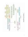
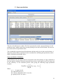
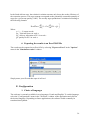
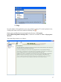
User Manual
Simulation tool
for sugarcane mill supply organization
Contacts:
Sandrine AUZOUX, data processing specialist, [email protected]
Caroline Lejars, agronomist, [email protected]
Pierre-Yves Le Gal, agronomist, [email protected]
Contents
Introduction ................................................................................................................................ 4
Computer modelling of mill supply areas .................................................................................. 5
I. Software tutorial................................................................................................................. 8
A. Mill supply area options................................................................................................. 8
1. To create a new mill supply area................................................................................ 8
2. To delete an existing mill supply area........................................................................ 9
3. To simulate a scenario for an existing mill supply area............................................. 9
B. Scenario options ............................................................................................................. 9
1. To create or modify a scenario................................................................................... 9
2. To duplicate a scenario............................................................................................. 10
3. To delete a scenario.................................................................................................. 10
4. To import a data file in an existing scenario ............................................................ 11
a) Mill sheet.............................................................................................................. 12
b) Cutting capacity sheet .......................................................................................... 13
c) Transloading capacity sheet ................................................................................. 13
d) Quality variable sheet........................................................................................... 13
e) Delivery allocation sheet...................................................................................... 13
C. To parameter a scenario ............................................................................................... 14
1. To parameter the mill supply area structure............................................................. 14
a) Mill characteristics ............................................................................................... 14
b) Production unit characteristics ............................................................................. 15
c) Intermediate operator characteristics ................................................................... 16
d) Routes................................................................................................................... 18
2. To parameter the season period................................................................................ 19
3. To parameter weekly capacities ............................................................................... 21
4. To parameter quality ................................................................................................ 23
5. To parameter delivery allocations ............................................................................ 25
a) Manual input ........................................................................................................ 26
b) Default value ........................................................................................................ 26
c) Uniform throughout the season ............................................................................ 27
d) Uniform throughout periods................................................................................. 27
D. Obtaining scenario simulation results .......................................................................... 29
1. Deliveries ................................................................................................................. 29
2. Capacities ................................................................................................................. 30
3. Quality...................................................................................................................... 32
4. Loading rates ............................................................................................................ 33
5. Sugar production ...................................................................................................... 35
6. Exporting the results to an Excel 2002 file .............................................................. 36
E. Configuration ............................................................................................................... 36
1. Choice of languages ................................................................................................. 36
2. Help .......................................................................................................................... 37
2
Table of illustrations
Picture 1: Pyramidal representation of the mill supply area structure……………...……..
Picture 2: Structure of the application ……………………...………...…………………...
Picture 3: Welcome screen………………………………………………………………...
Picture 4: Mill creation dialog box......................................................................................
Picture 5: Validation window to remove a mill supply area................................................
Picture 6: Scenario definition window……………………………………………….……
Picture 7: Scenario menu……………………………………………….............................
Picture 8: Scenario creation dialog box …………………………………………………..
Picture 9: Validation window to remove a mill………………………...............................
Picture 10: Open file dialog box………………………………………..............................
Picture 11: Data import window………………………………………………….…….…
Picture 12: Mill sheet in MAGI import format……………………………………............
Picture 13: Cutting capacity sheet……………………………………………………...….
Picture 14: Transloading capacity sheet…………………………………………………...
Picture 15: Quality indicator sheet………………………………………..……………….
Picture 16: Delivery allocation sheet………………………………...................................
Picture 17: Parameter menu.……………………………….……………….......................
Picture 18: Mill supply area structure definition window - Tab Mill……...……………...
Picture 19: Mill supply area structure definition window - Tab PU...…….………………
Picture 20; Options menu ………………………………………………………………....
Picture 22: Production unit creation dialog box ………………………….……………….
Picture 21: Mill supply area structure definition window - Tab IO……………………….
Picture 22: IO creation dialog box ………………………………………………………..
Picture 23: Mill supply area structure definition window - Tab Routes…………………..
Picture 24: Route creation dialog box………………………..............................................
Picture 25: Season period definition window ……………………………………….……
Picture 26: Dialog box to enter the weekly crushing capacity……………………….……
Picture 27: Tab PU - Cutting capacity ……………………………………………………
Picture 28: Tab IO - Transloading capacity………………………………………….……
Picture 29: Dialog box to enter the quality……………………………………………..…
Picture 30: Tab PU - Quality indicators…………………………………………………...
Picture 31: Dialog box to enter the delivery allocation……………………………….…...
Picture 32: Default value……………………………………………………………….….
Picture 33: Season period creation window………………………………………….…....
Picture 34: Error list preview ……………………………………………………………..
Picture 35: Simulation results option……………………………………………………...
Picture 36: Results window - Tab Deliveries……………………………………………...
Picture 37: Results window - Tab Capacities………..……………………………………
Picture 38: Results window - Tab Quality………………………………….......................
Picture 39: Results window - Tab Loading rate…………………………...........................
Picture 40: Results window - Tab Sugar production……..………….……………………
Picture 41: Export to Excel option ...……………...………………………........................
Picture 42: Language settings menu …………………..………………………………….
Figure 43: Help screen……...……………………………………………………………..
5
7
8
8
9
9
10
10
11
11
12
13
13
13
14
14
14
15
16
16
17
18
18
19
20
21
22
23
23
24
24
25
26
26
28
28
29
30
31
33
34
35
36
36
3
Introduction
This software was developed under a CIRAD research project carried out in collaboration
with INRA on supply organization in agro-industrial processing units.
It is based on a simulation model, focused on weekly management of cane flows from the
field to the mill. This model can be used to study impacts on sugar production, reorganization
of mill supply areas, modifications in delivery planning rules, as well as variations in the
supply chain capacity and quality.
Unplanned delivery or processing events can occur at various supply chain levels. By
simulating these unplanned events, the response capacity of a scenario can be tested with
respect to disruptions in the planning system.
Magi is a support tool for negotiations between growers and industrial millers as it specifies
possible ways of boosting total value while addressing all parties objectives and constraints.
4
Computer modelling of mill supply areas
Based on the weekly management of cane flows from a production unit to a mill, MAGI
provides a representation of the mill supply process throughout a sugar season.
The model provides a spatial representation of sugarcane flows to the mill. It’s based on
partitioning of the mill supply area at three levels, i.e. mill, intermediate
operators and production units, and also on the characterization of the routes of each
production unit to the mill.
A production unit (PU) is an elementary entity postulated or treated as being homogeneous
with respect to the delivered cane quality and rules applied to this cane by the mill for the
management of cane supply planning and piloting processes. For example, a section of a mill,
a group of farms, a homogeneous agroclimatic zone or a category of growers can define
production units. The partitioning choices depend on the chosen simulation objectives.
Intermediate operators (IO) are entities who incorporate the contributions of various
production units. Depending on their type, they are characterized by their transferring,
transporting or loading capacity.
The mill is the third representational level of the mill supply area structural organization. It
represents a request quantified by the cane milling capacity.
Routes represent pathways via which cane is hauled from the field to the mill. They are
characterized by the dimensioning features of the transloading and transport facilities.
A pyramidal structure was adopted, consisting of N entities through which cane flows transit.
Production units which deliver to intermediate operators are positioned at the base of the
pyramid. There can be several operator levels but each entity can only deliver to one higher
ranking entity. A simulation scenario is built only one mill. The user creates a library of
scenarios for each studied mill.
Mill
1
…
Intermediate operators
1
1
2
3
k
…
4
6
m
…
n
Production units
A scenario combines a set of assumptions concerning the supply organization in a mill supply
area. In Magi, it is based on only one mill, and a library of scenarios is compiled for each
studied mill. Magi can thus be used to test various supplying scenarios with the aim of
increasing sugar production at the mill gate, of taking full advantage of sugar content peaks
5
and minimizing losses to enhance the quality, while ensuring sufficient operating margins so
as to be ready for unplanned events (mill shutdowns, conveyor breakdowns, bad weather, etc.)
The first step involves creating a mill with one or more associated scenarios. Then the PU and
IO are characterised and the routes defined. Finally the delivered cane tonnages are
quantified. The model makes intermediate calculations on the mill (weekly working period,
crushing capacities, and season period) at the intermediate operator level concerning
incoming and outgoing cane flows, and at the production unit level concerning delivery
allocations.
The model can also be used to carry out simulations based on assumptions not concerning the
attribution of growers’ cane delivery rights. For example, the supply schedules (date and
tonnage) can be adjusted so as to optimally take advantage of the spatiotemporal variability in
sugar content of cane in a mill supply area. If maximum sugar content periods differ between
production units, the model can calculate the gains that could be achieved by changing the
delivery allocation. On the mill supply area scale, this involves determining homogeneous
cane ripeness zones, determining delivery schedules per zone so as to optimally exploit sugar
content patterns during the season period, and then assessing the potential advantages of this
new organization in terms of final sugar production gains. Lastly, it is possible to test whether
each new delivery allocation would involve redimensioning the harvesting, transporting,
storing and milling equipment.
At exit, Magi displays some tables of weekly deliveries for each intermediate operator and
production unit, some tables of weekly crushing mill capacities and weekly capacities related
to the three quality variables, some tables of weekly quality variable values for each
production unit, some tables of loading rates at all mill supply area levels and, obviously,
some tables of the weekly sugar production for each production unit and at the mill gate.
6
7
I. Software tutorial
A. Mill supply area options
1. To create a new mill supply area
Select "To create a new mill supply area", and then click "OK".
The following window is displayed. Enter a name of the mill supply area (usually the mill
name) and click OK".
8
2. To delete an existing mill supply area
Select "To delete an existing mill supply area" and confirm the deletion by clicking "OK"
in the following dialog box.
3. To simulate a scenario for an existing mill supply area
Select "To choose an existing mill supply area", then click "OK". The scenario definition
window is then displayed on the screen.
B. Scenario options
1. To create or modify a scenario
9
From the scenario definition window, select "Create" or "Modify" in the "Scenario"
menu.
The "Creation/modification of a scenario" window is displayed as follows:
The scenario name is an obligatory field. There must only be one. The scenario creation date
is the current date, but it can be modified. The Comment section gives details on the scenario.
It is not obligatory.
2. To duplicate a scenario
From the Scenario definition window, choose the scenario to be duplicated then select
"Duplicate" in the "Scenario" menu. All of the scenario parameters are duplicated and the
new scenario appears in the list. To delete a scenario
3. To delete a scenario
10
To delete an existing scenario, select the scenario to delete, select the "Delete" option in the
"Scenario" menu, and then confirm the deletion by clicking "OK".
4. To import a data file in an existing scenario
From the Scenario definition window, select "Import" in the "Scenario" menu.
Choose your data file and then click “Open”.
The "Imports" window is displayed as follows:
11
You can import all of the data or select only those which interest you. In the first two tables,
the "All" column enables the user to deal with a whole row. In the production units table, it is
also possible to deal with the columns by using the drop-down menu and one of the two
buttons located just below. The two buttons under the intermediate operators table also makes
it possible to deal with the column "transfer capacity". Click “OK” once your choice is made.
Data is imported from an Excel file in a preset format. The "FORMAT_En.xls" file is an
example of the MAGI importation file format. It can be found in the directory “C:\Program
Files\CIRAD\Magi2004”. This file is presented in the form of five sheets to fill in.
a) Mill sheet
12
The blue cells must be filled in.
b) Cutting capacity sheet
c) Transloading capacity sheet
d) Quality variable sheet
e) Delivery allocation sheet
13
C. To parameter a scenario
1. To parameter the mill supply area structure
Select "Supply area structure" in the "Parameter" menu in the "Scenario definition"
window.
a) Mill characteristics
The "Mills" tab gives all information concerning the mill.
14
The "Weekly average crushing capacity" is automatically computed with the "Weekly
working period", the "Hourly average crushing capacity" and the "Breakdown rate".
Green shading means that it is a computed field that cannot be manually modified.
To modify all other variables, select "Modify" in the "Options" menu.
b) Production unit characteristics
From the "Options" menu, it is possible to create, modify or remove a production unit after
having selected it in the list.
15
The following window appears:
Two possible creation options:
¾ Choose an existing production unit in another scenario
¾ Enter a new name
"Delivered tonnage" is a computed field which corresponds to the product of the area by the
yield. However, it can also be entered manually by the user.
c) Intermediate operator characteristics
16
As mentioned concerning production units, it is possible to create, modify, or delete an
intermediate operator from the "Options" menu.
The following window is displayed:
Two possible creation options:
¾ Choose an existing intermediate operator in an existing scenario
¾ Enter a name and then a type
To delete a type, it should first of all be selected in the drop-down menu then click
Similarly, to add one, just click
The
.
.
button on the right of the field validates the new type.
To register the current operator, click
at the bottom of the form.
17
d) Routes
As mentioned concerning production units, it is possible to create, modify, or delete a route
from the "Options" menu.
18
The following window is displayed:
To create a route, select a production unit in the drop-down menu (there can only be one route
per production unit). Then select an intermediate operator in the list of the operators (the first
list located on the left makes it possible to filter the intermediate operators by type). The
button is used to transfer the selected operator to the final list. This is process carried out for
each operator while strictly respecting the cane routing order. An operator can be deleted by
button while having previously selected it in the list of selected operators.
clicking the
2. To parameter the season period
Select "Definition of season period" in the "Parameter" menu in the "Scenario
definition" window.
19
The green "season length" and "season start" fields are calculated fields:
o The determination of the season period (in weeks) takes into account the total
tonnage of cane to be milled in the season, as estimated by growers, and the
average weekly milling capacity of the sugar refinery, estimated by the millers:
n
Dc ≅
∑ Tg
i =1
i
Cbhm
Where,
Tg: delivered tonnage of PU i
Cbhm: average weekly crushing capacity of the mill
n: number of PUs
o The season start is calculated from the length of the season period and the
season ending date.
Magi takes the first "Season period" field into account for the calculation of weekly flows.
Its default value corresponds to the computed value. However, it is possible to modify its
theoretical value to determine the exact time of the season period.
20
3. To parameter weekly capacities
Select "Weekly capacity" in the "Parameter" menu in the "Scenario definition" window.
In the "Mill" tab, the real weekly crushing capacity is calculated from the effective working
period (EWP).
The weekly working period of the mill is calculated in two times. Initially, we calculate a
working period without breakdowns according to the following general formula:
DFHP = 168h - maintenance time - planned breakdowns (closing for leave, etc.)
Then we calculate the effective working period after integration of an average breakdown
rate:
EWP = DFHP*(1 - breakdown rate)
For each week S, the weekly capacity of the mill is given by the following formula:
Weekly capacity = (168 - weekly maintenance time)* (1 – breakdown rate)* hourly
capacity
21
Note that the hourly capacity of the mill, when it varies, is calculated from an objective
extraction rate and quality of the cane that enters the mill, according to a yet to be determined
formula.
A default EWP value can be entered and can be allocated for each week of the season period
by clicking "OK". It is also possible to modify the EWP values individually for each week.
In the "PU" tab, as noted previously, a default cutting capacity value can be given per week
to the PU selected in the list. Moreover, a cutting capacity can be modified manually for a
given week.
22
In the "Intermediate operators" tab, the transfer capacity can be entered as explained
previously, i.e. by giving a default value or by a manual entry for a week given.
4. To parameter quality
Select "Quality" in the "Parameter" menu in the "Scenario definition" window.
23
The "Mill" tab concerns weekly sugar losses.
In "Reunion", "Losses 1" relate to the technical difference between the sample obtained at
the weigh scales and that obtained at the mill entrance. "Losses 2" represent the losses due
to the milling process. Total losses are calculated automatically as the sum of "Losses 1"
and "Losses 2" for one week by clicking "Calculation".
In "South Africa", there is no sampling done outside of the mill, so total losses can thus
be entered directly by entering a default value if the losses do not vary throughout the
season period, or by manually entering the values for each week.
24
The second "Production units" tab relates to the cane quality variables. The columns
"Ind1", "Ind2", "Ind3" correspond to weekly quality index values entered in the "Mill"
tab on the mill supply area structure definition level. The synthetic indicator corresponds
to the sugar content of the cane. A default value can be entered as a specific value for a
given week.
5. To parameter delivery allocations
Select "Delivery allocations" in the "Parameter" menu in the "Scenario definition"
window.
25
Magi proposes various delivery allocation calculation methods.
a) Manual input
Delivery allocations are entered individually for each week of the season. A check procedure
verifies that potential flows of the successive supply chain links are not exceeded.
b) Default value
A default value may also be entered and assigned to every week of the season.
26
c) Uniform throughout the season
The "Uniform throughout the season" option is selected to obtain an identical maximum
value for each week of the season.
DA = Total Tonnage PU / Season period
In this case, the two constraints "Delivery of total PU tonnage" and "Weekly mill capacity
not exceeded" are usually automatically taken into account.
d) Uniform throughout periods
Delivery periods during the season period in which delivery allocations are constant may also
be determined: The objective in this case is to ask each PU to deliver over a certain period,
according to a uniform weekly delivery allocation. For every PU, it is thus necessary to
determine the week of the beginning and end of delivery during the season period and to
calculate the weekly delivery allocations according to the following formula:
DA = PU Total Tonnage / PU Delivery period
PU Delivery Period (weeks) = week of end of delivery - week of beginning of delivery + 1
The "Total PU tonnage delivery" constraint is automatically taken into account. It is
essential that the calculated delivery allocation does not exceed the harvest capacity of the
production unit considered; otherwise an error message will be displayed. The user must then
extend this delivery period so as to remain under the harvest capacity.
The "Weekly mill capacity not exceeded" constraint must be checked once all the delivery
allocations are defined. For certain weeks, the sum of the PU deliveries may exceed this
capacity. When exiting a scenario, a listing of these weeks is thus displayed, with the
percentage exceeding the capacity calculated according to the formula:
n
Lij
i =1
Cbh j
Dh j = 100 × ∑
Where,
Dlij: deliveries of PU i in week j
Cbhj: weekly mill crushing capacity in week j
27
The period creation window is displayed as follows:
A beginning week and an ending week along with a tonnage rate (in %) are entered, and then
the period is entered by clicking . To delete a period, select it and then click . The number
of periods is calculated automatically. In this case, the delivery allocations will be the same
for each week of the period and proportional to the tonnage rate. Click
and
to scroll
down the list of created periods. Once the periods are defined, validate them by clicking
"OK". When certain constraints are not respected, a summary listing is displayed with an
explanation on each value exceeded per week. The following is an example:
28
D. Obtaining scenario simulation results
From the Scenario definition window, select Simulation results" in the "Scenario" menu.
The window includes five tabs:
1. Deliveries
29
The first table (PU->mill) represents the weekly cane deliveries of each production unit with
the total and the remainder to be delivered (total produced - total delivered) given in second
and last column. The last row represents the total for all units.
The second table (IO->mill) represents weekly cane flows of each intermediate operator with
the total given in the second column and the total for all intermediate operators given in the
last row.
2. Capacities
This tab represents the weekly mill capacities. The first table gives the crushing capacity; the
three following tables give the calculated weekly capacities relative to the three quality
variables, while the last gives the minima of the three previous values. The average is given in
the first column of each table. The crushing capacity is the same for the entire season period
(cf. capacity calculated on the mill screen).
30
The weekly capacities related to indices 1, 2 and 3 are calculated as follows:
First step: calculation of the weekly average quality values for the mill supply area for week j
and index K (Qukj):
m
Q ukj =
Q k ij × Lij
∑
i =1
m
Lij
∑
i =1
Where
k: 1, 2, 3
m: number of PUs
QUkj: weighted average of the quality of index k in week j
Qkij: value of the quality of index k for PU i in week j
Lij: delivery of PU i for week j
(Qkij were entered in the Quality module)
2nd step: calculation of the weekly capacities for week j and index k (Chekj) relative to the
three quality variables (and corresponding to the three lines of the table: Indices 1, 2 and 3)
C h e kj =
D fe j × (1 0 0 − T x p ) × C h o k
Q uk j
Where
Defj: the effective mill working period for week j
(value obtained from the "Weekly mill capacity" module)
Txp: breakdown rate in % (e.g. 3.6%) (value obtained from the “Mill” module)
Chok: hourly capacity for the quality variable of index k (t/h)
(value obtained from the “Mill” module)
Qukj: weighted averages for the quality variable of index k in week j
Third step: calculation of the weekly capacities minima for week j
(
)
(
Che j = min Che1 j , Che 2 j , Che3 j or Che j = min Chekj
k =1,2,3
)
31
3. Quality
The first four tables of this tab represent a weekly summary of the quality variables for each
production unit. The last column gives the weighted average for the season. The fifth table
represents the quality of the mill supply area.
Data from the Quality module are used for the qualities per PU and week, without further
calculation. The seasonal average per PU is calculated by weighting the weekly quality values
by their effective deliveries
n
n
j =1
j =1
Qi = ∑ Qij × Lij ÷ ∑ Lij
Where
Qi: weighted average quality of PU i for the season
Qij: quality of PU i in week j
Lij: deliveries of PU i in week j
32
The average weighted qualities per delivery for the mill supply area for week j (Quj) are
calculated by the following formula:
m
m
i =1
i =1
QU j = ∑ Qij × Lij ÷ ∑ Lij
Where
Qij: quality of PU i in week j
Lij: deliveries of PU i in week j
And the average weighted qualities per delivery are thus obtained for the mill supply area and
for the entire season (Qu).
m
n
m
n
QU = ∑ ∑ Qij × Lij ÷ ∑∑ Lij
i =1 j =1
i =1 j =1
Where
Qij: quality of PU i in week j
Lij: deliveries of PU i in week j
n: number of weeks
m: number of PUs
4. Loading rates
33
The first table represents the loading rates of the production units with the arithmetic average
for the season given in the second column. The second table represents the loading rates of the
intermediate operators. The third table represents the loading rate for the mill crushing
capacity, and the last table represents the loading rate for the quality.
The loading rates are calculated by dividing the quantities collected, transferred or milled by
the capacities calculated by type of operator. They are expressed in % (e.g. 95%):
τup
ij
=
ij
=
100 × Lij
Cri
Where
Lij: delivery of PU i in week j
Cri: harvest capacity of PU i
τoi
100 × Tij
Cti
Where
Tij: cane quantity transferred from IO p in week j
Cti: transfer capacity of IO p
τu
j
=
100 × Lu j
Cbh j
Where
Luj: cane quantity delivered to the mill in week j
Cbhj: mill crushing capacity in week j
τq
j
=
100 × Lu j
Che j
where
Luj: cane quantity delivered to the mill in week j
Chej: mill crushing capacity relative to the quality in week j
34
5. Sugar production
This tab is divided into two tables. The first represents the weekly sugar production of each
production unit, with the total for the season period given in the second column. The last row
gives the total for all production units.
The second table represents the mill production with the total given in the second column. A
drop-down menu makes it possible to select a method for calculating this production, which
differs for Reunion and South Africa.
Sugar production calculation:
In the Reunion case, the sugar content corresponds to the total quantity of sugar contained in
the cane and the technical variation represents losses due to cane quality as well as losses due
to the efficiency of the extraction process, thus giving the following sugar production
formula:
S
⎡m
⎤
Pr odTot = ∑ ⎢∑ Dlis × ( Qis − Pus )⎥
s=1 ⎣ i =1
⎦
Where
s = 1,..., S season weeks
Pus: total mill losses in s
Dlis: delivery allocation of PU i in week s
Qis: quality for PU i in week s
35
In the South African case, the technical variation concerns only losses due to the efficiency of
the extraction process. The sugar content corresponds to the potentially extractable quantity of
sugar for a given cane quality (%RV). The weekly sugar production is calculated according to
the following formula:
S
⎡
m
⎤
s =1
⎣
i =1
⎦
Pr odTot = ∑ ⎢(1 − Pus ) ∑ Dlis × Qis ⎥
Where
s = 1,..., S season weeks
Pus: Total mill losses in week s
Dlis: delivery allocation of PU i in week s
Qis: quality for PU i in week s
6. Exporting the results to an Excel 2002 file
The results can be exported to an Excel file by selecting "Export to Excel" in the "Options"
menu in the "Simulation results" window.
Simply name your file and then open it in Excel.
E. Configuration
1. Choice of languages
The software is currently available in two languages: French and English. To switch language,
select the "Configurations" menu in the "Welcome" window of the application and click on
the desired language. Depending on future applications, the software could eventually be
translated into Spanish.
36
2. Help
In each window of the application, users can get help by typing "F1" on the keyboard, or by
clicking the button or the menu with the following icon:
Help is also available directly in the application directory: C:\Program
Files\CIRAD\Magi2004\AideMagi.chm). A shortcut is available in: Start - all programs MAGI2.
The online Help window is as follows:
37
The Contents are listed on the left under headings and subheadings.
From the Index, users can view specific Help pages from keywords.
The "Search" function displays a list of pages containing the entered keywords.
A Preview of the selected page is displayed in the right pane.
38