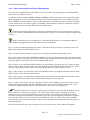
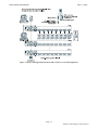
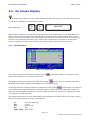
1
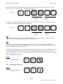
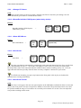
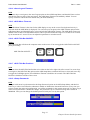
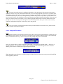
PRIMA-4 / PRIMA-8 / PRIMA-16
User Manual
Rev. 1.1
10/05/2007
Prima Switch User Manual
Rev 1.1 2007
Copyright and trademarks
Copyright © 2007 PROSUM. All rights reserved
All trademarks in this manual are the properties of their respective trademark owners.
Disclaimer
This User Guide fully explains the installation and use of PRIMA-4/PRIMA-8/PRIMA-16 KVM switches.
Since every precaution has been taken to prepare and write this manual, we assume no responsibility for
errors or omissions contained therein, nor any liability for damages resulting from the use of the information
in it. Specifications and functions may be changed without prior notice.
FCC Statement
This equipment has been tested and found to comply with the regulations for a Class B digital device,
pursuant to Part 15 of the FCC Rules. These limits are designed to provide reasonable protection against
harmful interference when the equipment is operated in a commercial environment. This equipment
generates, uses, and can radiate radio frequency energy and, if not installed and used in accordance with this
User Guide, may cause harmful interference to radio communications. Operation of this equipment in a
residential area is likely to cause harmful interference in which case, the user will be required to correct the
interference at his/her own expense.
CE Statement
This is a Class B product in a domestic environment this product may cause radio interference, in which case
the user may be required to take adequate measures.
Prima Switch User Manual
Rev 1.1 2007
Table of Contents
CHAPTER 1.
ADVANTAGES AND FEATURES................................................................................. 5
1.1
ADVANTAGES ................................................................................................................................... 5
1.2
GENERAL FEATURES ........................................................................................................................ 5
1.2.1 LED display for status monitoring............................................................................................... 5
1.2.2 Control features ........................................................................................................................... 6
1.2.3 Security ........................................................................................................................................ 6
1.2.4 Cascaded Application .................................................................................................................. 6
1.2.5 Hardware/Software Support ........................................................................................................ 6
1.2.6 Power interface............................................................................................................................ 6
1.2.7 Cabling requirements .................................................................................................................. 6
1.3
PACKAGE CONTENTS ....................................................................................................................... 6
1.4
FRONT PANEL ................................................................................................................................... 7
1.4.1 Buttons ......................................................................................................................................... 7
1.4.2 Numerical LED Displays and Indicators..................................................................................... 8
1.5
BACK PANEL .................................................................................................................................... 8
1.5.1 Power Jack................................................................................................................................... 9
1.5.2 Console Port ................................................................................................................................ 9
1.5.3 PC Ports....................................................................................................................................... 9
1.5.4 Daisy Chain Port ......................................................................................................................... 9
1.6
INSTALLATION................................................................................................................................ 10
1.6.1 Checklist before Installation...................................................................................................... 10
1.6.2 Mounting the Prima KVM switch .............................................................................................. 11
1.6.3 Daisy-chaining Several Prima KVM switches........................................................................... 12
CHAPTER 2.
PRIMA SWITCH OPERATION................................................................................... 14
2.1
FRONT-PANEL BUTTONS ................................................................................................................ 14
2.2
KEYBOARD HOTKEYS .................................................................................................................... 14
2.3
ON SCREEN DISPLAY...................................................................................................................... 16
2.3.1 OSD Main Menu ........................................................................................................................ 16
2.3.2 OSD Setup Menu........................................................................................................................ 17
2.4
OPERATE THE SWITCH.................................................................................................................... 17
2.4.1 <Select PC> .............................................................................................................................. 17
2.4.2 <Next lower channel>............................................................................................................... 18
2.4.3 <Next Higher Channel>............................................................................................................ 18
2.4.4 <Next Lower Bank> (when daisy-chained).............................................................................. 19
2.4.5 <Next Higher Bank> (when daisy-chained).............................................................................. 19
2.4.6 <Beep Sound On/Off>............................................................................................................... 19
2.4.7 <Load Default>......................................................................................................................... 19
2.4.8 <Load Default All> ................................................................................................................... 19
2.4.9 <Change PC Name> ................................................................................................................. 20
2.4.10
<Reset/Re-initialize KVM System (whole daisy-chain)> ...................................................... 20
2.4.11
<Show OSD Menu> .............................................................................................................. 20
2.4.12
<Auto Scan> ......................................................................................................................... 20
2.4.13
<Auto Scan Period> ............................................................................................................. 20
2.4.14
<Auto Logout Timeout>........................................................................................................ 21
2.4.15
<OSD Menu Timeout>.......................................................................................................... 21
2.4.16
<OSD Title Bar ON/OFF> ................................................................................................... 21
2.4.17
<OSD Title Bar Position> .................................................................................................... 21
2.4.18
<Setup Password> ................................................................................................................ 21
2.4.19
<Upgrade Firmware> .......................................................................................................... 22
APPENDIX A TECHNICAL SPECIFICATIONS ................................................................................... 23
Table of Contents
Prima Switch User Manual
Rev 1.1 2007
List of Figures
Figure 1: PRIMA-4 Front Panel ........................................................................................................................ 7
Figure 2: PRIMA-8 Front Panel ........................................................................................................................ 7
Figure 3: PRIMA-16 Front Pane ....................................................................................................................... 7
Figure 4: PRIMA-4 Back Panel ....................................................................................................................... 8
Figure 5: PRIMA-8 Back Panel ....................................................................................................................... 8
Figure 6: PRIMA-16 Back Panel...................................................................................................................... 9
Figure 7: PRIMA USB/PS2 PC Cable Assembly ........................................................................................... 10
Figure 8: Daisy Chain Cable ........................................................................................................................... 10
Figure 9: Upgrade Cable ................................................................................................................................. 11
Figure 10: Daisy Chain Terminator................................................................................................................. 11
Figure 11: Daisy-chaining multiple Prima KVM switches in a cascaded application .................................... 13
Figure 12: OSD Main Menu............................................................................................................................ 16
Figure 13: OSD Setup Menu ........................................................................................................................... 17
List of Tables
Table1 Summary for Hotkey Sequences 15
List of Figures &Tables
Prima Switch User Manual
Rev 1.1 2007
Chapter 1.
Advantages and Features
1.1
Advantages
PRIMA-4/PRIMA-8/PRIMA-16 is a 4/8/16-port cascadable rack mount USB PS/2 KVM switch with OSD
control. It provides both USB and PS/2 interface connectivity support on both PC side and console side. It
enables the administrator to access, control, boot, and reboot multiple USB and PS/2 computers using only
either USB or PS/2 keyboard, video, and mouse.
Centralized computer management from one keyboard, mouse and video
The PRIMA-4/PRIMA-8/PRIMA-16 KVM switch is a quality KVM switch designed for centralized
management of multiple computers/servers either in corporate, factory as well as in campus computing
environment. Its versatile connectivity support for both USB and PS/2 interface on console side and
computer side is especially convenient for a mixed environment with USB as well as PS/2 style computer.
Easy Operation by front-panel buttons, keyboard hot keys, and OSD menu controls
The PRIMA-4/ PRIMA-8/PRIMA-16 KVM switch can be easily operated using front-panel buttons,
keyboard hotkeys, as well as OSD Menu control. These available control features provide more convenient
and effective operation over your daily computer/server management routines and hence more productivity.
Flexible port capacity through multiple daisy-chained KVM switches
In addition to the choice over the different port capacities of the PRIMA-4/ PRIMA-8/PRIMA-16, users can
also take advantage of its cascadable feature to stack together up to 8 units of the KVM switches. For
example, with 8 units of the PRIMA-16 cascaded together, the total port management capacity could easily
be scaled up to 128 computers. You can scale the port capacity by daisy-chaining multiple units in different
combination according to your real needs.
Saving Time, Space and Money with more productivity
The KVM switches offer special advantages saving time, space and money plus a significant gain over
productivity of the server administrative staff. With our KVM switches, you eliminate the need for separate
sets of peripherals for each of your computers. The KVM users will also appreciate the neat space on desktop
or working bench that is free from multiple sets of keyboards, videos, and mice. On the other hand, the
server admin can save lots of time not to shift around separate sets of keyboard and mouse, just to keep up
with the server management routines. Hence, the KVM switch could be a tremendous help in facilitating a
better and more efficient work environment for server administration, and an indispensable productivity tool
for effective server/computer management.
1.2
General Features
1.2.1
LED display for status monitoring
Page 5
Chapter1 Advantages and Features
Prima Switch User Manual
Rev 1.1 2007
•
Numerical LED display for switch bank number
•
Front-panel port status LED's for easy port status monitoring
1.2.2
Control features
•
Front-panel buttons for direct channel selection
•
Auto Scan activated by keyboard hotkey
•
Keyboard hotkeys for quick operation commands
•
OSD Menu options for more convenient and intuitive control
•
Channel selection by front-panel buttons, keyboard hotkeys and OSD Menu control
1.2.3
Security
•
Auto Logout feature to lock up computer after a user-configurable timeout
•
Password security prevents unauthorized intrusion.
•
Provide 8-character password protection.
1.2.4
Cascaded Application
•
Auto-detect daisy-chain configuration without setting any dipswitch
•
Daisy-chaining up to 8 units for a scalable port capacity up to 128 computers using flexible
combination of different switch units
•
Numerical LED displays to indicate the switch bank number.
1.2.5
Hardware/Software Support
•
Support standard 5-key Microsoft, Logitech mice and compatibles
•
Support standard Microsoft, Logitech keyboards and compatibles
•
Support a wide range of software platforms: DOS, Windows 95 /98 /SE /NT/2000 /ME /XP/Server
2003/Vista, Unix, Linux and BSD
•
Hot plugging of PCs for maintenance without powering down the KVM switch or PC.
•
Support video graphic dimensions up to 2048 x 1536 pixels
1.2.6
Power interface
Powered by the external power adapter (9 VDC 1A) connected to the AC power outlet in addition to the
USB and PS/2 keyboard/mouse interface power
1.2.7
Cabling requirements
Special USB KVM Combo Cable, or PS/2 KVM Combo Cable, or the Combo-free USB PS/2 KVM Cable.
1.3
Package Contents
Page 6
Chapter1 Advantages and Features
Prima Switch User Manual
Rev 1.1 2007
The Packaging box of the PRIMA-4/PRIMA-8/PRIMA-16 KVM switch should contain the following items:
•
The PRIMA-4/PRIMA-8/PRIMA-16 KVM switch
•
Special USB KVM Combo Cable, or PS/2 KVM Combo Cable, or the Combo-free USB PS/2 KVM
Cable [Types of cable and number of cable sets will vary according to your option]
•
Daisy Chain Cable (M-HDB15-F) cable for cascaded application) x 1
•
(Daisy-Chain) Terminator x 1
•
Upgrade Cable (F-RS-232-F) x 1
•
Power adapter (AC to DC 9V 1A) x 1
•
Rack Mount Kit x 1
•
This User Guide x 1
•
A Quick Installation Guide x 1
1.4
Front Panel
Figure 1: PRIMA-4 Front Panel
Figure 2: PRIMA-8 Front Panel
Figure 3: PRIMA-16 Front Pane
1.4.1 Buttons
Press to switch to the corresponding port.
Page 7
Chapter1 Advantages and Features
Prima Switch User Manual
1.4.2
Rev 1.1 2007
Numerical LED Displays and Indicators
The Numerical LED display on the front-panel shows the switch bank number.
The Port Status is indicated by a set of two LED indicators:
•
The Live LED -- lit red when the computer is connected to the KVM switch and feeding power
through the PS/2 or USB interface.
•
The Selected LED – lit green when the computer is currently selected as the active channel
Thus, the red LED shows the current connected state of the specific port. The green LED indicator indicates
the currently active channel.
Note that a red-lit LED means only that the specific port is connected and being powered through its
PS/2 interface. It does not indicate whether that connected computer is in powered-on or powered-off state.
Note that a green-lit LED means only that the specific port is selected to be the active channel. It does
not indicate whether that connected computer is in powered-on or powered-off sate.
1.5
Back Panel
Figure 4: PRIMA-4 Back Panel
Figure 5: PRIMA-8 Back Panel
Page 8
Chapter1 Advantages and Features
Prima Switch User Manual
Rev 1.1 2007
Figure 6: PRIMA-16 Back Panel
1.5.1
Power Jack
The power jack should receive electricity from a 9VDC 1A power adapter cord. Its center pin is of a positive
polarity.
1.5.2
Console Port
The console port provides keyboard and mouse connectors for PS/2 as well USB interface, and a HDB 15
video connector for the monitor/LCD display.
1.5.3
PC Ports
The PC ports are HDB 15 connectors integrated with USB and PS/2 keyboard, mouse, and video. To connect
a PC port to one of your computer, you may either use USB KVM Combo Cable, or PS/2 KVM Combo
Cable, or Combo-free USB PS/2 KVM Cable, depending on your package option.
1.5.4
Daisy Chain Port
The daisy chain IN port is of a HDB15 male connector, where you can daisy chain upstream to a Prima
KVM switch.
The daisy chain OUT port is of a HDB 15 female connector, where you can daisy chain downstream to a
Prima KVM switch.
Page 9
Chapter1 Advantages and Features
Prima Switch User Manual
1.6
Rev 1.1 2007
Installation
Before installing the KVM switch, you should run through the following peripheral checklist to ensure
a proper setup of your KVM switch….
1.6.1
Checklist before Installation
To install the PRIMA KVM switch, check that you have the following elements:
•
Suitable cables to connect the KVM switch to the keyboard, video, and mouse ports of each of your PC.
•
A monitor with a standard D-sub 15-pin video connector (HDB-15) that you have verified to be working
when connected directly to each of your PCs.
•
A standard USB (or PS/2) style Microsoft or Logitech keyboard.
•
A standard USB (or PS/2) style Microsoft or Logitech compatible 5-key mouse
•
The Daisy-chain cable(s) if you need to connect multiple units of Prima KVM switch.
•
The terminator if you need to daisy chain multiple Prima KVM switches.
Figure 7: PRIMA USB/PS2 PC Cable Assembly
Figure 8: Daisy Chain Cable
Page 10
Chapter1 Advantages and Features
Prima Switch User Manual
Rev 1.1 2007
Figure 9: Upgrade Cable
Figure 10: Daisy Chain Terminator
1.6.2
Mounting the Prima KVM switch
The KVM switch can be mounted either on desktop or on a standard 19” rack.
To adapt to different port capacity requirements, you are able to use the KVM switch either in single unit
configuration or in multiple cascaded application.
Connect Your PCs and Peripherals to a Single Prima KVM switch
Step 1. Connect the shared USB (or PS/2) keyboard, mouse, and monitor to the console connectors on the
backside of the KVM switch.
Step 2. Connect the power adapter (9 VDC 1A) cord to the KVM switch to power it on.
Step 3. Connect each computer to the KVM switch using an appropriate KVM cable for your convenience,
then power on each computer
Now the KVM switch is ready to operate as soon as you turn on any of the attached computer.
Only when you are going to connect a PS/2 PC, will it be required that the KVM switch have to be
powered on and properly connected to your computers before booting up any computers. Please follow the
correct KVM system boot-up sequence. The reason is that: while your PC is booting up, the PS/2 interfaces
on the connected computer have to communicate with your keyboard and mouse and consequently gets
response from them. If your KVM switch has not been running and connected to your PC, your PC might
have difficulty recognizing keyboard and mouse, even if you turn on the KVM switch later on. On the other
hand, your KVM switch also has to be present to keep track of all the modes and parameters requested by the
OS running on each connected PS/2 PC.
The cable distance from your keyboard, video, and mouse to your PC should be within 7.6 m to
ensure signal quality and proper transmission. If you want to extend the distance over, use of a Cat5
Extender is recommended.
Page 11
Chapter1 Advantages and Features
Prima Switch User Manual
1.6.3
Rev 1.1 2007
Daisy-chaining Several Prima KVM switches
If you use only a single KVM switch and hence have no need for cascaded application of multiple KVM
switch units, just skip this section.
To add port capacity, multiple PRIMA-4/PRIMA-8/PRIMA-16 KVM switches can be cascaded in a daisychain configuration. You can maximize the number of connected computers up to 128 computers (with 8
units of PRIMA-16 KVM switches). This cascaded application is advantageous when you want centralized
console management over all these groups of computers. KVM controls can then be extended to groups of
computers connected on the daisy chain of Prima KVM switches.
The Prima KVM switch units that are to be daisy-chained do not have to be of the same port capacity.
In fact, you can daisy chain different units with different port capacity as to scale the total port capacity more
flexibly.
Before connecting any PC or peripherals to your Prima KVM switch, it is recommended that the
power adapter be plugged into the KVM switch to power it up properly.
Step 1. Connect the shared keyboard, PS/2 mouse, and monitor to the console port connectors on the rear
panel of the master (first) Prima KVM switch.
Step 2. Connect the power adapter cord to power receptacle on the master Prima KVM switch.
Step 3. Use a daisy-chain cable (M-HDB15-to-HDB15-F) to connect the daisy chain OUT port of the master
Prima KVM switch to the daisy chain IN port of the second (downstream) Prima KVM switch. Then connect
the power adapter cord to power on the second Prima KVM switch.
Step 4. If there is yet another third KVM switch to be daisy-chained, just repeat step 3 to connect the daisy
chain OUT port of the second switch to the daisy chain IN port of the third KVM switch. Likewise, follow
the same connection procedure if there is still more KVM switches to join in the daisy chain.
Step 5. After you have set up the daisy chain of Prima KVM switch, just plug the terminator into the Daisychain OUT port of the last Prima KVM switch.
Step 6. After you have set up and powered up the daisy-chain connection of multiple KVM switches, these
daisy-chained KVM switch units will be initialized immediately for your operation
Step 7. Connect each computer (If you are going to connect a PS/2 computer, you have to connect it in its
powered-off state) with either with the USB KVM combo cable or the PS/2 KVM combo Cable, or the
Combo-free USB PS/2 KVM cable for your convenience. Then power each computer on.
The KVM switch has to be turned on and properly connected to your PC before booting up any PC.
Please follow the correct boot-up sequence. The reason is that: while your PC is booting up, it has to
communicate with your keyboard and mouse and consequently gets response from them. If your KVM
switch has not been already running and connected to your PC, your PC might have difficulty recognizing
your keyboard and mouse, even if you turn on the KVM switch later on. On the other hand, your KVM
switch also has to be present to keep track of all the modes and parameters requested by the OS running on
each connected PC.
Now the KVM switches are ready to operate as soon as you turn on any of the connected computers.
Page 12
Chapter1 Advantages and Features
Prima Switch User Manual
Rev 1.1 2007
Figure 11: Daisy-chaining multiple Prima KVM switches in a cascaded application
Page 13
Chapter1 Advantages and Features
Prima Switch User Manual
Rev 1.1 2007
Chapter 2.
Prima Switch Operation
This chapter provides general guidelines for the KVM switch operations. Before you begin operation of the
KVM switch, it is strongly recommended that you read this chapter in advance.
There are three ways to operate your PRIMA-4/PRIMA-8/PRIMA-16 KVM switch—either by Front-panel
buttons, keyboard hotkeys, and OSD Menu options. The operation details of these three control methods are
detailed as follows:
2.1
Front-panel Buttons
The front panel push buttons are used to directly select the active computer channel that can be controlled by
the shared keyboard, mouse, and monitor. Pressing the key during normal operation will cause the
corresponding channel to be selected.
2.2
Keyboard Hotkeys
Most of the hotkey control commands are preceded by two consecutive Scroll Lock keystrokes (done within
2 seconds), and then followed by specific command key or key sequence:
Hotkey control command = ScrLk + ScrLk + Command key (sequence)
Within 2 seconds
In most cases, it will take at least three keystrokes to complete a command. In certain case, it will need 6
strokes (such as in selecting specific bank and port number for active channel) to complete one.
Page 14
Chapter2 Prima Switch Operation
Prima Switch User Manual
Rev 1.1 2007
All the available hotkey commands and OSD Menu options are summarized in the following table for your
convenience.
Command
Hotkeys / OSD Menu option
Select PC
ScrLk + ScrLk + (a) + (b) + (y) + (z)
ab = 2-digit bank number
yz= 2-digit channel number
Next lower channel
ScrLk + ScrLk + ↑ (arrow up)
Next higher channel
ScrLk + ScrLk + ↓ (arrow down)
Next lower bank
ScrLk + ScrLk + PgUp
Next higher bank
ScrLk + ScrLk + PgDn
Auto Scan Beep Sound
On/Off
ScrLk + ScrLk + B
Load Default
[OSD Main Menu/Setup/Load Default]
Load Default All
[OSD Main Menu/Setup/Load Default All]
OSD Title Bar ON/OFF
ScrLk + ScrLk + T
Change PC Name
[OSD Main Menu/Select and hit Enter to edit name]
Reset/Reinitialize KVM
System (Whole daisychain)
ScrLk + ScrLk + End
Show OSD Menu
ScrLk + ScrLk + (Space Bar)
Auto Scan
ScrLk + ScrLk + S
Stop Auto Scan
Any key
Auto Scan Period
[OSD Main Menu/Setup/Auto Scan Period]
Auto Logout Timeout
[OSD Main Menu/Setup/Auto Logout]
OSD Menu Timeout
[OSD Main Menu/Setup/OSD Timeout]
OSD Title Bar ON/OFF
ScrLk + ScrLk + T
OSD Title Bar Position
[OSD Main Menu/Setup/Title Bar]
Setup Password
[OSD Main Menu/Setup/Setup Password]
Upgrade Firmware
[OSD Main Menu/Setup/Upgrade Firmware]
Table 1: Hotkey Sequences
Notes: a, b, y and z each denotes a number key. (ab) = 01 ~ 16 ; (yz) = 01 ~ 04 or 01 ~ 08 or 01 ~ 16.
Page 15
Chapter2 Prima Switch Operation
Prima Switch User Manual
2.3
Rev 1.1 2007
On Screen Display
Note that while OSD is activated, all the front-panel buttons and mouse activity will be made inactive.
To activate the OSD Menu, use the hotkey sequence
Show OSD Menu
Scr
Lk
=
(space bar)
Scr
Lk
OSD (On Screen Display) is a menu that is superimposed on your screen display. On the OSD Menu, you
will see a listing of the available banks and channels for selection and the currently online status of each
channel. You can use the OSD to control the KVM switch with more convenient and intuitive menu-driven
operation. The OSD menu also allows you to rename your computer (up to 8 characters), and to find a
specific computer by its name. It also allows you to password-protect your KVM switch system.
2.3.1
OSD Main Menu
Figure 12: OSD Main Menu
The computer name that is followed by a human symbol,
channel you can monitor on your local console now.
, means that computer is currently the active
The computer name that is followed by a little solar symbol,
, indicates that it is currently connected to
the KVM switch via PS/2 interface and feeding power to the KVM switch.
On the other hand, the computer name that is followed by a USB symbol,
, indicates that it is connected
to the KVM switch via the USB interface and feeding power to the KVM switch. Others that are not seen
with either of both symbols after them are currently either not connected, or the PS/2 or USB interface does
not feed power to the KVM switch.
The computer name that is inversely illuminated by a background color indicates that it is currently in focus,
and you can perform operation on it by your keyboard.
F1 :
F10 :
INS:
Esc:
PgDn / PgUp :
Go to the Setup Page
Logout
Insert to edit
Quit
Bank Select
Page 16
Chapter2 Prima Switch Operation
Prima Switch User Manual
Rev 1.1 2007
Use the left, right, up, down cursor keys to navigate. Hit Enter key to select and Inset key to edit. On the
bottom part of the OSD menu, there are OSD operation tips for your reference.
2.3.2
OSD Setup Menu
Figure 13: OSD Setup Menu
Auto Logout:
OSD timeout:
Autoscan period:
Title Bar:
Hotkey:
Specify time for auto logout (00~99 min)
Specify duration for OSD Menu to stay on screen.
Specify time for auto scan period.
Specify the position of the OSD title bar.
Specify the hotkey preceding sequence. Can be SCROLL LOCK, CAPS, ESC, F12
or NUM LOCK.
Setup Password:
specify the password for access
Load Default:
load the default settings
Load Default All:
load default settings to all daisy-chained units
Upgrade Firmware: upgrade the firmware of the KVM switch
2.4
Operate the Switch
The followings describe each command operation of the KVM switch and available ways to execute the
command, either by a front-panel button, a keyboard hotkey sequence, or an OSD Menu option.
2.4.1
<Select PC>
Front-Panel Button
Press the corresponding button on the specific switch, to which the channel you want to select is connected.
Hotkey
Select PC =
Scr
Lk
Scr
Lk
(b)
(a)
bank
number
(01 ~ 16)
(y)
(z)
port
number
(01 ~ 16)
Page 17
Chapter2 Prima Switch Operation
Prima Switch User Manual
Rev 1.1 2007
For example, when with a configuration of multiple daisy-chained Prima KVM switches, if you want to
select bank 3 port 7, you should press the following keystrokes:
Select PC =
Scr
Lk
Scr
Lk
3
0
bank
number
(03)
0
7
port
number
(07)
However, when using single KVM switch configuration, if you want to select port 7, you should first press
its default bank number 01 and then the port number 07:
Select PC =
Scr
Lk
Scr
Lk
1
0
bank
number
(01)
0
7
port
number
(07)
Since the single KVM switch bank number is default to 01 (i.e. itself a master KVM switch on its
own), therefore you should always specified its bank number by “01”.
OSD
To switch to a specific PC using the OSD Menu, you have to activate the OSD Menu first, Hit ScrLk +
ScrLk + Space Bar to activate the OSD Menu. Then use the cursor keys to navigate to the channel you want
and then hit Enter key to select the PC channel.
In a daisy-chained configuration, you may want to select specific channel on a specific bank (when you have
daisy-chained multiple KVM switch units), just use the Page up/Page Down key for bank selection and
navigate the OSD Menu by cursors key to the channel you want and hit Enter to make it your active channel.
2.4.2
<Next lower channel>
Hotkeys
Next lower channel =
2.4.3
Scr
Lk
Scr
Lk
Scr
Lk
Scr
Lk
<Next Higher Channel>
Hotkeys
Next higher channel =
Page 18
Chapter2 Prima Switch Operation
Prima Switch User Manual
2.4.4
Rev 1.1 2007
<Next Lower Bank> (when daisy-chained)
Hotkeys
Previous bank =
Scr
Lk
Scr
Lk
Page
Up
OSD
While the OSD is activated on the console screen, press the Page Up key to rotate through the bank
selections upwards.
2.4.5
<Next Higher Bank> (when daisy-chained)
Hotkeys
Next bank
=
Scr
Lk
Scr
Lk
Page
Down
OSD
While the OSD is activated on the console screen, press the Page Down key to rotate through the bank
selection backwards.
2.4.6
<Beep Sound On/Off>
While auto Scanning, port-switching or issuing a hotkey command, a beep sound will be heard. If you want
to turn on/off this beeping, try the following hotkey sequence.
Hotkey
Beep sound on/off =
2.4.7
Scr
Lk
Scr
Lk
B
<Load Default>
OSD
While you can freely change the computer names, auto scan time, auto logout timeout, etc., there might be
times when you want to restore the switch to its default factory settings. If this is the case, you can always
access the OSD Menu option – Load default – to restore the KVM switch to the factory default.
Note that Load default will not affect your password setting, thus will not compromise your KVM
switch access security.
2.4.8
<Load Default All>
The Load Default All option is used when you want to load factory default not only to the master Prima
KVM switch, but to all Prima KVM switches in the daisy-chain. If you need to load factory default to all
daisy-chained Prima KVM switches, you should use this Load Default All option instead of the Load default.
Note that Load default all will not affect your password setting, thus will not compromise your KVM
switch access security.
Page 19
Chapter2 Prima Switch Operation
Prima Switch User Manual
2.4.9
Rev 1.1 2007
<Change PC Name>
OSD
Navigate to the PC Name you desire to change, and then press Enter or Insert key for editing a new PC
name. When done, press Enter to validate the new name.
2.4.10 <Reset/Re-initialize KVM System (whole daisy-chain)>
Hotkeys
Reset/Re-initialize KVM System
(Whole daisy chain)
Scr
Lk
=
Scr
Lk
End
2.4.11 <Show OSD Menu>
Hotkey
Show OSD Menu
=
Scr
Lk
Scr
Lk
(space bar)
Scr
Lk
Scr
Lk
S
2.4.12 <Auto Scan>
Hotkey
Auto Scan
=
The auto scan function automatically scans through each connected channel and stay for a specific time
that is programmable by user (5 ~ 99 seconds). The purpose of auto scan is to provide you with a quick
browsing of the status of all connected channels without tedious manual switching one by one. You will
appreciate this function especially when the there are many computers connected on your switch.
TO STOP Auto Scanning, just press any button on the front panel or hit any key on keyboard to
terminate auto scanning immediately.
2.4.13 <Auto Scan Period>
OSD
Use cursor keys to navigate to the auto scan period option on the OSD Menu, and then hit Enter to select and
edit the auto scan period. The auto scan period is default to 10 seconds. The period time of auto scan could
be specified within the range of 5 seconds to 95 seconds by an increment of 1 second. Users can adjust the
scan period according to their needs.
Page 20
Chapter2 Prima Switch Operation
Prima Switch User Manual
Rev 1.1 2007
2.4.14 <Auto Logout Timeout>
OSD
Use cursor keys to navigate to the Auto Logout option on the OSD Setup Menu, and then hit Enter to select
and edit the timeout value of the auto logout. The OSD Menu Timeout is disabled by default. You can
specify a timeout value between 0 and 99 min. [00 means disabled]
2.4.15 <OSD Menu Timeout>
OSD
The OSD Menu Timeout is the time for the OSD display to stay on the screen if no keyboard activity is
detected while the OSD Menu is displayed. Use cursor keys to navigate to the OSD Timeout option on the
OSD Setup Menu, and then hit Enter to select and edit the OSD Menu Timeout. The OSD Menu Timeout is
default to 60 seconds. The OSD Menu timeout can be specified within the range of 5 seconds to 95 seconds
by an increment of 1 second. Users can adjust this parameter to suit their needs.
2.4.16 <OSD Title Bar ON/OFF>
Hotkey
The OSD Title Bar will show the computer name on the screen. You can toggle the OSD Title bar ON/Off
just by the hotkey:
OSD Title Bar ON/OFF =
Scr
Lk
Scr
Lk
T
2.4.17 <OSD Title Bar Position>
OSD
You can select the OSD Title Bar Position to be either on the left or right side of the screen Use cursor keys
to navigate to the OSD Title Bar option on the OSD Setup Menu, and then hit Enter to select and cursor key
to toggle the Left/Right option. The OSD Menu Timeout is default to 60 seconds. The OSD Title Bar
Position is default to left side of the screen.
2.4.18 <Setup Password>
OSD
Navigate with cursor keys downward to the Setup Password option on the OSD Setup Menu, and then hit
Enter key to select. Just follow the submenu to Enable or Disable the Password Protection. Every time you
want to change the password configuration, you will be prompted for the current password. You have to type
in the correct password to validate the change. The password is up to 8 characters long and is default to
00000000. Later you can change the default password with your own by this option.
Page 21
Chapter2 Prima Switch Operation
Prima Switch User Manual
Rev 1.1 2007
The Setup Password function is default to Disabled. On the other hand, if the password protection is
enabled, it means every time when the KVM switch is reset, it will prompt the next user for password input.
This feature will ensure further security over local console to ward off the possibility of any bad intention or
accidental tempering of your server management by unauthorized persons. If you have a great concern over
local console security, you should have the password protection enabled by this OSD option. Then next time
when you will leave the local console, you can then Logout the KVM switch. Then the KVM switch will
prompt next user for correct password to gain access to KVM operation, thus your local console security
cannot be compromised anymore even when you are not present.
If you ever forget your password and have been prevented from local console access, please contact
your local dealer for technical support.
2.4.19 <Upgrade Firmware>
OSD
The Upgrade Firmware option should be selected only when you want to upgrade firmware contents of your
Prima KVM switch. Just use the cursor keys to navigate to the Upgrade Firmware option on the OSD Setup
Menu, and then hit Enter key to select. Then you will a prompt ask you for confirmation.
Select Yes and hit Enter to make the Prima KVM switch go into firmware upgrade mode… However, to
upgrade firmware, you also have to prepare a host computer and the firmware upgrade file. For further
details, please refer to the Firmware Upgrade Operation Guide.
While upgrading your firmware, an OSD message will show forth to remind you not to power off the KVM
while upgrading firmware.
Page 22
Chapter2 Prima Switch Operation
Prima Switch User Manual
Rev 1.1 2007
Appendix A
Technical Specifications
PC connections
4 PCs max. (PRIMA-4)
8 PCs max. (PRIMA-8)
16 PCs max. (PRIMA-16)
Console connection
1 console
PC port connector (All female type)
HDB 15 connector (integrated with USB and PS/2
keyboard/mouse and video)
Daisy-chain port connectors
HDB 15 Male (Daisy Chain IN)
HDB 15 Female (Daisy Chain OUT)
PC selection
OSD Menu, Hotkeys, Push buttons
Numerical LED Display
Bank Number Display
LED indicators
Two LED indicators for each PC port
OSD control
Yes
Scan period
5 – 95 seconds programmable
Keyboard emulation
PS2 and USB
Mouse emulation
PS2 and USB
VGA Resolution
2048 × 1536
Daisy Chain Levels
8 x levels
MAX PC Connection
128 (8 x PRIMA-16)
Housing
Metal
Power Adapter
DC 9V 1A
Operation Temperature
0 ~ 40°C
Storage Temperature
-20 ~ 60°C
Humidity
0 ~ 90% RH, non-condensing
Size
19” Rack Mount / 1 RU
Weight
1.9 kg (PRIMA-4)
2.0 kg (PRIMA-8)
2.2 kg (PRIMA-16)
Dimensions (mm)
408.5 × 165 × 45 (L × W × H)
Safety / EMI
CE, FCC
Page 23
Appendix C Troubleshooting