1
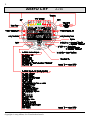
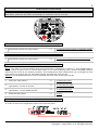
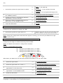
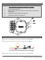
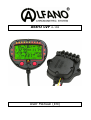
AStrO LVF A-165 User Manual (EN) 2 AStrO LVF Copyright 2005 Alfano, S.A. Tous droits réservés. A-165 3 Connection of the sensors Backside: 1 2 G-FORCE (lateral and longitudinal) A YELLOW or GYRO+G-FORCE (longitudinal) T° K1 or VOLTMETER B RED (1) : with A-361 + T° NTC1 or PRESSURE P1 T° K2 or LAMBDA or VALVE C RED (2) : with A-361 + T° NTC2 or PRESSURE P2 D GREEN MAGNETIC or INFRARED E BLUE SPEED F RPM (high sensitivity) G RPM (normal) H 2 BATTERIES (Type AA – Code IEC : R6) Information on data registration The system contains 2 data registration modes functioning automatically. 1) Mode 1 (PRINCIPAL) the system registers all data of varying sensors every 0.1 seconds and up to 95% of the memory’s capacity. NOTE: this mode is necessary for an in-depth analysis of the data with the software VISUALDATA. Afterwards, ALFANO automatically proceeds to mode 2. 2) Mode 2 (ENDURANCE) the system halts the registration every 0.1 seconds to leave space for the registration of the times with maximums and minimums (RPM, speed, temperatures, pressures) for every lap and for more than 24 hours. Copyright 2005 Alfano, S.A. All rights reserved. 4 Switching on the AStrO LVF Hold the two buttons « left and right » simultaneously pressed for two seconds. By releasing the buttons, the display appears and the system will ask you if you wish to activate the background screen or not. If you wish to activate it, press the right button to select the option « ON ». On the other hand, selecting the option « OFF » by pressing the left button or not doing anything, the device will automatically select the option « OFF » after a period of 2 seconds. Detection display of weak batteries When the batteries are weak, the system will detect it and the 4 bright temperature detector lights will start blinking rapidly one by one. When the device is in the START mode, the system will automatically return to the STOP mode ten minutes after weak batteries have been detected, and the message « CHANGE BAT » will appear. It is absolutely necessary to replace the batteries since the system will refuse to restart in the START mode and access the menu « Config System ». Note: a power cut while the ALFANO is in the START mode risks provoking a deterioration of the registered information. During the display of detected weak batteries, the other bright lights and the background light will automatically switch off in order to reduce energy consumption. Replacing the batteries Important: it is imperative to use quality batteries from big brand names to avoid these from running in the device. An interruption provoked by the battery’s acid cancels the warranty. Prior to replacing the batteries, always verify that the device is switched off, take off the lid of the battery compartment, remove the old batteries and afterwards place the two new batteries by verifying that the symbols "+" et "-" correspond to those engraved on the exterior of the compartment. Protective hoods IMPORTANT: the ports of the unused ports must always be closed by furnished caps. NOTICE: Please only use a screwdriver of the type TX20 (this type of screwdriver is provided to you together with your ALFANO). Make sure you do not turn the screws to tightly. You could damage the casing. Copyright 2005 Alfano, S.A. Tous droits réservés. 5 The STOP mode 3 possibilities of being in the STOP mode. 1 As soon as you switch on the AStrO LVF. 2 In de START mode, press the left button. 3 In the START mode, 10 seconds after the engine has stopped. NOTE: the STOP mode is the base of all other menus. Indeed, it is as of the STOP mode that it can be accessed either in the START mode or in the DATA menu or in the CONFIGURATION menu. START STOP DATA Menus CONFIGURATIONS Menus The information obtained in the STOP mode 1 Press the right button: >> The The The The best time. highest RPM. highest speed. highest temperatures / LAMBDA. For a period of 10 seconds 2 3 4 Press the same button another time before 10 seconds elapsed: Press the same button another time before 10 seconds elapsed: After 10 seconds or after having pressed the button (EXIT): >> Access to counter 1, total time (hour/minute), >> Access to counter 2, distance run (Km/Miles), >> Return to STOP. This screen will show you that: You have another 69 minutes of registration time in the PRINICIPAL mode. (PRINCIPAL mode, see page 3). Copyright 2005 Alfano, S.A. All rights reserved. 6 The START mode The information obtained during the course on the AStrO LVF: As soon as you pass the magnetic field: the screen, following the configuration of the AStrO LVF and connected sensors, will show you the following: - Time per lap Best time Previous time Target time Time gap (DELTA TIME) RPM + detector lights Speed - Temperatures + luminous alarm Pressures + luminous alarm Lambda + bright detector light Valve ON/OFF + bright detector light Connection engaged Battery tension Other information during the course. While you drive: (hour/minute), for a 1 Press the right button: >> Access to counter 1, total time period of 2 seconds. 2 Press the same button once more prior to the 2 seconds: >> Access to counter 2, distance run (Km/Miles), for a period of 2 seconds. 3 After the 2 seconds >> Return to START. NOTE: the 2 counters « 1 and 2 » are reset to zero only during the erasing of the data by the menu « 0.6 RESET ». This screen will show you: (16) (013) (129) Number of exits Number of laps of the last exit Number of laps (total) Copyright 2005 Alfano, S.A. Tous droits réservés. 7 DATA MENU While in the STOP mode: Successively Press the left button to access the menus 1 to 8 Menu 0.1 : 1 SYSTEM OFF Press the right button: Menu 0.2 : >> Switching off the device. RECALL 1 Press the right button: >> Access to all laps. 2 Press the right/left button: >> To consult the laps. 3 Press the right button 1 sec. on (VIEW): >> To analyze the lap by 0.1 second with the left and right buttons. 4 Press the left button 1 sec. on (EXIT): >> To exit. Menu 0.3 : Download Presenting the interface A-421 to execute the transfer of data to the PC or VISION A-181. Menu 0.4 : BEST LAPS 1 Press the right button: >> Access to the best lap of each exit. 2 Press the left/right button: >> To consult the best lap of each exit. 3 Press the right button 1 sec. on (VIEW): >> To analyze the lap by 0.1 second with the left and right buttons. 4 Press the left button 1 sec. on (EXIT): >> To exit. Copyright 2005 Alfano, S.A. All rights reserved. 8 Menu 0.5 : THEORICAL LAP NOTE: This menu is accessible if all laps consist of minimum 2 split times and that this number of split times is the same for all laps. 1 Press the right button: >> Access to the theorical lap. 2 Press the left/right button: >> To consult the best split times. 3 Press the left button 1 sec. on (EXIT) : >> To exit. NOTE: During the consultation of the split times, the text line at the bottom of the screen indicates the lap belonging to you. (see page 6) Menu 0.6 : 1 RESET Press the right button: Menu 0.7 : >> Execution of the deletion. COUNTERS « 3 et 4 » NOTE: The 2 counters « 3 and 4 » can only be reset to zero in this menu. 1 Press the right button: >> Access to counter 3, total time (hour/minute). 2 Press the right button: >> Reset to zero: time counter. 3 Press the left button: >> Access to (Km/Miles). 4 Press the right button: >> Reset to zero: distance counter. 5 Press the left button: >> To exit. Menu 0.8 : counter 4, distance run DEMO 1 Press the right button: >> Access to all laps. 2 Press the left/right button: >> To select the lap demo. 3 Press the right button: >> To start scrolling the selected lap in real time. 4 Press the left/right button: >> To exit. NOTE: Pressing the left button for 1 second at the start of any menu will make the system return to the STOP mode. Copyright 2005 Alfano, S.A. Tous droits réservés. 9 CONFIGURATION MENU While in the STOP mode, press the left button for 1 second: Afterwards, press the left button successively to access the menus 10 to 35. Menu 10 : 1 Successively Press the right button: Menu 11 : 1 STRIP NUMBER To configure the number of magnetic fields. >> To select the magnetic field on which the AStrO LVF must start. STRIP START Successively Press the right button: Menu 12 : >> STRIP LATENCY NOTE: This menu is only accessible when one single field is configured in menu 10. This configuration is useful: either to ignore one or several split times, or to avoid acquiring other infrared ALFANO emitters placed on the circuit at an untimely moment. This configuration does indeed allow you to program a time upon which the system will not react after having acquired the time per lap. NOTICE: this programmed time must be absolute less than that of the time per lap. 1 Press the right button: >> To enter the menu. 2 Continue to press or successively press the right button on the UP arrows: >> To increase the time. 3 Continue to press or successively press the right button on the DOWN arrows : >> To reduce the time. 4 Press the left button: >> To exit. Menu 13 : Best / Previous / Target In order to select the comparison mode of the last loop time: Copyright 2005 Alfano, S.A. All rights reserved. 10 1 Successively Press the right button to select: >> BEST : in the best lap >> PREVIOUS : in the second to last lap >> TARGET : in the programmed target time 2 To program the target time, wait 5 seconds at the TARGET position: >> So that the arrows would appear. 3 Continue to press or successively press the right button on the UP arrows: >> To increase the time. 4 Continue to press or successively press the right button on the DOWN arrows : >> To reduce the time. >> To exit. >> select: /10, /8, /6, /5, /4, /3, /2.5, /2, /1.5, /1.25 X1, X1.33, X1.6, X2, X4, X8. 5 Press the left button: Menu 14 : RPM Strock Configuring the coefficient to display the RPM: 1 Successively press the right button to: NOTE: During the configuration and while the engine is running, you can verify the RPM at the right bottom of the screen. Menu 15 : RPM LEDs Configuring the bright 10 LEDs functioning with the RPM: NOTE: the AStrO LVF contains 2 configuration methods. Method 1, configuration at 3 levels: A) B) C) Configuring the RPM (level 1) on LED 1. Configuring the RPM (level 2) on LED 7. Configuring the RPM (level 3) on LED 10. Afterwards, the AStrO LVF will calculate the RPM-interpolations for the other LEDs. 1 Press the right button: >> To enter the menu. 2 Press the right button on « LED 3 » : >> To confirm the selection of method 1. 3 Continue to press or successively press the right button on the UP arrows: >> To increase the RPM of LED 1. 4 Continue to press or successively press the right button on the DOWN arrows: >> To reduce the RPM of LED 1. 5 Press the left button: >> To regulate LED 7. Copyright 2005 Alfano, S.A. Tous droits réservés. 11 6 Continue to press or successively press the right button on the UP arrows: >> To increase the RPM of LED 7. 7 Continue to press or successively press the right button on the DOWN arrows: >> To reduce the RPM of LED 7. 8 Press the left button: >> To regulate LED 10. 9 Continue to press or successively press the right button on the UP arrows: >> To increase the RPM of LED 10. 10 Continue to press or successively press the right button on the DOWN arrows: >> To reduce the RPM of LED 10. 11 Press the left button: >> To exit. Method 2, configuration at 10 levels: A) B) C) D) E) F) G) H) I) J) Configuring Configuring Configuring Configuring Configuring Configuring Configuring Configuring Configuring Configuring the the the the the the the the the the RPM RPM RPM RPM RPM RPM RPM RPM RPM RPM (level (level (level (level (level (level (level (level (level (level 1) on LED 1. 2) on LED 2. 3) on LED 3. 4) on LED 4. 5) on LED 5. 6) on LED 6. 7) on LED 7. 8) on LED 8. 9) on LED 9. 10) on LED 10. 1 Press the right button: >> To enter the menu. 2 Press the left button, followed by pressing the right button on « LED 10 »: >> To confirm the selection of method 2. 3 Continue to press or successively press the right button on the UP arrows: >> To increase the RPM of LED 1. 4 Continue to press or successively press the right button on the DOWN arrows: >> To reduce the RPM of LED 1. 5 Press the left button: >> To regulate LED 2. Continue the same operations to regulate the other LEDs one by one until LED 10. 6 Press the left button: Menu 16 : >> To exit. ALARM T° Regulating the 4 bright detector lights, LOW temperature and HIGH temperature of: T1 T2 T1 T2 « « « « K» K» NTC » NTC » Copyright 2005 Alfano, S.A. All rights reserved. 12 1 Press the right button to enter the menu and to regulate: >> The LOW level of: T1 « K ». 2 Continue to press or successively press the right button on the UP arrows: >> To increase the level. 3 Continue to press or successively press the right button on the DOWN arrows: >> To reduce the level. 4 Press the left button to regulate: >> The HIGH level of: T1 « K ». 5 Continue to press or successively press the right button on the UP arrows: >> To increase the level. 6 Continue to press or successively press the right button on the DOWN arrows: >> To reduce the level. 7 Press the right button to regulate: >> The LOW level of: T2 « K ». Continue the same operations to regulate the levels of: T2 « K » : LOW and HIGH T1 « NTC » : LOW and HIGH T2 « NTC » : LOW and HIGH 8 Press the left button: >> To exit. NOTE: in the STOP and START modes: The temperatures are lower than the LOW levels The temperatures higher than the HIGH levels Menu 17 : = = The detector lights REMAIN ILLUMINATED. The detector lights ARE BLINKING. PRESSURES Activating « ON/OFF » the pressure sensors or not, and regulating the 2 detector lights, LOW pressure and HIGH pressure: P1: Pressure 1 P2: Pressure 2 1 Press the right button: >> To enter the menu. 2 Successively press the right button: >> To select sensor P1 or to deactivate it 2 Bar, 5 Bar, 10 Bar, OFF. 3 Press the left button: >> To position yourself at P2. 4 Successively press the right button: >> To select sensor P2 or to deactivate it 2 Bar, 5 Bar, 10 Bar, OFF. The menus below will be accessible if the sensors have been activated. 5 Press the left button to regulate: >> The LOW level of P1. 6 Continue to press or successively press the right button on the UP arrows: >> To increase the level. 7 Continue to press or successively press the right button on the DOWN arrows: >> To reduce the level. Copyright 2005 Alfano, S.A. Tous droits réservés. 13 8 Press the left button to regulate: >> The HIGH level of P1. 9 Continue to press or successively press the right button on the UP arrows: >> To increase the level. 10 Continue to press or successively press the right button on the DOWN arrows: >> To reduce the level. 11 Press the left button to regulate: >> The LOW level of P2. Continue the same operations to regulate the levels of: P2: LOW and HIGH 12 Press the left button: >> To exit. NOTE: in the STOP and START modes: The pressures are lower than the BAD levels The pressures are higher than the HIGH levels = = the detector lights ARE BLINKING. the detector lights REMAIN ILLUMINATED. NOTICE: The activated pressure sensors replace the temperature sensors « NTC ». P1 activate takes over the place of T1 « NTC » P2 activate takes over the place of T2 « NTC » Menu 18 : SPEED Config Configuring the length of the wheel circumference: NOTE: as for the AStrO LVF, it is necessary to connect a speed sensor. 1 Press the right button: >> To enter the menu. 2 Continue to press or successively press the right button on the UP arrows: >> To decrease the circumference. 3 Continue to press or successively press the right button on the DOWN arrows: >> To increase the circumference. 4 Press the left button: >> To exit. NOTE: the measure is represented either in "metric" millimeters or in "imperial" inches according to the configuration in menu 31. IMPORTANT: It is absolutely necessary to connect the speed sensor to draw the trajectory with the software "VISUALDATA". Menu 19 : GEARBOX Configure the transmission ratios. NOTE: the configuration is done while driving normally. 1 Press the right button: >> To enter the menu. 2 Drive in 1st gear: >> The system automatically configures the ratio of box n°1. Copyright 2005 Alfano, S.A. All rights reserved. 14 3 Afterwards, when the system displays number 2, engage the 2nd gear: >> The system automatically configures the ratio of box n°2. 4 Afterwards, when the system displays number 3, engage the 3rd gear: >> The system automatically configures the ratio of box n°3. Continue the same operations to configure the other speeds. 5 Press the left button « END »: >> To terminate and exit. IMPORTANT: It is absolutely necessary to connect the speed sensor and the RPM sensor to be able to configure the gears of speed box. Menu 20 : G-FORCE / GYRO Calibration of the sensor: NOTE: prior to calibrating the AStrO LVF, place the vehicle on a horizontal surface. 1 Press the right button: >> To enter the menu. 2 Press the right button: >> To calibrate the AStrO LVF. 3 Press the left button: >> To exit. IMPORTANT: It is absolutely necessary to connect the G-FORCE sensor to draw the trajectory with the software "VISUALDATA". Menu 21 : LAMBDA ON / OFF Activate « ON/OFF » or not the LAMBDA sensor: NOTE: when the LAMBDA sensor is in the « ON » position, the 10 high LEDs of the AStrO LVF will solely function with the Lambda probe. Poor Normal Very good 1 Press the right button: >> To enter the menu. 2 Successively press the right button: >> To activate « ON/OFF » or not the LAMBDA sensor. 3 Press the left button: >> To exit. NOTICE: When the LAMBDA sensor is activated « ON », this sensor will replace the sensor of temperature T2 « k » or the VALVE sensor, according to the previous configuration. Menu 22 : VALVE ON / OFF Activate « ON/OFF » or not the VALVE sensor: Copyright 2005 Alfano, S.A. Tous droits réservés. 15 1 Press the right button: >> To enter the menu. 2 Successively press the right button: >> To activate « ON/OFF » or not the VALVE sensor. 3 Press the left button: >> To exit. NOTICE: When the VALVE sensor is activated « ON », this sensor will replace the sensor of temperature T2 « k » or the LAMBDA sensor, according to the previous configuration. Menu 23 : VOLTMETER ON / OFF Activate « ON/OFF » or not the VOLTAGE sensor: 1 Press the right button: >> To enter the menu. 2 Successively press the right button: >> To activate « ON/OFF » or not the VOLTM sensor. 3 Press the left button: >> To exit. NOTICE: When the VOLMETER sensor is activated « ON », this sensor will replace the temperature sensor T1 « k ». Menu 24 : ------------ EMPTY Menu 25 : ------------ EMPTY Menu 26 : ------------ EMPTY Menu 27 : NAME Edit To make your name or a sentence of maximum 21 characters appear on the screen: 1 Press on right button : >> To enter in the menu. 2 Press successively the right button : >> To choose the letter/the number needed. 3 Press the left button : >> To confirm and position on the following case. 4 Press the left button after the 21st case : >> To exit. NOTE: Your name (or the sentence) will appear on the screen on activation and on extinction of the system during 4 seconds. Menu 28 : PEAK Configure the high value hangover time « RPM » and « speed » during the course: 1 Press the right button: >> To enter the menu. 2 Successively press the right button: >> To regulate the hangover time of the RPM, OFF at 4.4 seconds. Copyright 2005 Alfano, S.A. All rights reserved. 16 5 Press the left button: >> To select: SPEED. 6 Successively press the right button: >> To regulate the hangover time of the SPEED, OFF at 4.4 seconds. 7 Press the left button: >> To exit. Menu 29 : DISPLAY MASK Hiding the information on the screen during the course: 1 Press the right button: >> To enter the menu « TIME ». 2 Successively press the right button: >> To select: ON / OFF. 3 Press the left button: >> To enter the menu « DELTA TIME » 4 Successively press the right button: >> To select: ON / OFF. 5 Press the left button: >> To enter the menu « REF. TIME» 6 Successively press the right button: >> To select: ON / OFF. 7 Press the left button: >> To enter the menu « RPM ». 8 Successively press the right button: >> To select: ON / OFF. 9 Press the left button: >> To enter the menu « SPEED ». 10 Successively press the right button: >> To select: ON / OFF. 11 Press the left button: >> To exit. NOTE: As soon as the AStrO LVF is in the START mode, all configured information OFF will be hidden. Menu 30 : C° / F° Configuring the temperature measuring unit: 1 Press the right button: >> To enter the menu. 2 Successively press the right button: >> To select: CELCIUS / FAHRENHEIT. 3 Press the left button: >> To exit. >> To enter the menu. Menu 31 : METRIC / IMPERIAL Configuring the distance measuring unit: 1 Press the right button: Copyright 2005 Alfano, S.A. Tous droits réservés. 17 2 Successively press the right button: >> To select: METRIC / IMPERIAL. 3 Press the left button: >> To exit. NOTE: Menu 32 : METRIC = For the speed: Km/h For counters 2 & 4: meters/KM. For the adjustment of the wheel circumference: mm IMPERIAL = For the speed: Miles/Hour For counters 2 & 4: Miles For the adjustment of the wheel circumference: Inch POWER : 1 / 2 / 3 Configuring the luminosity of the LEDs and background lighting of the AStrO LVF: 1 Press the right button: >> To enter the menu. 2 Successively press the right button: >> To select: the POWER : 1, 2 or 3. 3 Press the left button: >> To exit. NOTE: The stronger the detector lights and the background light are, the faster the batteries discharge. Menu 33 : POWER : INTERN / EXTERN Configuring the power source of the AStrO LVF: - Either the AStrO LVF takes its power from its own batteries. In this case, it is advisable to use, with an eye toward energy efficiency of the batteries, the mode: INTERN. = the AStrO LVF automatically shuts off after 10 minutes of non-use. - Or the AStrO LVF takes its power from the battery of the vehicle with the A-431. In this case, you can select the mode: EXTERN. = The AStrO LVF never shuts off but is placed in hibernation mode after 30 minutes of non-use and is automatically activated when the engine restarts. 1 Press the right button: >> To enter the menu. 2 Successively press the right button: >> To select: INTERN / EXTERN. 3 Press the left button: >> To exit. Menu 34 : DEFAULT Restoring the AStrO LVF with the factory parameters. 1 Press the right button: >> To enter the menu. 2 Press the right button: >> To confirm the restoration of the AStrO LVF. Copyright 2005 Alfano, S.A. All rights reserved. 18 3 Press the left button: Menu 35 : >> To exit. VERSION This menu gives you the possibility of seeing the serial number and the version of the software of your AStrO LVF. NOTE: Pressing the left button for 1 second at the start of any menu will make the system return to the STOP mode. Copyright 2005 Alfano, S.A. Tous droits réservés. 19 Configuration of the RPM-amplifier of the AStrO LVF The installation procedure consists of 4 phases I. Connecting the power cables. II. Finding the RPM-signal on the majority of motor ignitions and connecting the RPM-cable. III. Configuring the RPM-amplifier of the AStrO LVF. IV. Configuring the display of the AStrO LVF. I. Connecting the power cables. F: black wire: on the negative pole (12/24 volt) of the battery. Length: 350 cm G: red wire: on the positive pole (12/24 volt) of the battery. Length: 350 cm RPM H: yellow wire: connects with the ignition or the calculator box. Length: 350 cm Copyright 2005 Alfano, S.A. All rights reserved. 20 II. Finding the RPM-signal on the majority of motor ignitions and connecting the RPM-cable. A) Classical high-tension coil: Connecting the « yellow » cable to the negative terminal of the coil. « Yellow » cable B) High-tension coil (static double-contact) with 2 or more cables: One single wire is capable of providing you with the RPM-signal on the majority of ignitions. It must be located in order to electrically connect the « yellow » wire. Trick: to avoid damaging the insulation of the wires connected to the coil to locate the RPM-signal, use a needle (of the designer type) and prick it into one of the wires. Make sure that the needle skewers the wire well in the center in order to obtain the electrical contact. Strip the « yellow » wire of the AStrO LVF and twist it around the needle. WATCH OUT for short circuits. Launch the engine at a slow pace and observe the red LED in the transducer box. The LED must light up after contact with the wire carrying the RPM-signal. If this is not the case, repeat the operation on the other wires until the LED lights up. C) High-tension coil placed on the spark plug with 2 or more cables: These wires originate from a terminal box. NOTICE: the connection must be made from the side of the terminal box and not from the side of the coil. The procedure to locate the wire carrying the RPM-signal takes place in the same manner as for the high-tension coil (static double-contact), explained above. Copyright 2005 Alfano, S.A. Tous droits réservés. 21 D) Electronic control unit CALCULATOR: On calculator boxes such as GM, HEI or MSD you will find a special terminal called « TACH ». Connect it with the « yellow » cable. «Yellow» cable Electronic control unit CALCULATOR To guarantee a lasting operation, make sure the wiring is done correctly. III. Configuring the amplifier RPM of the AStrO LVF Take off the lid from the transducer box (4 screws). 1) 2) Make the engine run at a slow pace, (DO NOT ACCELERATE) the red signal must blink. Afterwards, press on the small push-button for about 2 seconds Bright RPM-signal Push-button IV. Configuring the display of the AStrO LVF. This operation consists of displaying the RPM correctly in your ASTRO LVF. 1) 2) Make the engine run at a slow pace. (DO NOT ACCELERATE) In the « RPM » configuration menu of your ASTRO LVF (MENU 14), you must select the correct unit with the right button in order to display the right RPM. (/10) (/8) (/6) (/5) (/4) (/3) (/2.5) (/2) (/1.5) (/1.25) (X1) (X1.33) (X1.6) (X2) (X4) (X8) These units will divide or multiply the impulses originating from the RPM-module and the result will be displayed in the top right corner of the screen. By knowing your RPM at a slow pace, it suffices finding it on your ASTRO LVF. Copyright 2005 Alfano, S.A. All rights reserved. 22 ALFANO S.A. Rue de l’ Industrie, 3b – 1400 NIVELLES www.alfano.com Copyright 2005 Alfano, S.A. Tous droits réservés.