1
800168-0A
Sep. 2008
USER’S MANUAL
Digital High Speed
GXLink
SP-630
(blank page)
Copyright © 2008 NAC Image Technology,Inc.
The copyright for this document is owned by NAC
Image Technology ,Inc.
The copyright for the software described in this
document is owned by NAC Image Technology,Inc.
Trademark
MEMRECAM is a trademark of NAC Image
Technology Inc.
Microsoft Windows, Windows 2000, and Windows
XP are registered trademarks of Microsoft USA, Inc.
TIFF is a registered trademark of Adobe Systems
Incorporated.
Other names of companies and products are
trademarks or registered trademarks of other
companies.
MEMRECAM GXLink
SP-630 Manual
Sep 2008
Reference Number 800168-0A
This document describes GXLink version 1.14.
Any copying, duplication or reproduction of any or
this entire document without written permission
from NAC Image Technology, Inc. is prohibited.
The contents of this document may be changed
without prior notice.
(blank page)
Please Read Carefully Before Using
Safety Precautions
Before using, please read the following precautions. Depending on the device, the
following symbols and warnings are shown for items requiring particular safety
precautions during handling. For these notations, please read the warnings before
beginning operation.
DANGER
If the indications shown are ignored, dangerous conditions could result
in death or serious injury.
WARNING
If the indications shown are ignored, potentially dangerous conditions
could result in death or serious injury.
CAUTION
If the indications shown are ignored, potentially dangerous conditions
could result in slight or moderate injury. This is also a warning sign
of unsafe operation and indicates the potential of damage to this device
or connected devices.
Operating Precautions
Safety alert symbol
This is the safety alert symbol. This symbol alerts you or others to the
danger and/or items or operating concerns relating to the use of this
device.
This mark is also used when there is important information relating to
operation. Read the message by this symbol carefully and follow the
instructions for safe and appropriate use of this device.
(00168)
i
Grounding terminal symbol
This symbol indicates the site of a protective grounding terminal. If
not grounded, electrical shock could be received from the metallic and
other parts of this device. Due to this danger, please make sure it is
grounded. When connecting to an electric outlet using a 3P-2P convertible
plug, connect with the outside grounding terminal of the convertible plug
grounding wire.
Warning
Power switch must be turn off before connecting or disconnecting cables.
If the cables are connected or disconnected leaving the power switch ON,
it may cause electrical shock as well as damage on the equipment.
High voltage warning
When replacing fuses, conduct with the power cable unplugged from the
electric plug. Do not open the cover. Depending on the device, there may
be parts that generate high voltage internally so opening the cover could
result in electrical shock.
There may be problems with the conditions and circumstances of use for this device
not stated above. As a result, sufficiently understand the general provisions noted
in the Operation Manual of this device before using. Also, directly contact the
retail outlet as soon as possible if there are any questions about this device.
ii
(00168)
Provisions Regarding Use and Warranty
NAC Image Technology provides a warranty for operation of the software product within the
following limits and operation under normal conditions of use described in the Operation Manual.
NAC Image Technology does not offer any other warranty related to this product.
1. Warranty
If this software does not function normally at delivery due to a defective medium or other
reason, it will be replaced free of charge.
2. Support Services
NAC Image Technology will provide essential information on bugs and upgrades relating to
our software. This service will be available for a period of one year from the date of
software delivery.
3. Licensing
NAC Image Technology shall be liable for this software only as stated in 1. and 2. above.
NAC Image Technology shall bear no liability for damage occurring as the result of use of
this software.
Methods of use for this software are explained, and this Operation Manual is complete but
NAC Image Technology shall bear no liability for damage occurring as the result of any
omissions.
4. Copyrights and Rights of Use
Copyright for this software is retained by NAC Image Technology. NAC Image Technology
authorizes customers the use of this software under the following conditions.
5. Range of Use
This software may not be used on multiple computers simultaneously.
6. Duplication Limitations
Other than for the purposes of customer backup, this software may not be copied in part
or in its entirety.
7. Third Party Use
Third party usage by any method such as lease, grant or transfer of this software or copies
is not allowed.
8. Liability after Modifications or Upgrades
If there are modifications or upgrades to this software not administered by NAC Image
Technology , NAC Image Technology does not guarantee it’s normal operation. Also, NAC Image
Technology shall bear no liability for damage occurring due to modifications or upgrades
on this software.
(00168)
iii
Introduction
By using the GXLink (this software), MEMRECAM GX or fx camera can be
control via the network, and digital images photographed can be stored
on a PC.
This Operation Manual describes the system for operation, including
initial settings and applications for using these GXLink features.
Read this document and become familiar with the operation before
photographing.
iv
(00168)
Table of Contents
Please Read Carefully Before Using··································· i
Provisions Regarding Use and Warranty································ iii
Introduction························································· iv
Table of Contents···················································· v
1 Overview··························································· 1-1
1.1 Basic Functions ·············································· 1-2
1.2 Overview of Operations ······································· 1-3
1.3 File Types ··················································· 1-4
2 Installation······················································· 2-1
2.1 Installation Procedures ······································ 2-2
2.3 Uninstall Procedures ········································· 2-9
3 Operation·························································· 3-1
3.1 Start ························································ 3-2
3.2 Camera Registration ·········································· 3-4
3.3 Camera Connections ··········································· 3-6
3.4 Menus ························································ 3-8
3.5 Toolbar ······················································ 3-19
3.6 Recording・Playback ·········································· 3-27
3.7 Parameter Settings ··········································· 3-32
3.8 Downloading Images ··········································· 3-54
3.9 Saving Images on USB ········································· 3-60
3.10 Data Cartridge Image Input ·································· 3-65
3.11 Play File Images ············································ 3-66
3.12 Adjusting the Quality of Camera Image Files ················· 3-68
3.13 AVI Settings ················································ 3-76
3.14 Rotate Image・Reverse Image ································· 3-81
3.15 Convert Image Format ········································ 3-84
3.16 Frame Rate Conversion ······································· 3-88
3.17 Sync Display ················································ 3-89
3.18 T=0 Setting ················································· 3-91
3.19 View・Measure ··············································· 3-98
3.20 Other Functions ············································· 3-107
3.21 Option Settings ············································· 3-113
4 Troubleshooting···················································· 4-1
4.1 Troubleshooting ·············································· 4-2
5 Recording Settings················································· 5-1
5.1 Recording Overview ··········································· 5-2
5.2 External Synchronized Recording ······························ 5-3
5.3 Multi Camera Synchronized Recording with IRIG-B Signals ······ 5-7
5.4 GX Multi Camera Synchronized Recording with the GX-HUB ······· 5-9
5.5 Multi Camera Synchronized Recording with a Mix of fx and GX ·· 5-10
5.6 Exposure Phase Shift Recording ······························· 5-11
5.7 Event Recording ·············································· 5-12
(00168)
v
5.8 Burst Recording ·············································· 5-12
5.9 Multi Trigger Recording ······································ 5-13
6 System Settings (GXUtility) ········································ 6-1
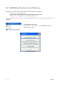
6.1 GXUtility Contents and Startup ······························· 6-2
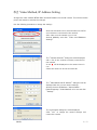
6.2 Video Method, IP Address Setting ····························· 6-3
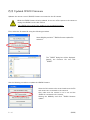
6.3 Updated JPAD3 Firmware ······································· 6-5
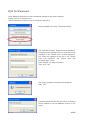
6.4 Set Password ················································· 6-7
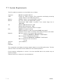
7 Specifications ····················································· 7-1
7.1 System Requirements ·········································· 7-2
Appendix A ··························································· A-1
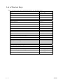
List of Shortcut Keys ············································ A-2
Appendix B ··························································· B-1
File Conversion Setting (FCV files) ······························ B-2
Appendix C ··························································· C-1
Parameter File Settings (prm files) ······························ C-2
vi
(00168)
1
Overview
(00168)
1 - 1
1.1 Basic Functions
The GXLink can perform the following functions.
■Control the MEMREACM GX or fx camera (preview, record, playback, download)
■Play camera image files (MCFF, CIF), adjust image quality, convert formats (AVI, TIFF, BMP,
JPEG)
■Play image files (AVI, TIFF, BMP, JPEG)
■Measure coordinates(camera preview images, camera image files, image files)
Images can be zoomed or scrolled to view.
Simultaneous display is possible, which involves simultaneously displaying images for
multiple designated items (cameras or files).
Video playback allows the playback range, playback direction and playback speed to be
specified.
This does not control the MEMRECAM ci camera but downloaded images (CIF) can be
handled in the same manner as MCFF (MEMRECAM Camera File Format). Also, scenes
from data cartridges where ci camera images are saved can be captured in the MCFF
format.
If the GX-HUB option is used, synchronized high precision photography can be performed
with the GX cameras.
If the M-HUB option is used, synchronized high precision photography can be performed
with the fx cameras.
1 - 2
(00168)
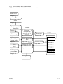
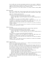
1.2 Overview of Operations
An overview of the flow of GXLink operations is shown below.
Start GXLink
Page 3-2
Register and select
camera
Page 3-4
Set photographic
parameters
Page 3-32
Recording
Display
Playback
(verify image)
Same image as in the
camera VF
Page 3-27
Page 3-30
Adjust playback
image quality
Display MCFF image
Page 3-68
Page 3-66
Zoom
Scroll
Page 3-99
Download
Page 3-54
MCFF
MCFF
Display file image
AVI, BMP, TIFF, JPEG
Page 3-66
Measure
coordinates
File image
Convert format
Page 3-84
AVI
BMP
JPEG
TIFF
Coordinates file
Page 3-101
End
(00168)
1 - 3
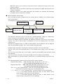
1.3 File Types
1. Camera Data (IMGE.DAT)
Camera data files are assigned the file name of IMGE.DAT when the MEMRECAM ci series
camera recorded images are saved as image files in the data cartridge. Multiple recorded
images are saved in IMGE.DAT. The data cartridge rapidly carries out the storage format for
the MEMRECAM ci recorded image.
With the GXLink, recorded images from the camera data file IMGE.DAT can be captured on
the camera image file (MCFF) for each scene.
2. Camera Image Files (MCFF,CIF)
Camera image files include MCFF (MEMRECAM Camera File Format) and CIF(CI File).
A MCFF is a single scene image file recorded on a MEMRECAM GX/fx/ci series camera with
an extension of .mcf.
A CIF is a single scene image file recorded on a MEMRECAM ci series camera with an
extension of .cif.
MCFF and CIF contain the image recorded with the camera as well as photographic
information at the time of recording.
With the GXLink, the image quality of the camera image loaded (MCFF, CIF) is adjusted and
can be saved after conversion to a standard image file (AVI, TIFF, BMP, JPEG).
3. Video Files (AVI)
AVI files are a type of multimedia file used with Microsoft Video for Windows that have an
extension of .avi. The quantity of data on the AVI files can be compressed using a special
program (codec).
Codec corresponding to the image compression method is required to display AVI file images
but GXLink does not use codec, and can save and playback AVI files with the Motion JPEG
method.
Additionally, GXLink can conduct AVI file storage/playback using compression/extension
codec registered in Windows.
4. Still Image Files (TIFF,BMP,JPEG)
With the GXLink, images for the designated frame range for the camera image file (MCFF,
CIF) can be converted to standard still image files in a TIFF, BMP, JPEG format for each
frame and saved, and the image information or photographic information when recorded can
be saved in a scene information file.
A number can be added to the file name of the still image file designated when converted and
saved.
The number added to the file name is increased for each frame, using 0 for the starting frame
during conversion and saving.
The GXLink loads the converted and saved still image file and the scene information file for
playback as a video.
5. Scene Information Files (TXT)
With the GXLink, the conversion settings when converted and saved as well as the
photographic information for MCFF recording can be saved in the scene information file (text
file TXT) with the same name as the image file. The GXLink displays the information for the
frame range of the scene information file during video playback of the still image file as the
loaded frame number.
1 - 4
(00168)
6. Conversion Settings Files (FCV)
With the GXLink, image quality adjustment is performed on the camera image file (MCFF, CIF)
and the settings can be saved in the conversion settings file (FCV). With the FCV file settings
loaded, the MCFF image quality can be set.
Additionally, the FCV file settings used normally can be registered as the default settings.
Refer to the description in Appendix B for details on FCV files.
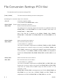
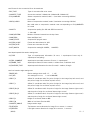
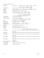
7. Parameter Settings Files (PRM)
With the GXLink, the camera parameters can be saved as the file settings (PRM). Details of
the parameter files saved can be saved to another camera.
Refer to the description in Appendix C for details on PRM files.
8. Coordinate Point Files (CSV)
With the GXLink, the coordinates for the live image displayed or the file image are measured
and the measured coordinate data can be output to the CSV file.
Refer to page 3-87 for details.
9. Waveform Data Files (NWF)
Use the GXLink Waveform Input Software option to input analog data (waveform data) during
recording and save the waveform data to the file (NWF). GXLink can synchronize and display
the graph of the waveform data for this NWF file with the image. Additionally, the waveform
data can be printed and the CSV output.
(00168)
1 - 5
(blank page)
1 - 6
(00168)
2
Installation
(00168)
2 - 1
2.1 Installation Procedures
An authorized user of the Windows Administrators group should log on.
Insert the included CD into the CD-ROM drive when other applications are not running.
The MEMRECAM GXLink installation will start automatically.
■ For an FC-AL connection, before installing the MEMRECAM GXLink, the FC-AL host bus
adapter driver should be installed by attaching the FC-AL host bus adapter to the PC.
■ Perform installation to connect the Gbit (1000BASE-T) K5, RX-6G and RX-5G camera by
installing the iSCSI Initiator and setting the PC network by referencing the supplemental
camera manual "Gbit Connectivity".
The "Gbit Connectivity" refers to the use of the fxLink as the camera control software, but
the GXLink should be installed instead of the fxLink.
■ For a TCP/IP MEMRECAM connection, "TCP/IP network optimization" is performed when
the GXLink is installed. Please install to a PC connected to a LAN (Ethernet HUB) or a
MEMRECAM that is turned on. During the GXLink installation, if the PC is not connected to
a LAN or a MEMRECAM, you will be required to perform "TCP/IP network optimization"
again when the MEMRECAM is connected. Click on "TCP/IP network optimization" in the
Windows start menu and restart the PC after setting.
2 - 2
(00168)
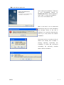
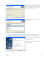
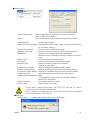
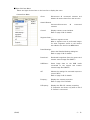
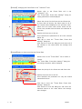
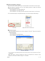
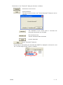
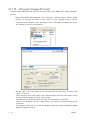
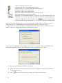
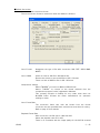
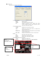
■ Install GXLink Application
Upon starting the installation, "Welcome
to the InstallShield Wizard for
MEMRECAM GXLink" will be displayed.
Click "Next" to start the installation.
(The screen shows Windows XP)
When a user who is not an authorized
administrator logs on to start installation,
the message shown to the left is
displayed. An authorized administrator
must log on and perform the GXLink
installation.
If the same version or another version of
GXLink has already been installed, a
warning
regarding
overwriting
the
installation is shown. We recommend
uninstalling
the
previously
installed
GXLink before installation.
(00168)
2 - 3
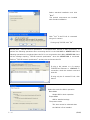
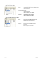
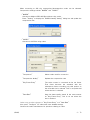
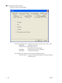
Select standard installation and click
"Next".
The optimal components are installed
with standard installation.
Click "Yes" if the FC-AL is connected
using an fx camera.
If using only TCP/IP, click "No".
At this point, "TCP/IP network optimization" is conducted with TCP/IP or Gbit connections, so
perform the following operations after connecting the PC to the LAN HUB or MEMRECAM. If the
following operations are conducted when the PC is not connected to the LAN or MEMRECAM, there
will be message requiring "TCP/IP network optimization" when the MEMRECAM is connected.
Perform "TCP/IP network optimization" at that point and restart the PC.
If using a GX camera or a fx camera
TCP/IP(Fast Ethernet or 1000BASE-T)
connection, check the network used and
click OK.
If using only the fx camera FC-AL, click
Cancel.
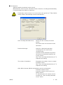
Select the mode for GXLink operation.
Basic Mode
Simple GUI for basic operation.
Expert Mode
GUI for detailed settings.
The present mode
This item cannot be selected when
the GXLink is first installed.
2 - 4
(00168)
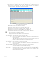
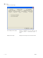
If changing the drive or folder for installing
the program, click "Browse" and set the
folder for installing the program. After
designating the folder, click "Next".
Designate the name of the program folder
and click "Next".
※ Designating a default program folder has already been described in this manual. If designating a
different folder, change the menu display for the startup method to the designated setting.
Click "Finish" when the dialog for setup
complete is displayed.
The computer must be restarted before
using the program.
(00168)
2 - 5
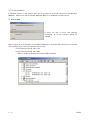
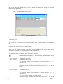
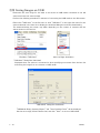
2.2 Verify Hardware
If Windows detects a new camera when the fx camera has a FC-AL connection with Windows
2000/XP, "Welcome to the Found New Hardware Wizard" is displayed to install a driver.
○ Windows2000
If there are two or more new cameras
connected, all of the cameras should be
verified.
After verifying all of the cameras, use the Device Manager to verify that the cameras are connected.
The following screen shows two K3 with the PC (OS).
fx-K3 (firmware ver1.62, CID 1116)
fx-K3 (firmware ver1.62, CID 1248)
CID is a number to identify the camera (DRP) individual.
2 - 6
(00168)
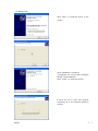
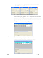
○ Windows XP
Click "Next" to install the driver to the
system.
Once installation is complete,
"Completing the Found New Hardware
Wizard" will be displayed.
Click "Finish" to close the window.
If there are two or more new cameras
connected, all of the cameras should be
verified.
(00168)
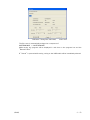
2 - 7
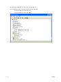
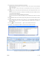
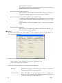
Use the Device Manager to verify camera connections.
In the following screen, verify the two K3 with the PC (OS).
fx-K3 (firmware ver1.62, CID 1116)
fx-K3 (firmware ver1.62, CID 1248)
2 - 8
(00168)
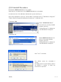
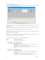
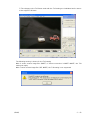
2.3 Uninstall Procedures
Uninstall the MEMRECAM GXLink if not needed.
Saved data is not deleted even if the MEMRECAM GXLink is uninstalled.
An authorized user of the Windows Administrators group should log on.
Close other applications, open the "Control Panel" and double click on "Add/Remove Programs"
("Add or Remove Programs And Windows Components" on Windows XP).
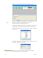
○ Windows 2000
Select "MEMRECAM GXLink"
from the list of currently installed
programs and click
"Change/Remove" to display the
"Uninstall GXLink" dialog box.
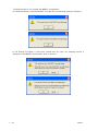
○ Windows XP
Select MEMRECAM GXLink from
the list of currently installed
programs and click
"Change/Remove" to display the
"Uninstall GXLink" dialog box.
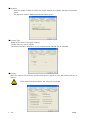
Click "Yes" to uninstall.
The GXLink cannot be uninstalled if
running.
The dialog shown to the left will be shown if
the GXLink is running, so follow the
instructions to proceed.
(00168)
2 - 9
(blank page)
2 - 10
(00168)
3
Operation
(00168)
3 - 1
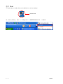
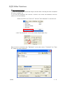
3.1 Start
To start GXLink, double click on the GXLink icon on the desktop.
Double click
Or, start by clicking
3 - 2
start → All Programs → MEMRECAM GXLink → GXLink.
(00168)
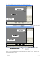
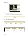
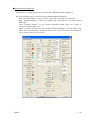
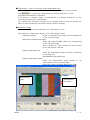
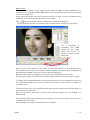
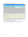
The GXLink GUI offers a basic mode and a more detailed expert mode.
Item Toolbar
Image Monitor
Main Toolbar
Status Bar
[Start screen:Basic Mode]
Item Toolbar
Image Monitor
Main Toolbar
Camera Parameter Toolbar
[Start screen:Expert Mode]
Status Bar
Switch to and from the Basic Mode and the Expert Mode using "Option" on the "Settings" menu.
Refer to page 3-100 for details.
(00168)
3 - 3
3.2 Camera Registration
With GXLink, it is not necessary to register cameras to control the MEMRECAM GX series
but camera registration allows a desired nickname to be assigned to a camera.
If a camera is not registered, the camera nickname becomes the camera type and the CID.
To control a MEMRECAM fx series camera, the camera used (DRP) must be registered in
advance. The registered DRP information is saved in the settings file.
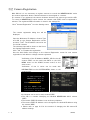
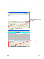
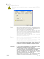
Click "Camera Registration" from the Settings menu.
The camera registration dialog box will be
displayed.
Input the Nickname, IP Address, Camera Type
and CID on the Camera Registration screen
and click "Add". The IP address cannot be set
for the GX cameras.
The nickname input will be shown on the list on
the Camera Registration screen.
Click "OK" to complete the registration.
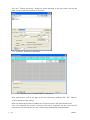
Use the Add, Delete and Change on the Camera Registration screen for new camera
registrations, and delete or change cameras registered.
Verification of the IP Address, MODEL, CID for the GX
camera (DRP) can be made with INFO on the SYS
MENU shown on the JPAD3 (remote control) or the
start screen.
Verification of the fx series can be made with
INFORMATION on the SYSTEM MENU shown on the
camera menu.
JPAD3 INFO
GX Series Start Screen
fx Series INFORMATION
* A nickname can be set for each camera (DRP).
* The CID is a number identifying an individual MEMRECAM GX/fx camera
(DRP).
* The camera (DRP) IP Address is set at factory shipment.
* The camera (DRP) IP Address can be changed to the desired IP address using
the camera (DRP).
* Please refer to page 6-2 for the method of changing the GX camera IP
address settings.
3 - 4
(00168)
3.3 Camera Connections
Caution
・When connecting the fx camera, confirm that the connections between the
camera-PC "100B-T (ethernet) / FCAL (fiber channel) / Gbit
(1000BASE-T)" and the settings menu connection method match.
・Confirm that the camera and PC are properly connected.
・Confirm that the camera is operational.
While the GX camera connections are set at TCP/IP,
select the tabs "Option" and "Connect Type" on the
"Settings" menu for the initial camera connection
method for connecting fx cameras.
Select "TCP/IP Connection" if 100B-T (Ethernet),
"FC-AL Connection" if FCAL (fiber channel) or "Gbit
Connection" if Gbit (1000BASE-T).
Click "Attach the camera"
camera.
on the Item Toolbar to begin connections with the
The "Attach the camera" dialog box will be
displayed, and the GX camera connected to the
PC and the FX camera registered will be displayed.
When there is only one camera registered and
communication has been established with that
registered camera, the "Attach the camera" dialog
box will not be displayed, but the following page
will be displayed.
Cameras that can be connected are sorted for
display. Check the box on the left side of the list.
For "fx camera not connected to a PC" or "fx/GX
camera used on another PC", there will be a red X
on the camera just before the nickname.
Uncheck any boxes where there is a check on camera
not connected. Click OK to start connecting the
cameras checked.
(00168)
3 - 5
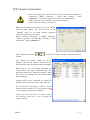
Once "Attach the camera" is started, the specified camera is added to the Item List, and the
camera nickname (Name), camera type, camera head number (CAMERA) and camera status
are displayed.
The status display for the Item List is updated each time the camera status is changed, and
the camera status is displayed.
Once the camera connections are completed, the camera live images are displayed on the
monitor.
The connected
cameras are added
to the item list.
3 - 6
(00168)
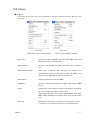
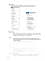
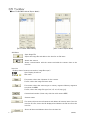
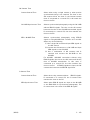
3.4 Menus
■File Menu
The items on the file menu vary according to the item selected (camera, file) from the
Item List.
File menu
(when camera item (GX) selected)
File menu
(when file item (MCFF) selected)
・Open File…
Opens the image file (MCFF, CIF, AVI, TIFF, BMP, JPEG) and
adds the file item to the Item List.
・Open Camera…
Connects with camera and adds the camera item to the Item
List.
・Open Data Cartridge…
Opens the ci camera data cartridge and captures the
specified scene image as the camera image file (MCFF), and
opens the file. Adds the file item to the Item List.
・Open Other…
Opens the waveform data file (NWF).
・SnapShot…
Saves the currently displayed live image or file image in BMP
format.
・Close
Disconnects camera during camera image display and deletes
all of the camera items from the Item List.
Closes the image files for the file images (MCFF, AVI, TIFF,
BMP, JPEG) displayed and deletes that item from the Item
List.
・Close All
Deletes all of the items on the Item List from the Item List.
If a camera is connected at this point, it is disconnected.
(00168)
3 - 7
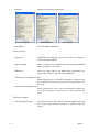
・Property
Camera Properties
・Exit GXLink
Displays item property information.
MCFF Properties
AVI Properties
Ends the GXLink application.
○Camera Items
・Download...
Downloads the image data from the camera and creates a
camera image file (MCFF).
・Auto Download...
After recording ends, downloads the camera image file (MCFF).
Refer to page 3-91 for details.
・USB Save...
Saves the image data to the USB media connected to the
camera and creates a camera image file (MCFF)
・Load Recording Setting from file...
Reads settings such as camera photographic conditions from
the parameter file (prm) and sets the camera selected on the
Item List.
・Save Recording Setting to file...
Saves settings such as the current photographic settings for
the camera selected in the Item List on the parameter file
(prm).
○File Items (MCFF)
・Convert Image Format…
3 - 8
Converts and saves the camera image file (MCFF/CIF) with
the current image quality settings to a specific image file
format.
(00168)
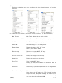
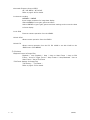
■View Menu
The items on the view menu vary according to the item selected (camera, file) from the
Item List.
View menu
View menu
(for camera item (GX) selection) (for camera item (fx) selection)
View menu
(for file item selection)
・Main Toolbar
Main Toolbar display/ do not display switch.
・Camera Parameter Toolbar
Camera Parameter Toolbar display/ do not display switch.
・Item Toolbar
Item Toolbar display/ do not display switch.
・Status Bar
Status Bar display/ do not display switch.
・Rotate Image
Rotates the camera, MCFF, CIF image.
Refer to page 3-69 for details.
・Reverse Image
Reverses the camera, MCFF, CIF image.
Refer to page 3-70 for details.
・Zoom In / Zoom Out
Displays the enlarged/reduced image.
・Actual size
Displays the actual size of the image.
・Zoom Tool
Zoom Tool ON/OFF switch.
Displays the desired magnification of the image. Refer to
page 3-86 for details.
・Full screen
Automatically adjusts the magnification so the image fills the
entire screen.
・Frame Counter Display
Frame counter display switch. Display types include the
frame display and the relative time (unit: seconds) from the
trigger frame time. During EST recording, the relative time is
not accurate. Additionally, errors in the relative time display
may occur when the time stamp is ON.
(00168)
3 - 9
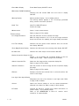
・Event Mark Display
Event Mark Display ON/OFF switch.
・IRIG LOCK, EVENT2 DISPLAY
Switches the GX camera IRIG lock and event 2 display
ON/OFF.
・Warning Display
Warning window display / do not display switch.
The warning window displays a list of warnings generated
during camera use and file operation.
・Hand Tool
Hand Tool ON/OFF switch.
Scrolls the image.
・Measurement
Starts / stops measurements.
Refer to page 3-87 for details.
○Camera Items
・Live Image Resolution...
Sets the reduction of the fx camera live image.
With live image reduction (1/2, 1/4), the live image resolution
drops but the time for updating the image display decreases.
・Live Time Display
Switches the GX camera frame absolute time and current
time display ON/OFF.
・Zoom Magnification Display
Switches the GX camera zoom setting value display ON/OFF.
・All Video ON
Switches the video output for all cameras ON/OFF.
・Display Composite Image On/Off
Display / do not display the composite display of the live
image and file image. Refer to page 3-95 for details.
・Select Composite File...
Select the live image and the composite display file.
Refer to page 3-95 for details.
・Select Fit Direction
Sets the position of the live image and the composite display
file image.
Refer to page 3-95 for details.
・Reticule
Displays horizontal and vertical lines in red and confirms the
center of the image.
・Low Light View Angle Display
Designates the color of the frames in Low Light mode. Refer
to page 3-40 for details.
3 - 10
・Control
Opens the Control window to set the camera parameters
selected in the Item List. Refer to page 3-29 for details.
・I.I.Toolbar
Controls the RX-6 I.I. camera and verifies information. I.I.
toolbar display / do not display switch.
Refer to the MEMRECAM fx RX-6 I.I. camera user's
manual for I.I. toolbar details.
(00168)
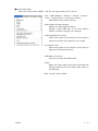
■Control Menu
If there are no items on the Item List, the control menu is not displayed.
The items on the control menu vary according to the item selected.
Control menu
(camera item selection)
Control menu
(file item selection)
○Camera Item
・Camera Control
VIEW / ARM / Trigger / Playback / Loop Playback / Stop / Jump to Start
Frame / Jump to End Frame / Jump to Trigger Frame / Step Forward / Step
Backward / Set as Start Frame / Set as End Frame
・Syncing
Synchronizes camera time when the fx camera has an M-HUB connection.
Used with an IRIG connection or after the synchronization settings fail during
a camera connection.
Refer to page 3-102 for details of the camera time.
Refer to page 4-3 for details on synchronization setting failures.
・Disconnect Disconnects communication with all cameras.
・Detail Setting...
Displays the Detailed Settings dialog box with single camera control.
Refer to page 3-39 for details.
Opens "The list of camera setup" window with multiple camera control.
Refer to page 3-29 for details.
・Memory Segment Operation
Memory Segment / Segment Scan / Hide Segment / Segment Scan of all
cameras / Hide Segment of all cameras Refer to page 3-40 for details.
(00168)
3 - 11
・Automatic Exposure Control (AEC)
AE / AE AREA / AE CYCLE
Refer to page 3-43 for details.
・Luminance encoding
NORMAL / LINEAR
Input/output properties for image data display.
Select NORMAL to use gain, gamma and knee.
Select LINEAR to ignore gain, gamma and knee settings, and convert the data
to linear display.
・Lock JPad
Prevents camera operation from the JPAD3.
・Unlock JPad
Allows camera operation from the JPAD3.
・Unlock PC
Allows camera operation from the PC. PC LOCK is set with LOCK on the
JPAD3 menu (SYS MENU).
○ File Items
・Playback Control of Image Files
Playback / Loop Playback / Stop / Jump to Start Frame / Jump to End
Frame / Jump to Trigger Frame / Step Forward / Step Backward / Set as
Start Frame / Set as End Frame
・T=0 Frame Settings for Image Files
T=0 Setting… / T=0 Reset…
Refer to page 3-79 for details.
3 - 12
(00168)
■Image Quality Menu
When the selected item is MCFF / CIF file, the image quality menu is shown.
・Gain / White Balance / Enhance / Gamma / Chroma /
Knee / Low Pass Filter / Luminance encoding
Select MCFF image quality settings.
・White Balance Display/Settings
Displays the white balance window.
Displays current RGB Gain in the white balance
window, and allows changes in the settings.
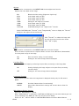
・Adjust Brightness/Contrast...
Shows a bar graph of the luminance of the image to
adjust the contrast and brightness of the image.
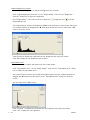
・Input Black Level...
Shows a bar graph of the luminance of the image to
adjust the input data black level.
・RGB Matrix Correction
Corrects the image data RGB matrix.
・Reset
Makes the image quality adjustment performed with
GXLink invalid and sets the image quality saved on
the MCFF file.
Refer to page 3-59 for details.
(00168)
3 - 13
■AVI Settings Menu
When the selected item is MCFF / CIF file, the AVI settings menu is shown.
・Cutout
Select to cut the image to 640×480.
・Resize
Select to reduce the image cut by ½.
・FontSize
Select the font size for the superimposed information.
(Small, Middle, Large)
・Superimpose
Select to superimpose information on the converted
image. (None, Frame no. , All)
・Frame Display
Select the style for the superimposed frame
information.
(Frame Number, Relative Time, Absolute Time)
・Comment Display
Select the recording comments superimposed on
the converted image.
・IRIG Lock,Event2 Display
Switches the IRIG lock for the GX camera and the
event 2 display ON/OFF.
・ Superimpose Image / Select File of Superimposed
Image... / Superimpose Image Size / Superimpose Image
Position
Specifies the desired image file superimposed.
Refer to page 3-66 for details.
■Sync Display Menu
If there are no items in the item list, the Sync Display menu is not shown.
・Select All
・Clear All
・Sync Display...
Specifies all items in the item list for synchronized display.
Deletes all items in the item list for synchronized display.
Switches to synchronized display / selection item display.
Refer to page 3-77 for details.
3 - 14
(00168)
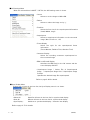
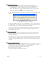
■Settings Menu
・Camera Registration
・Option…
Camera Registration is required for fx camera connection.
Refer to page 3-4 for details.
Sets various GXLink settings. Refer to page 3-96 for details.
(1)Default Folder
(2)Auto Conversion Settings
Default folder settings
Automatically applies image quality settings and parameters
for conversion settings
(3)Conversion Settings
Format conversion algorithm settings
(4)Default Conversion
Sets file type and compression during format conversion
(5)GUI Setup
Switches to/from Basic Mode and Expert Mode
Switches to/from individual conversion and batch conversion
(List)
(6)Frame Time
Frame absolute time display settings
(7)Log Save
Camera communication log save time settings
(8)ConnectType
Selects connection method for fx cameras
(TCP/IP, FC-AL, Gbit)
(9) Synchronous Setting
Settings enabling use of IRIG and EST signals
(10)GX I/O Signal Setting
Settings related to the GX camera input/output signals
(11)Exposure Timing Setting Settings to coordinate exposure times with other models
(12)GX Video Disp
Sets items shown on the GX camera video display
(13)Warning Display ON/OFF Setting
Turns ON/OFF warnings for frame rate, IRQ, remaining
battery, RTC low battery
(14)Auto Sequence
Sets camera automatic control
(15)Live image
Selects camera live image
Caution
Of the option settings listed above, set (3) (6) (9) (10) and (11) before
connecting cameras and opening MCFF files.
Even if settings are changed with the camera/file open, they won't be applied
until the next camera / file is opened.
■Help menu
・About GXLink
(00168)
Display GXLink Application version information
3 - 15
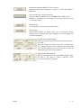
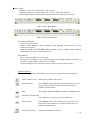
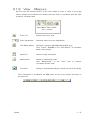
3.5 Toolbar
■Item Toolbar(Basic Mode/Expert Mode)
[Item Toolbar:Basic Mode]
[Item Toolbar:Expert Mode]
Add Items
Open Image File
Opens the image file and adds to the item list as file items.
Attach the camera
Starts communication with the camera and adds the camera item to the
item list.
Item List
Displays items (camera connections, image files open).
Sync Display check box
Item mark
If a camera, shows the nickname for the camera.
If a file, shows the image file base name.
If a camera, shows the camera type or memory segment. Memory segments
are shown as MEM.
If a file, shows the image file type (mcf, cif, avi, tif, bmp, jpg).
Camera head number (shown only with the multi camera DRP)
Camera status
If a camera, disconnects all cameras and deletes all camera items from the
item list. If a file, closes the file displayed and deletes the file item from the
item list.
Closes all items and deletes them from the item list.
3 - 16
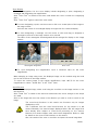
(00168)
・Download image data (MCFF) from the camera
Download image data recorded on a camera to a PC and creates a
MCFF file.
・Converts format of camera image file
Converts and saves MCFF files in AVI/BMP/TIFF/JPEG format.
If MCFF is designated as the format for conversion, the time is cut
out and then saved.
・All Video ON
Turns ON/OFF all of the camera video output.
・Sync Display
Synchronizes display for items where the synchronized display
setting box is checked. Click Sync Display to execute/delete the
synchronized display.
・Camera Control (Basic Mode)
Sets Frame Rate・Frame Size・Shutter Speed (Shutter)・
Low Light.
Sets the priority for either frame rate or frame size.
For example, if frame rate is selected, the frame rate
can be freely selected but the frame size is limited to
values within the frame rate conditions.
・Image Quality (Expert Mode)
Sets Chroma・Brightness・Contrast・White Balance. Also,
the light to the right of "Option" indicates "Auto
Conversion Settings" is applied.
(00168)
3 - 17
・Detailed Camera Settings (Basic Mode)
Displays the "Detailed Settings" dialog box for single camera control.
Detailed Settings
Open the "List of Camera Setup" window for multiple camera control.
Refer to page 3-29 for details.
The List of Camera Setup Window
・Superimpose information settings for format conversion (Basic Mode)
Turns all superimpose settings ON/OFF.
Refer to page 3-66 for details.
・T=0 Setting (Expert Mode)
T=0 frame settings for image files.
(MCFF/CIF/AVI/TIFF/BMP/JPEG/NWF)
Refer to page 3-79 for details.
・Auto Download Settings (Expert Mode)
Auto Download function (automatically downloads images after camera
recording has been completed) settings (save file name, save range designation).
Refer to page 3-91 for details.
3 - 18
(00168)
■Right Click Item Menu
Select and right click an item on the item list to display the menu.
Camera Item Menu
Close
Disconnects all connected cameras and
deletes all camera items from the item list.
Attach/Detach
Connects/disconnects
cameras.
Control
all
connected
Displays camera control window.
Refer to page 3-29 for details.
Segment Scan…
Performs segment scans.
When a segment scan is performed, images
for other segments saved on the camera
are added to the item list as MEM items.
Detail Settings...
Shows the Detailed Settings dialog box.
Refer to page 3-39 for details.
(00168)
Download...
Downloads image data from the camera and
creates camera image files (MCFF).
USB Save...
Saves image data on the USB media
connected to the camera and creates
camera image files (MCFF).
AE
Selects the settings for automatic exposure
control (AEC).
Refer to page 3-43 for details.
Property...
Displays the camera properties.
Refer to page 3-8 for details.
I.I.Property...
Displays the RX-6 I.I. camera properties.
I.I. properties are shown only when a RX-6
I.I. camera is connected.
3 - 19
MCFF/CIF File Item Menu
Close
Closes MCFF/CIF files and deletes items
from the item list.
Convert Image Format
Converts formats.
Refer to page 3-72 for details.
Property...
Display MCFF/CIF properties.
Refer to page 3-8 for details.
AVI/TIFF/BMP/JPEG File Item Menu
3 - 20
Close
Closes AVI/TIFF/BMP/JPEG files and
deletes items from the item list.
Property...
Displays AVI/TIFF/BMP/JPEG file
properties.
Refer to page 3-8 for details.
(00168)
■Main Toolbar
Playback tool for items selected from the item list.
Camera recording and display image zoom / scroll / full screen functions.
Expert Mode includes a measurement function and cutout setting of conversion.
[Main Toolbar:Basic Mode]
[Main Toolbar:Expert Mode]
Recording and Playback
・ Camera recording control
・ Camera image playback control (playback range, playback speed, frame by frame,
forward and reverse)
・ Image file (MCFF/AVI/TIFF/BMP/JPEG) playback control (playback range, playback
speed, frame by frame, forward and reverse)
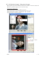
View・Measure
・ Zoom, scroll and display all of the image
・ Display the coordinates for the noteworthy points of the image displayed (can be set to
the point of origin). Refer to page 3-85 for details.
・ Capture settings for the conversion settings. Refer to page 3-68 for details.
Operation Buttons
Use the mouse to click on these buttons to control and operate the camera and files.
Jump to Start Frame
Displays the playback start frame.
Step Backward
In the READY mode, goes back one frame. Press for a long
time to go back quickly. In the PLAY/LOOP mode, the
playback rate decreases.
Stop
Stops PLAY, VIEW and ARM and switches to READY mode.
Playback/Loop Playback
Press Playback for a long time for loop playback.
(00168)
Step Forward
In the READY mode, goes forward one frame. Press for a
long time to fast forward. In the PLAY/LOOP mode, the
playback rate decreases.
Jump to End Frame
Displays the playback end frame.
3 - 21
VIEW/ARM
In the READY mode, switches to the VIEW mode.
In the VIEW mode, switches to the ARM mode (recording).
Trigger
In the ARM mode, enables the manual trigger (ends recording).
In the READY mode, displays the trigger frame / event frame.
Set as Start Frame
Sets the current frame to the playback start frame.
Set as End Frame
Sets the current frame to the playback end frame.
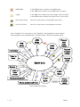
Press "Playback" for a long time or click "Playback" during playback for loop playback.
During playback, click Step Backward or Step Forward to change the playback speed.
REC
Mode
Fast forward
ARM
Mode
VIEW
Mode
Playback
start
frame
settings
Playback
end frame
settings
Press
long time
Frame by
frame
Playback
speed
Press
long time
READY Mode
Reverse
Press
long time
Frame by
frame
reverse
LOOP
Mode
PLAY
Mode
Display playback start
Display playback end frame
Change
playback
speed
Camera Operation Diagram
3 - 22
(00168)
■Camera Parameter Toolbar (only for Expert Mode)
Sets parameters for camera recording/playback control.
Parameter values shown are the camera values selected with the item toolbar.
If parameters are set with the camera parameter toolbar, the parameters for all cameras are
set.
■Status Bar
If there is a cursor on the toolbar, detailed information for that
button / display is shown.
If there is a cursor on the image monitor, the location of the cursor
is shown.
If there is a cursor on the image monitor, the RGB value for the image
at that location is shown.
■I.I.TOOLBAR
Controls the RX-6 I.I. camera and verifies information.
This I.I. toolbar is displayed and used only for a RX-6 I.I. camera connection.
Refer to the MEMRECAM fx RX-6 I.I. camera user's manual for I.I. toolbar details.
(00168)
3 - 23
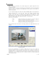
3.6 Recording・Playback
■Recording
While in the READY mode, click
VIEW/ARM on the main toolbar and the camera will
switch from WAIT→VIEW, and the live image photographed by the camera is displayed on the
image monitor. The image displayed on the image monitor is the same as the image displayed
on the video monitor. While in the VIEW mode, the photographic parameters can be set.
VIEW/ARM again to start recording. The camera will
After verifying the settings click
access the ARM mode, and writing to the camera image memory will begin, and it will enter
the awaiting trigger state.
Upon receiving trigger signal input, recording ends and it enters the READY mode. (NORMAL
recording) (Click
the trigger on the Main Toolbar to manually output trigger signals)
With multiple cameras,
the trigger button on the main toolbar is operational when all
cameras are in the ARM mode. The trigger button is not operational for recording with
BURST settings.
The Rec Trigger Modes include (1) NORMAL recording, (2) event recording, (3) burst
recording and (4) multi trigger recording.
These four Rec Trigger Modes cannot be used together. Only one Rec Trigger Mode can be
selected. Priorities in the Rec Trigger Mode are set as multi trigger recording > burst
recording > event recording > NORMAL recording.
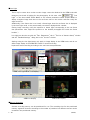
(1) NORMAL Recording
NORMAL recording is a recording method where trigger signals can only be received once
during segment recording.
GX camera NORMAL recording includes NORMAL / NORMAL (A) / NORMAL (L).
In NORMAL, once the current segment recording has been completed, it switches to
READY.
NORMAL(A) refers to the AUTO mode where recording ends at trigger signal input for
the number of segments.
NORMAL(L) refers to the LOOP mode where the segment is switched and repeatedly
recorded until the stop button is clicked.
※AUTO Mode and LOOP Mode
AUTO mode and LOOP mode refers to the mode where the automatic segment switch
and ARM set by the GX camera is repeated. fx cameras do not have this function.
Cameras in the AUTO mode automatically switch the segments to ARM when recording
has been completed.
The conditions for ending automatic segment switching and ARM start include when the
current segment is the final segment (if the memory is split into 4 sections, when the
current segment is 4th) and when there is an ARM failure due to a memory protect
function.
In the AUTO mode, if the switched segment recording has been completed, recording of
that segment cannot be performed. (memory protect function)
In this case, since ARM fails, a warning is displayed, and the FAULT signal from the
camera is turned ON. Click the stop button to delete the warning and the FAULT signal.
3 - 24
(00168)
In the LOOP mode, the camera automatically switches the next segment to ARM after
camera recording has been completed. This differs from the AUTO mode, and it accesses
ARM even when the switched segments have completed recording.
Click the stop button for the ending conditions for automatic segment switching ARM
start.
(2)Event Recording
When there is multiple input of external trigger signals during recording, the first external
trigger signal is treated as the original trigger signal and the subsequent external trigger
signals are recorded as generated events.
Perform any of the following operations for event recording.
・Set Rec Trigger Mode in the Detailed Settings dialog box to EVENT.
・Set Rec Trigger Mode in the Rec. Parameters tab of the camera settings window to
EVENT.
GX camera event recordings include EVENT/ EVENT (A) / EVENT(L).
An EVENT is a recording of only one segment but in AUTO and LOOP modes, when
recording of one segment ends, recording of the next segment begins.
EVENT (A) refers to the AUTO mode that ends recording when recording of all segments
has been completed.
EVENT (L) refers to the LOOP mode where the segments are switched and repeatedly
recorded until the stop button is clicked.
(3)Burst Recording
A recording method for only the period when there is external trigger signal input.
Perform any of the following operations for burst recording.
・Set Rec Trigger Mode in the Detailed Settings dialog box to BURST.
・Set Rec Trigger Mode in the Rec. Parameters tab of the camera settings window to
BURST.
GX camera burst recordings include BURST/BURST(A)/BURST(L).
A BURST is a recording of only one segment but in AUTO and LOOP modes, when
recording of one segment ends, recording of the next segment begins.
BURST(A) refers to the AUTO mode that ends recording when recording of all segments
has been completed.
BURST(L) refers to the LOOP mode where the segments are switched and repeatedly
recorded until the stop button is clicked.
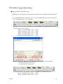
(4)Multi Trigger Recording
Partitions the selected memory segments into 2 - 16 blocks, and automatically switches
blocks for each trigger signal input for recording.
There is an All Blocks mode (MULTI(A)) that ends recording with trigger signal input for
the number of blocks and a Continuous mode (MULTI(C)) that repeatedly records until
the stop button is clicked. The GX camera has an AUTO mode and a LOOP mode that
moves segments using trigger input for the number of blocks in the All Blocks mode.
Perform any of the following operations for multi trigger recording.
・Set Rec Trigger Mode in the Detailed Settings dialog box to MULTI and
simultaneously designate the number of blocks partitioned.
・Set Rec Trigger Mode in the Rec. Parameters tab of the camera settings window to
MULTI and simultaneously designate the number of blocks partitioned.
GX multi trigger recordings include MULTI(A)/MULTI(C)/MULTIS(A)/MULTIS(L).
MULTI(A) refers to the All Blocks mode that ends recording with trigger signal input for
the number of blocks.
(00168)
3 - 25
MULTI(C) refers to the Continuous mode that performs repeated recording until the stop
button is clicked.
MULTIS(A) refers to the AUTO mode that ends recording with trigger signal input for the
number of segments.
MULTIS(L) refers to the LOOP mode where the segments are switched and repeatedly
recorded until the stop button is clicked.
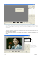
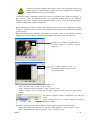
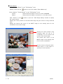
■ Camera Playback (Verify Image)
Once recording has been completed and the camera status is READY, the recorded images
can be played back.
The playback range can be designated by operating the playback slider.
Playback
Current frame
Top frame
Starting frame of
playback range
T=0 frame
(trigger frame)
End frame of
playback range
End frame
[Playback Slider]
The playback parameters can be set with the "Detailed Settings" dialog box. Additionally,
precise settings for the playback range can be made in single frame units.
If there are multiple cameras connected, the playback parameters can be set in the window
showing "The List of Camera Setup". Parameters for all of the cameras can be set in the
collective row.
Designate the playback range to enable forward playback, reverse playback and loop playback
and verify the playback images. Then, verify the data download range.
Detailed image verification is possible by showing the frame for the recorded image.
Use the zoom scroll tool described later for zoom display and scrolling of the still images
shown.
The zoom and scroll state set for still images is valid for each playback state (forward, reverse,
loop playback).
Zoom and scroll are functions of the image display and are unrelated to downloading.
When downloading, the recorded image is saved with no correlation between zoom and scroll
display.
The following playback speeds can be set for the GX camera operation.
・Playback Rate (NTSC) -1920,-960,-480,-240,-120,-60,-30,-15,-10,-5,-2,-1,
1,2,5,10,15,30,60,120,240,480,960,1920 Unit:pps
・Playback Rate (PAL) -2000,-1000,-800,-400,-200,-100,-50,-25,-10,-5,-2,-1,
1,2,5,10,25,50,100,200,400,800,1000,2000 Unit:pps
・The >>>>>> in the "Playback Rate" combo box is the actual playback speed.
Plays back at the same rate as the recording frame rate.
・ ->->-> and <-<-<- in the "Playback Rate" combo box during synchronized display
->->-> is the fastest playback speed that does not drop frames of live
camera images, and performs forward playback.
<-<-<- is the fastest playback speed that does not drop frames of live
camera images, and performs reverse playback.
3 - 26
(00168)
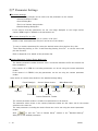
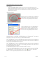
■Playback Slider
Use to designate playback frame and set playback range.
Playback slider
The playback slider refers to different displays than Rec Trigger Mode.
(1)
Example of Event Frame Display
Frames input by the subsequent trigger signals are treated as event frames.
T=0 frame
(trigger frame)
(2)
Event
frame
Event
frame
Example of BURST Recording Display
Records the time frame during which the burst signals are input to the trigger connector.
Burst
block 1
(3)
Burst
block 2
Burst
block 3
Burst
block 4
Example of Multi Trigger Frame Display
Records the number of partitioned blocks.
Block 1 T=0 frame
(Block 1 trigger frame)
Block 1
(00168)
Block 2 T=0 frame
(Block 2 trigger frame)
Block 2
Block 3 T=0 frame
(Block 3 trigger frame)
Block 3
3 - 27
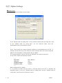
3.7 Parameter Settings
■Parameter Settings
Any of the following methods can be used to set the parameters on the camera.
・Camera Parameter Toolbar
・Control Dialog Box
・The List of Camera Setup window
・Detailed Settings Dialog Box
If the camera recording parameters are set, the image displayed on the image monitor
(camera VIEW image) is updated to the parameters set.
■Parameter Setting File (prm file)
Parameters set for the camera can be saved in a file (prm).
Details of the saved parameter file (prm) can be set on the camera.
To save or read the parameter file, select the desired camera from the Item List, click
"Save Recording Setting to File.../Load Recording Setting from File" on the file menu and
pick the file name.
Refer to Appendix C for details of the parameter file.
■Camera Parameter Toolbar (Expert Mode only)
The Camera parameter toolbar functions once a connection between the PC and camera has
been established.
If the camera is in VIEW, the recording parameters can be set using the camera parameter
toolbar.
If the camera is in READY, the play parameters can be set using the camera parameter
toolbar.
Open the list of camera setup window or the detailed settings dialog
Frame Rate(pps)
Segment
Custom Shutter button
Trigger
Frame Size
White Balance(K)
Low Light
Shutter
Camera Parameter Toolbar
Chroma
Gain
The camera parameter toolbar is a GUI to set parameters on all cameras.
The parameter values shown on the camera parameter toolbar are the values set for the camera
selected on the item list.
The main parameters, including the camera frame rate can be set using the camera parameter
toolbar.
Click
to open the "List of Camera Setup" window or the "Detailed Settings"
dialog box to set detailed parameters.
3 - 28
(00168)
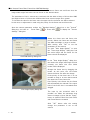
■Control Window
Select a camera on the item list and click "Control" on the right menu
of the mouse to open the "Control" window.
Items that can be set include, from the top, current segment, frame rate
(pps), frame size, rec trigger mode, trigger timing, shutter, low light,
white balance, chroma, gain, AE, DRES mode, pixel bit depth and RGB
matrix correction.
Click "Previous" to move to the camera settings higher on the item
list.
Click "Next" to move to the camera settings lower on the item list.
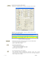
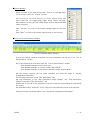
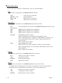
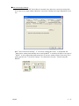
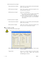
■"The List of Camera Setup" Window
"The List of Camera Setup" Window
If there are multiple cameras connected, all of the parameters can be set in the "List of
Camera Setup" window.
Any of the following can be used to open the "List of Camera Setup" window.
・Click Detailed Settings on the control menu.
・Click Detailed Settings on the item toolbar. (Basic Mode)
・Click Detailed Settings on the camera parameter toolbar. (Expert Mode)
Set the memory segment, the live image resolution and rotate the image in "Camera
Configuration Information".
Set recording parameters in the "Rec. Parameters" tab.
Set play parameters in the "Play Parameters (Image Quality)" tab, "Play Parameters
(Range)" tab and the "Play Parameters" tab.
Double click on the cell for the parameter to be set to open the setting dialog box and change
the setting.
Set parameters using "Collective" at the very top to set parameters for all of the cameras.
Verify the camera connection status using "Connection Configuration Information".
(00168)
3 - 29
・Camera Configuration Information
Camera Configuration Information (GX camera connection)1
Camera Configuration Information(GX camera connection)2
"Camera Configuration Information" Items
(ID, Memory Segment, Live Image Resolution, Rotate Image, Reverse Image, Black Balance
Update, Zoom, Scroll Position, Auto View, PC Lock and Lock JPad can be set. Other items
are for display only and the settings cannot be changed.)
ID
TYPE
Nickname
FC-AL node
IP Address
MAC Address
CID
DRP Version
Memory
Master/Slave
Memory Segment
Live Image Resolution
Rotate Image
Reverse Image
BATT.STATUS
Video Out
Auto View
Video Out
Auto View
PC Lock
Lock JPad
Save Range Mode
Black Balance Update
Camera Time
Zoom
X Scroll Position
Y Scroll Position
Trigger Filter
EST Filter
3 - 30
Camera (DRP) ID
Camera (DRP) type
Camera (DRP) nickname (refer to page 3-4)
Camera (DRP) fiber channel node name (shown with FC-AL connection)
Camera (DRP) IP Address (shown with TCP/IP connection)
Camera (DRP) MAC Address (shown with TCP/IP connection)
Camera (DRP) identification number
Camera (DRP) firmware version
Maximum recording memory
If multiple camera heads, the memory used for each camera head.
Camera synchronization master, synchronization slave settings
Memory for one segment, and number of segments
Live image resolution
Image rotation angle
Image reverse direction
Battery status
Video output method (NTSC/PAL)
Auto View setting
Video output method (NTSC/PAL)
Auto View setting
Operation locks status from PC
Operation lock status from remote control
Setting whether or not to continue save range
Black Balance calculation
Camera time setting
Video display zoom setting
Video display X scroll setting
Video display Y scroll setting
External trigger signal noise filter
External synchronization signal noise filter
(00168)
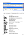
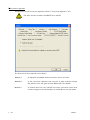
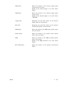
・Rec. Parameters
Rec. Parameters (GX Camera) 1
Rec. Parameters (GX Camera) 2
Rec. Parameters (GX Camera) 3
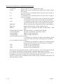
"Rec. Parameters" Items
ID
Camera (DRP) ID
TYPE
Camera (DRP) type (For display only. Setting cannot be changed. )
Nickname
Camera (DRP) nickname (refer to page 3-4)
(For display only. Setting cannot be changed. )
Status
Camera (DRP) status (For display only. Setting cannot be changed. )
Seg
Recording segment number (1~128)
Scene No.
Photograph number (0~65535) +1 for each photograph
Frame Rate
Recording frame rate (pps) (values that can be set vary by model)
Frame Size
Recording frame size
(values that can be set vary by model)
Blocks
Select 1~16 values for the number of blocks for partition recording
Rec Trigger Mode Sets Rec Trigger Mode
NORMAL
Normal recording
NORMAL(A)
Automatically switches segments and records
NORMAL(L)
Repeated recording until "Stop" is pressed
EVENT
Saves external trigger signals when recording
EVENT(A)
Automatically switches segments and records
EVENT(L)
Repeated recording until "Stop" is pressed
BURST
Records only with external trigger signal input
BURST(A)
Automatically switches segments and records
BURST(L)
Repeated recording until "Stop" is pressed
MULTI(A)
Records the number of blocks
MULTI(C)
Repeated recording until "Stop" is pressed
MULTIS(A)
Automatically switches segments and records the number of
blocks
MULTIS(L)
Automatically switches segments and records and repeatedly
records until Stop is pressed
Trigger Timing
Recording Trigger Position
START
Sets the START trigger position.
CENTER
Sets the CENTER trigger position.
END
Sets the END trigger position.
BURST
Sets the BURST recording. Do not select BURST if there are
two or more blocks.
CUSTOM
Sets the CUSTOM trigger position.
(00168)
3 - 31
Shutter
2k
5k
5k
10k
20k
50k
100k
200k
CUSTOM
Low Light
OFF
100pps
250pps
500pps
1000pps
Shutter Speed (values that can be set vary by model)
Record at 2k shutter speed.
Record at 5k shutter speed.
Record at 5k shutter speed.
Record at 10k shutter speed.
Record at 20k shutter speed.
Record at 50k shutter speed.
Record at 100k shutter speed.
Record at 200k shutter speed.
Record at a speed with a CUSTOM setting.
Setting where the Low Light mode preview brightness corresponds to
the frame rate.
Low Light mode is turned OFF.
Live image displayed corresponding to a frame rate of 100pps.
Live image displayed corresponding to a frame rate of 250pps.
Live image displayed corresponding to a frame rate of 500pps.
Live image displayed corresponding to a frame rate of 1000pps.
AE
Select automatic exposure function. Sets fx-K5 and GX cameras.
OFF
No automatic exposure.
LOW
Low average image brightness.
NORMAL
Normal average image brightness.
HIGH
High average image brightness.
AE AREA
Select automatic exposure range. Sets fx-K5 and GX cameras.
FULL
Detects brightness in the entire range.
CENTER
Detects brightness in the center of the image.
UPPER
Detects brightness in the upper part of the image.
LOWER
Detects brightness in the bottom part of the image.
LEFT
Detects brightness in the left part of the image.
RIGHT
Detects brightness in the right part of the image.
AE CYCLE
Designate the automatic exposure cycle. Sets fx-K5 cameras.
Gain
Brightness
LOW
Lower gain by one aperture.
NORMAL / 0dB
Normal brightness.
HIGH / 6dB
Raise gain by one aperture.
12 dB
Raise gain by two apertures.
Gamma
Gamma correction
OFF
No gamma correction.
LOW
Low gamma correction.
NORMAL
Normal gamma correction.
White Balance
White Balance
AUTO
Auto White Balance setting.
3100K
3100K setting for lighting color temperature.
5000K
5000K setting for lighting color temperature.
9000K
9000K setting for lighting color temperature.
REG
Uses the auto white balance setting obtained with SET during
the preview.
3 - 32
(00168)
Enhance
OFF
LOW
NORMAL
HIGH
Knee
Chroma
0%
50%
100%
150%
200%
Comment
Rec possible Frame
Enhance profile
No enhance.
Low enhance.
Normal enhance.
High enhance.
Turns correction expanding the dynamic range ON/OFF by lowering the
gain of the signals exceeding a specific brightness level.
Color depth (chroma)
Sets chroma to 0%. Black and white image.
Sets chroma to 50%.
Sets chroma to 100%. Standard chroma.
Sets chroma to 150%.
Sets chroma to 200%.
Recording comments. Input setting up to 30 ASCII characters.
Number of frames that can be recorded.
(For display only. Setting cannot be changed.)
DRES Mode
Dynamic range expansion shutter mode. GX camera setting.
OFF
Normal setting.
Sets dynamic range to approximately 200%.
LOW
Sets dynamic range to approximately 400%.
MID
Sets dynamic range to approximately 800%.
HIGH
Sets dynamic range to approximately 1600%.
Exposure Timing
Used to match fx, ci camera exposure times.
(For display only. Setting cannot be changed.
To change, set with "Exposure Time Settings" in the option menu.
Refer to page 3-106 for details.)
Pixel Bit Depth
Pixel Bit Depth setting
8bit
Sets the bit length to 8bit.
10bit
Sets the bit length to 10bit.
12bit
Sets the bit length to 12bit.
Black Balance
Black Balance ON/OFF setting. GX camera setting.
Rec Sync Signal
EST selection (For display only. Setting cannot be changed.)
To change, with "Syncing" in the option menu. Refer to page 3-102 for details.)
Exposure phase
Designate the exposure phase shift with a value 0~359 (°).
GX camera setting.
RGB Matrix
Turns RGM matrix correction ON/OFF for the image data.
GX camera setting.
Luminance encoding
Input/output properties when image data is displayed.
GX camera setting.
NORMAL
Use Gain・Gamma・Knee
LINEAR
Convert to linear data for display.
(00168)
3 - 33
・Play Parameters
Play Parameters1
Play Parameters2
"Play Parameters" Items
(ID, Frame No., Comment, Play Start, Play End settings.
Other items are for display only. The setting cannot be changed. )
ID
TYPE
Nickname
Status
Frame No.
Seg
Scene No.
Frame Rate
Frame Size
Blocks
Rec Trigger Mode
Shutter
AE
AE AREA
AE CYCLE
Comment
DRES Mode
Exposure Timing
Pixel Bit Depth
Black Balance
Rec Sync Signal
Exposure phase
3 - 34
Camera (DRP) ID
Camera (DRP) type
Camera (DRP) nickname (refer to page 3-4)
Camera status
Current frame
Segment number
Scene number
Recording frame rate
Recording frame size
Number of blocks for recording
Rec Trigger Mode setting
Shutter speed
Automatic exposure setting
Automatic exposure range
Automatic exposure cycle
Recording comments. Input setting up to 30 ASCII characters.
Dynamic range expansion shutter mode.
Exposure Timing Setting
Pixel bit length setting
Black Balance ON/OFF
EST setting
Exposure phase shift setting
(00168)
・Play Parameters(Image Quality)
Play Parameters (Image Quality)
Play Parameters (Image Quality) Items
ID
TYPE
Camera (DRP) ID
Camera (DRP) type
(For display only. The setting cannot be changed. )
Nickname
Camera (DRP) nickname (refer to page 3-4)
(For display only. The setting cannot be changed. )
Status
Camera (DRP) status
(For display only. The setting cannot be changed. )
Frame No.
Current frame
Gain
Brightness
LOW
Lower gain by one aperture.
NORMAL / 0dB
Normal brightness.
HIGH / 6dB
Raise gain by one aperture.
12 dB
Raise gain by two apertures.
Gamma
Gamma correction
OFF
No gamma correction.
LOW
Low gamma correction.
NORMAL
Normal gamma correction.
White Balance
White Balance
AUTO
Auto White Balance setting.
3100K
3100K setting for lighting color temperature.
5000K
5000K setting for lighting color temperature.
9000K
9000K setting for lighting color temperature.
REG
Uses the auto white balance setting obtained with SET during
the preview.
Enhance
Enhance profile
OFF
No enhance.
LOW
Low enhance.
NORMAL
Normal enhance.
HIGH
High enhance.
Knee
Turns correction expanding the dynamic range ON/OFF by lowering the
gain of the signals exceeding a specific brightness level.
Chroma
Color depth (chroma)
0%
Sets chroma to 0%. Black and white image.
50%
Sets chroma to 50%.
100%
Sets chroma to 100%. Standard chroma.
150%
Sets chroma to 150%.
200%
Sets chroma to 200%.
RGB Matrix
Turns RGB matrix correction for image data ON/OFF.
GX camera setting.
Luminance encoding
Input/output properties when image data is displayed.
GX camera setting.
NORMAL
Use Gain・Gamma・Knee.
LINEAR
Convert to linear data for display.
(00168)
3 - 35
・Play Parameters (Range)
Play Parameters (Range)
Play Parameters (Range) Items
(ID, Play Start, Play End settings. The other items are for display only.)
ID
TYPE
Nickname
Status
Trigger Timing
Trigger Time
Play Start, Play End
Rec. Start, Rec. End
Save Status
3 - 36
Camera (DRP) ID
Camera (DRP) type
Camera (DRP) nickname (refer to page 3-4)
Camera status
Trigger setting
Trigger signal input time
Playback start frame/time, playback end frame/time
Recording start frame/time, recording end frame/time
Save status for camera data
(00168)
・Connection Configuration Information
Connection Configuration Information (M-Hub)
Connection Configuration Information Items (only the ID can be set. The other items are for
display only. )
ID
TYPE
Nickname
Sync
IRIG
I-M SYNC
M S/N
M Port No.
M Port ID
M-S Connect
M-S Sync
S S/N
S Port No.
S Port ID
S-C Connect
S-C Sync
CID
(00168)
Camera (DRP) ID
Camera (DRP) type
Camera (DRP) nickname (refer to page 3-4)
Synchronization setting end status
IRIG signal status
IRIG and master M-Hub synchronization status
Master M-Hub serial number
Master M-Hub port number
Master M-Hub port ID
Master M-Hub and slave M-Hub connection status
(C:connected, D:disconnected)
Master M-Hub and slave M-Hub synchronization status
Slave M-Hub serial number
Slave M-Hub port number
Slave M-Hub port ID
Slave M-Hub and camera connection status
(C:connected, D:disconnected)
Slave M-Hub and camera synchronization status
Camera (DRP) identification number
3 - 37
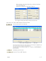
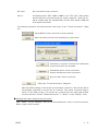
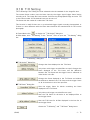
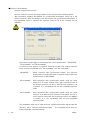
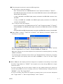
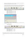
【Example】 Changing the Frame Rate in the "Collective" Row
Double click on the Frame Rate cell in the
"Collective" row.
The "Frame Rate, Frame Size Settings" dialog for
setting parameters will be displayed.
1.
Select the priority for the frame rate and frame size.
If frame rate has priority, the frame rates for all of
the cameras will be displayed on the pull down menu.
Select from the frame sizes shown, which are the
frame sizes possible with the frame rate selected at
that time.
2.
Specify the frame rate to be set.
Once specified, the parameters for all of the cameras
will be set.
Click OK to close the "Frame Rate, Frame Size
Settings" dialog box.
Click Cancel to close the dialog box and return all of
the cameras to the state before the settings were
changed.
【Example】Select a Camera and Set the Frame Rate
1.
Double click on the "Frame Rate" cell to select a
camera.
The "Frame Rate, Frame Size Settings" dialog box
for setting parameters will be displayed.
Select the priority for the frame rate and frame size.
2.
Specify the frame rate to be set.
Once specified, the parameters for only the camera
selected will be set.
Click OK to close the "Frame Rate, Frame Size
Settings" dialog box.
Click Cancel to close the dialog box and return the
selected camera to the state before the settings
were changed.
3 - 38
(00168)
■Detailed Settings Dialog Box
Parameters for a single camera can be set with the "Detailed Settings" dialog box.
Any of the following can be used to open the Detailed Settings dialog box.
・Click "Detailed Settings" on the "Control" menu when one camera is connected.
・Click "Detailed Settings" on the item toolbar when one camera is connected. (Basic
Mode only)
・ Click "Detailed Settings" on the camera parameter toolbar when one camera is
connected. (Expert Mode only)
・Select a camera from the item list and click "Detailed Settings" with the right mouse
button (the "Detailed Settings" dialog box will open when a camera in the item list is designated
even if multiple cameras are connected).
Detailed Settings dialog box
(00168)
3 - 39
■Low Light
There may be cases when a clear monitor image cannot be obtained in the VIEW mode with
"Low
temporary low levels of lighting for the photography. In this case, click
Light" on the item toolbar (Basic Mode) or the camera parameter toolbar (Expert Mode) to
display a brighter image than that on the set frame rate on the monitor and then verify the
angle and focus.
Additionally, if the frame size is too small, a frame larger than the set frame size is displayed
in the Low Light mode, so the area actually recorded is displayed with a border.
(During image recording, verify the aperture to obtain light corresponding to the set frame
rate parameters. Also, adjust the position so the desired photograph fits inside the frame
borders. )
Low Light can also be set with the "Rec. Parameters" tab in "The List of Camera Setup" window
and the "Detailed Settings" dialog box in the "Control" window.
Settings using the low light button only apply to image display in the VIEW mode, and do not
affect image display in the ARM, REC modes or actual recording.
Implement actual recording according to the set frame rate parameters.
Frame
borders
VIEW (Low Light Mode) Live Display
ARM Live Display
VIEW (Low Light Mode) Video Display
ARM Video Display
■Memory Segments
Camera recording memory can be partitioned for use. The recording time for the partitioned
memory segments shortens according to the number of partitions but different scenes can be
recorded in the partitioned memory.
3 - 40
(00168)
Caution
Partitioning memory segments will result in the loss of image data saved in the
camera memory. If essential data remains, be sure to download the image data
before partitioning the memory segments.
To partition memory segments, select the number of partitions with "Memory Segment" in
the "Control" menu. If multiple cameras are connected, double click on the "Memory
Segment" cell in the "Camera Configuration Information" tab in "The List of Camera Setup"
window to change the number of segments.
When segmenting the camera memory and images other than the current segments are saved,
conduct a "Segment Scan" and all of the segments where images are recorded will be added
to the item list.
When switching memory segments and images are already saved in the selected memory
segment, the original memory segment will be added to the item list as a memory item.
Switch from a memory segment with a
recorded image to another memory
segment.
The image selected prior to
switching is added to the item list
as a memory item.
Any of the following can be used for the segment scan.
・ Click "Segment Scan" in the "Control" menu.
・ Click "Segment Scan All Cameras" in the "Control" menu.
・ Select a camera from the item list and click "Segment Scan" with the right mouse
button.
The memory segment number is displayed in the item list
status.
In this example, there is an image recorded in memory
segment number2.
Any of the following can be used to delete memory segment items from the item list.
・Select the camera from the item list and click "Hide Segment" on the "Control" menu.
・Click "Hide Segments from All Cameras" on the "Control" menu.
(00168)
3 - 41
■GX Camera Frame Rate, Frame Size CUSTOM Settings
In addition to the predetermined values for the GX camera frame rate and frame size, the
image width, height and frame rate can be set to the desired values.
The parameters of GX-1 cameras are restricted, with the width a factor of 4 less than 1280,
the height a factor of 16 less than 1024 and the frame rate an integer 50 or greater.
To increase the value for the frame rate, the upper limit for the frame size will be reduced.
In this case, an adjustment is made using the priority for the frame rate and frame size.
Open the camera parameter toolbar, the "Detailed Settings" dialog box or the "Control"
dialog box, and click on
Settings" dialog box.
Frame Rate
or Frame Size
to display the "Custom
Select the frame rate and frame size
priority. Select the frame rate and frame
size width and height, or enter a number.
After setting, click "OK" to set the
parameters to the camera.
Or, click "View Angle Display" to open
the "View Angle Display" dialog box, and
the entire image and the frame for the
frame size will be displayed.
CUSTOM Settings Dialog Box
In the "View Angle Display" dialog box,
the camera live image (still image) and the
currently set frame size area (white
border) will be displayed.
Change the frame size by dragging the
border. At this point, the red border
shows the frame size after the change.
If the priority is the frame rate, it is not
possible to drag to an area that exceeds
the upper limit of the frame size.
If the priority is the frame size, the frame
will automatically be reduced if the upper
limit of the frame size is exceeded when
dragged.
View Angle Display Dialog Box
The input by the numerical value is
possible, too. When the parameter that
wants to change is input, and the "Apply"
button is clicked, Frame Size (red frame)
and Frame Rate are renewed.
Click "OK" button after the setting
change, the parameter is set to the
camera.
3 - 42
(00168)
■AE Control
GX cameras and the fx-K5 camera has an AEC function (automatic exposure). The AEC
function measures light in the specific area of the image to be photographed and changes the
shutter speed so the average brightness of the measured area is a specific value.
While it is possible to set the lens aperture or the shutter settings to match the brightness
for indoor photography, it is difficult to change the settings each time the brightness changes
when outdoors. The AEC function is useful in this type of situation.
Since the constant varies when the shutter speed is changed, it takes several seconds to
focus to the appropriate value when the brightness changes suddenly.
Any of the following can be used to specify AE.
・ Right click the camera item in the item list and select "AE" from the menu.
・ Select the camera in the item list and select "AE" from the "Control" menu.
・ Select "AE" from the "Control" window.
・ Select "AE" from the "Rec. Parameters" in the "Detailed Settings" dialog box.
Select any of the following for AE.
OFF
Do not use AE.
LOW
Adjust to a low level of average brightness.
NORMAL
Adjust to a normal level of average brightness.
HIGH
Adjust to a high level of average brightness.
The upper limit for the AE exposure time is up to the shutter speed set for the recording
parameters. For example, if the shutter speed is set to 5K, the exposure time with AEC
control is up to a maximum of 200[μs].
Additionally, the AE AREA must be designated when using AE.
Any of the following can be used to designate the AE AREA.
・ Select the camera in the item list and select "AE" from the "Control" menu.
・ Select "AE" from the "Detailed Settings" dialog box.
Select any of the following for AE AREA.
FULL
The entire frame is the range.
CENTER
50% of a rectangle (area of 25%) from the center of the frame is the
range.
UPPER
The upper half of the frame is the range.
LOWER
The lower half of the frame is the range.
LEFT
The left half of the frame is the range.
RIGHT
The right half of the frame is the range.
AEC for fx-K5 includes settings determining the cycle that changes the shutter speed (AE
CYCLE). This setting should not be used to frequently change the shutter speed.
The GX does not have this setting.
To designate the AE CYCLE, enter an integer from the "AE CYCLE" in the recording
parameters of the "Detailed Settings" dialog box in millisecond units.
When using AEC, the exposure time for the recorded frames will change for each frame.
Since the GX has a time stamp function, when that function is employed, it is possible to
know the frame exposure time from the information saved for each frame.
The fx-K5 does not have a time stamp function but instead, the final 8 shutter speeds during
recording and their frame range is saved. If the shutter setting is set not to be changed
frequently, it is possible to know the fx-K5 exposure time for each frame.
(00168)
3 - 43
■GX Camera Pixel Bit Depth
The bits per pixel for the photographed image can be changed on the GX camera.
If the number of bits is increased, the depth per pixel increases, resulting in a high quality
image.
If the number of bits is decreased, the depth per pixel decreases, resulting in a lower quality
image but this saves the recording memory and extends the recording time.
Any of the following can be used to change the pixel bit depth.
・ Select "Pixel Bit Depth" in the "Control" window.
・ Select "Pixel Bit Depth" in the "Detailed Settings" dialog box.
Any of the following can be used to select the pixel bit depth.
8bit
Sets the bit length to 8bits. Low image quality.
10bit
Sets the bit length to 10bits. Standard image quality.
12bit
Sets the bit length to 12bits. High image quality.
■GX Camera Exposure Phase
The GX camera can shift the exposure timing (phase) during recording.
However, the exposure phase should be kept at 0 when not conducting exposure phase shift
recording.
To change the exposure phase, designate the value of "Exposure Phase" in the "Detailed
Settings" dialog box in single degree units from 0~359 (°).
Refer to Chapter 5, 5.6 Exposure Phase Shift Recording for details regarding exposure phase
shift recording.
■GX Camera Black Balance
Black Balance is a function that corrects the GX camera sensor pixel dependent noise.
With the GX camera, the sensor temperature properties are calculated and FPN correction is
applied to remove the noise so when conducting high precision photography, applying black
balance immediately before or after photographing is recommended.
Black Balance removes sensor noise with the frame rate and frame size settings so if the
frame rate or frame size is altered when the black balance is ON, a warning encouraging black
balance correction is displayed on the video monitor or the warning window. When using the
black balance function, calculate the black balance using the same frame rate and frame size
settings as those for photographing.
To calculate the black balance, first set the frame rate and frame size to that used for
photographing. Next, place the cap on the camera lens so light does not reach the sensor.
Conduct "Black Balance Update" in "Camera Configuration Information" in the "Detailed
Settings" dialog box.
At this point, the camera status will show one of the following, and the correction data will be
created.
The definitions of the status are shown below.
NONE
Black Balance is not ready.
BUSY
Black Balance is busy.
VALID
Black Balance has been completed.
3 - 44
(00168)
To switch the black balance, select ON/OFF for the Black Balance in the recording
parameters found in the "Detailed Settings" dialog box.
ON
Using black balance corrected data.
OFF
Not using black balance corrected data, correcting internal camera
data.
It is possible to conduct black balance at a later time for images that have already been
recorded.
In this case, to conduct the black balance calculation, select ON for the Black Balance in the
play parameters found in the "Detailed Settings" dialog box.
The following precautions apply when using black balance.
・ If the frame rate or frame size settings are changed after conducting the black balance
calculations, make sure the black balance is recalculated. If this is not done, the image
will not be properly displayed.
・ Calculate the black balance immediately before or after photographing. If a long period of
time has elapsed between the black balance calculation and photographing, the noise
may not be adequately removed.
・ Data corrected for black balance will be lost if the power to the camera is turned off.
・ The black balance cannot be turned ON/OFF for downloaded MCFF.
■GX Camera DRES Mode
If the DRES mode (dynamic range expansion shutter mode) is used on the GX camera, the
camera sensor reduces the saturation of areas of high brightness.
To use the DRES mode, select any of the following in "DRES Mode" for the recording
parameters found in the "Detailed Settings" dialog box.
OFF
Sets the dynamic range to approximately 200%. Normal setting.
LOW
Sets the dynamic range to approximately 400%.
MID
Sets the dynamic range to approximately 800%.
HIGH
Sets the dynamic range to approximately 1600%.
The DRES mode can be used together with the gamma settings and the lens aperture.
If the DRES mode is employed, the gain and knee settings are not valid.
■GX Camera Auto View
Auto View is a function that automatically accesses the VIEW mode when camera recording
has been completed.
Also, when ARM is started and the image is saved on the current segment, it automatically
switches to the next segment.
To use Auto View, select any of the following in "Auto View" for "Camera Configuration
Information" found in the "Detailed Settings" dialog box.
OFF
Auto View not used.
AUTO
Record to the last segment. Images after recording is done are not
overwritten.
LOOP
Returns to the first segment and switches to the VIEW mode after
recording the last segment. Overwrites even recorded segments when
ARM is started.
Auto View cannot be used together with Rec Trigger Mode (NORMAL(L)) that automatically
switches segments for recording. In this case, the Rec Trigger Mode settings take priority.
(00168)
3 - 45
■GX Camera Zoom/Scroll
With NTSC settings, a maximum of 640×480 pixels are displayed on the video monitor.
With PAL settings, a maximum of 768×576 pixels are displayed on the video monitor.
When the photographed image is zoomed, the portion outside the size mentioned above is cut and not
displayed on the screen.
At this point, the display location cannot be altered by scrolling.
The contents of the range displayed on the video are displayed as the live image on the GX camera.
However, the live image on the fx camera is shown in the entire frame.
To use zoom, select any of the following in "Zoom" for the "Camera Configuration
Information" found in the "Detailed Settings" dialog box.
FIT1
FIT2
1/2
x1
x2
x4
Displays the screen on 100% of the video monitor.
The entire image can be displayed in an over scan compatible video monitor.
With NTSC settings, displays at a maximum of 640×480
With PAL settings, displays at a maximum of 768×576
The entire image reduced to about 80% of the video monitor.
The entire image can be verified with a standard video monitor.
With NTSC settings, displays at a maximum of 512×384
With PAL settings, displays at a maximum of 640×480
Reduces the image photographed to ½ for display.
Neither enlarges nor reduces the image photographed for display.
Enlarges the image photographed two times for display.
Enlarges the image photographed four times for display.
With settings other than FIT1 and FIT2, if the image is large, the entire image will not be
displayed.
To scroll an image, input a numerical value in the X Scroll Position or the Y Scroll Position of
the Camera Configuration Information in the "Detailed Settings" dialog box.
"Photographed image pixels" is the standard scroll unit. For example,
If the zoom setting is "x4" and the X scroll position is change by +1, the image on the video
monitor and the live PC is shifted 4 pixels to the left.
If the zoom setting is "1/2" and the Y scroll position is change by +1, the image on the video
monitor and the live PC is shifted 1/2 pixels lower.
3 - 46
(00168)
3.8 Downloading Images
Determine the file name and save range to be downloaded and download the camera images.
When the camera is connected, use any of the following methods to display the download
dialog box and start downloading.
・ Click "Download" on the item toolbar. (※)
・ Click "Download" on the file menu. (※)
・ Click "Download" on the right click menu and select a camera shown on the item list.
※ The download dialog box may differ depending on the option dialog box GUI settings.
Download
Right click menu on the item list
■Individual Downloads
Any of the following methods can be used to display the "Save As" dialog box and perform
individual downloads.
・ Click "Download".
・ Click "Download" from the file menu.
・ Click "Download" on the right click menu on the item list.
"Save As" Dialog Box
Set the folder for the download, the file name and the frame to save and then click "Save"
to download.
With multi trigger recording, designate the block and download the continuous range
displayed on the slider bar. Refer to page 5-11 for details.
(00168)
3 - 47
■Batch Downloads
Any of the following methods can be used to display the "Download" dialog box (list) and
perform batch downloads.
・ Click "Download".
・ Click "Download" from the file menu.
Download Dialog Box
Download settings for all of the connected cameras and segments can be made in the
"Collective" row.
Download settings for the selected camera and segment can be made in the camera row.
The range can be designated by the frame/relative time. Areas not shown in gray can be
set.
With burst recording, the download range can be set by the frame number or the relative
time from the frame input for the burst signals.
With multi trigger recording, the download range can be set by the frame number or relative
time using the trigger frame for each block as the standard. With multi trigger batch
downloads, download the range designated for all of the blocks.
The following items can be set in the "Download" dialog box.
Data checked are subject to batch settings and downloads. If not
downloading, remove the check.
Save. Start[sec]
Save Range start time
Save. Start[F]
Save Range start frame
The unit for relative time settings is seconds. Specify up to 1
microsecond.
The unit for frame settings is a single frame.
With multi trigger recording, the start save frame/time is set for all
blocks.
Save. End [sec]
Save. End [F]
3 - 48
Save Range end time.
Save Range end frame.
The unit for relative time settings is seconds. Specify up to 1
microsecond.
The unit for frame settings is a single frame.
With multi trigger recording, the start save frame/time is set for all
(00168)
blocks. Double click on a cell to either start a save or end a save when
specifying the save range.
Double click to display the "Save Range" dialog box.
Set a range for starting and ending a download, and press OK.
If "Save Range" in the "Collective" row is selected when the frame counter
display indicates "Frame", "Reference Frame Rate" must be selected. Set the
time corresponding to the "Reference Frame Rate" save start frame and end
frame for each camera.
The figure below shows an example when the reference frame rate is set to
2000, and the start and end frame is -200~200. In this case, the save range for
each camera is the frame corresponding to -0.1~0.1[sec].
File name
The file name attached to the downloaded data is displayed.
Conduct the following to change the save file name.
1. Select the camera where the save file name is to be changed.
(00168)
3 - 49
2.Click on the cell with the save file name to change the name.
Save in
Displays the folder where downloaded data is to be saved.
Conduct the following to change the save folder.
1.Double click to select the save folder cell (Collective cell if a batch)
corresponding to the camera where the save folder is to be changed.
2. Select the download folder from the "Browse for Folder" dialog box
and click "OK".
3.If creating a folder, press "New Folder", input the folder name in the
"New Folder" dialog box and press "OK".
If checked, format conversion will be performed after downloading.
Refer to page 3-93 for auto format conversion.
3 - 50
(00168)
Each button in the "Download" dialog box functions as follows.
Downloads the data checked.
Cancel download.
The abort methods shown in the "Cancel Download" dialog box can be
selected.
The download of the current data is continued but
subsequent downloads are cancelled.
Abort download soon.
Cancels subsequent data downloads.
Cancels downloads.
Close "Download" dialog box.
・If the image is downloaded, the download data (MCFF) is displayed in the item list, and
the "Convert Image Format" button is enabled.
(00168)
3 - 51
3.9 Saving Images on USB
Determine the save range for the data to be saved on USB media connected to the GX
camera and save the camera image.
Perform the following procedures in advance of connecting the USB media to the GX camera.
Either click "USB Save" on the file menu or click "USB Save" on the right click menu for the
camera selected in the item list to display the download dialog box and start downloading.
The download dialog box shown may differ depending on the number of cameras and the
status shown on the item list.
File Menu "USB Save"
Item List Right Click Menu
・"USB Save" Dialog Box (Individual)
Displayed when one camera is connected or when specifying one camera from the item list
and saving the image from one camera on USB media.
"USB SAVE" Dialog Box (Individual)
"USB Media Empty Capacity (Bytes)" and "Save Possible Frame" will be displayed.
Set the save range (frame/relative time) and click "Save" to save on USB media.
3 - 52
(00168)
"USB Save" Dialog Box (Individual)
Start Save
The file name is automatically assigned as a sequence of
MCFF0000.MCF ~ MCFF9999.MCF.
While saving, the progress will be displayed in real time on the progress bar and the
"Remain Frame".
If "Cancel" is pressed while saving, saving to the USB media will be immediately aborted.
(00168)
3 - 53
・"Save to USB" Dialog Box (List)
This is displayed when there are multiple cameras connected or when a memory segment
item is shown for one connected camera.
"Save to USB" Dialog Box (List)
Settings for all of the connected cameras and the USB save segment can be made in the
"Collective" row.
Settings for the USB save for the selected camera and segment can be made in the camera
row.
The range is set in frame/relative time. Areas not shown in gray can be set.
With burst recording, the save range is set by the frame number or the relative time from
the frame input for the burst signals.
With multi trigger recording, the save range is set by the frame number or relative time using
the trigger frame for each block as the standard.
The following items can be set in the "Save to USB" dialog box.
Data checked are saved.
If not saving, remove the check.
Save. Start[sec] Save Range start time
Save. Start[F]
Save Range start frame
The unit for relative time settings is seconds. Specify up to 1
microsecond.
The unit for frame settings is a single frame.
With multi trigger recording, the start save frame/time is set for all
blocks.
Save. End [sec]
Save. End [F]
3 - 54
Save Range end time.
Save Range end frame.
The unit for relative time settings is seconds. Specify up to 1
microsecond.
The unit for frame settings is a single frame. With multi trigger
recording, the end save frame/time is set for all blocks.
(00168)
When specifying a save range, double click on either the Save.Start
cell or the Save.End cell.
Double click to display the "Save Range" dialog box.
Set a range for starting and ending a download, and press OK.
Each button in the "Save to USB" dialog box functions as follows.
Saves the data checked on the USB media.
"Save to USB " Dialog Box (List)
Start Save
Once the save has started, the save progress for each camera is displayed, and
the overall progress is shown on the progress bar.
The file name is automatically assigned as a sequence of MCFF0000.MCF~
MCFF9999.MCF.
Immediately cancels the save.
Closes the "Save to USB" dialog box.
(00168)
3 - 55
3.10 Data Cartridge Image Input
The GXLink can convert scene images from a data cartridge where ci series camera data has
been saved into MCFF files that can be read.
Click "Open Data Cartridge" on the file menu to display the scene list found on the data
cartridge.
Refer to the preview images to select the images for input.
Click "OK" to display the settings dialog box for the location and file name of the input image
(MCFF format).
Input the file name. The extension .mcf is automatically added to the input file name to
indicate the MCFF format.
Click "Save" to convert the data cartridge image to MCFF and save.
After the data cartridge image input has been completed, the file is automatically added to
the item list and the image is displayed on the image monitor.
The input image file can be played back with the buttons on the main toolbar, in the same
manner as on the camera.
3 - 56
(00168)
3.11 Play File Images
(MCFF, CIF, AVI, BMP/TIFF/JPEG)
Opens MCFF, CIF, AVI, BMP/TIFF/JPEG files, displays and plays back the images. Multiple
files can be selected and opened in the same manner.
Any of the following can be used to open MCFF, CIF, AVI, BMP/TIFF/JPEG files.
・ Click "Open File" on the file menu and select a file in the "Open" dialog box. Refer to
(1.1) and (1.2) below.
・ Select a file with explorer to drag and drop to the image monitor.
Multiple files can be selected. Refer to (2) below.
(1.1)
Use the mouse for multiple selections.
Select multiple files and click "Open".
(1.2)
Click the mouse while pressing Ctrl for
multiple selections.
Select multiple files and click "Open".
(2)
Drag and drop files selected
with the explorer to the image
monitor.
(00168)
3 - 57
The following playback speeds can be assigned when using the file images.
・ Playback Rate -1920,-960,-480,-240,-120,-60,-30,-15,-7.5,-3.7,-1.8,-1,
1,1.8,3.7,7.5,15,30,60,120,240,480,960,1920 Units:pps
・ ->->-> and <-<-<- in the Playback Rate combo box
->->-> is the fastest playback speed that does not drop frames and performs forward
playback.
<-<-<- is the fastest playback speed that does not drop frames and performs reverse
playback.
Use the frame by frame button to change the
playback speed during playback.
Dropped frame verification indicator
Verify dropped frames by the color of the
indicator. (green: no dropped frames; yellow:
dropped frames; black: NA)
3 - 58
(00168)
3.12 Adjusting the Quality of Camera Image Files
Use the "Image Quality" menu for images displayed on the image monitor in the MCFF
format and CIF format to adjust the quality of the images displayed.
In the expert mode, use the item toolbar to set the chroma, brightness, contrast and white
balance.
Image quality adjustment applies to images displayed on the image monitor and images
with converted formats, and does not impact MCFF image files.
To convert the format after adjusting the quality of MCFF images, convert the quality
adjusted image to AVI, TIFF or the like and then save.
Previously specified image quality parameters can be applied to image display and
conversion.
Click "Options" in the item toolbar or open the "Options" dialog box from the "Settings"
menu to specify file conversion settings (FCV) for automatic conversion settings.
Refer to page 3-97 for details.
When specifying the file conversion settings for automatic conversion settings, "Auto
Apply" will turn green and once the camera image file (MCFF) is opened, the specified file
conversion settings will be automatically applied with the automatic conversion settings.
"Auto Apply" is to the right of "Option"
Details of image quality adjustment can be set from the "Image Quality" menu.
"Image Quality" Menu
(00168)
3 - 59
■"Image Quality" Menu
Items that can be set with the "Image Quality" menu are described below.
・Gain
This function corresponds to the MEMRECAM Gain function.
LOW
NORMAL / 0 dB
HIGH / 6dB
12 dB
Lower gain by one aperture.
Normal brightness.
Raise gain by one aperture.
Raise gain by two apertures.
・White Balance
This function corresponds to the MEMRECAM white balance function.
REG
photographing.
3100
5000
9000
CUSTOM
AUTO
The white balance value saved in the MEMRECAM SET REG function while
3100K setting for lighting color temperature.
5000K setting for lighting color temperature.
9000K setting for lighting color temperature.
CUSTOM white balance setting.
Select CUSTOM for the previously set white balance value.
Select "Change Settings" to display the "White Balance" dialog box and
set the white balance with pointer settings, range specification and
numerical input.
Refer to page 3-63 for details.
Auto White Balance setting
Select AUTO for the value calculated in advance for white balance.
Select "Change Settings" for the calculated white balance value for the
frame displayed.
Refer to page 3-65 for details.
・Enhance
This function corresponds to the MEMRECAM Enhance function.
OFF
LOW
NORMAL
HIGH
Setting for the image as recorded.
Low enhance setting.
Normal enhance setting.
High enhance setting.
・Gamma
This function corresponds to the MEMRECAM gamma correction function.
To playback the true image, gamma correction is conducted to correct the image data to
the optimal curve corresponding to the properties of the input/output device
OFF
LOW
NORMAL
3 - 60
Setting for the image as recorded.
Low gamma correction setting.
Normal gamma correction setting.
(00168)
・Chroma
This function corresponds to the MEMRECAM chroma adjustment function.
Adjusts the color depth of the image.
0%
25%
50%
75%
100%
150%
200%
CUSTOM
Black and white setting (brightness signal only)
Color depth setting of 25%.
Color depth setting of 50%.
Color depth setting of 75%.
Setting for the image as recorded.
Color depth setting of 150%.
Color depth setting of 200%.
CUSTOM setting for the "Adjust Color" function.
Select CUSTOM under "Chroma" in the "Image Quality" menu to display the "Chroma"
dialog box and adjust the hue and chroma.
Click "Preview" to redraw the image with
the set chroma and confirm the results.
Click "OK" to apply.
・Knee
This function corresponds to the MEMRECAM knee correction function.
Knee correction is performed to compress data in excess of the 100% level (whitewashed)
for the dynamic range of the image.
ON
OFF
Knee correction setting. (normal setting)
Setting for the camera image data as displayed.
・Low Pass Filter
Smoothes out the image by performing low pass filter processing on the image data.
ON
OFF
Setting displaying the image subject to low pass filter processing.
(normal setting)
Setting for the camera image data as displayed.
・Luminance Encoding
Input/output properties when the image data is displayed. Setting only for GX camera
MCFF.
NORMAL
LINEAR
Use Gain・Gamma・Knee (normal setting)
Ignore Gain・Gamma・Knee settings and convert data to linear for
display.
・White Balance Display/Settings
Open the "White Balance" window.
When "White Balance" is selected in CUSTOM, the RGB gain for the white balance gain can
be set. Otherwise, the RGB gain value can only be set for display.
Refer to 3-63 ~ 3-65 for details on CUSTOM White Balance and Auto White Balance.
(00168)
3 - 61
・Adjust Brightness/Contrast
Image Brightness: Function to adjust the brightness and contrast.
Click "Adjust Brightness/Contrast" on the "Image Quality" menu for the "Brightness Contrast" dialog box to adjust the brightness.
Use "Image Quality" in the main tool bar to adjust the
(Expert Mode only)
brightness and
contrast.
One method inputs numbers for brightness (Black level:0% position) and contrast (Gain) and
one method specifies by dragging the ▲:black level:0% position and △:white level:100%
position using the mouse.
Click Preview to redraw the image with the set brightness and verify the results.
Click OK to apply the set brightness and contrast.
・Input Black Level
This is a function to adjust the black level of the input image.
Click "Input Black Level " on the "Image Quality" menu for the "Input Black Level" dialog
box to adjust the input black level.
One method inputs numbers for the black level (0% position) and one method specifies by
dragging the ▲:black level:0% position in the "Input Black Level" dialog box using the
mouse.
△is the white level:100% position
Click "Preview" to redraw the image with the set brightness and verify the results.
Click "OK" to apply the set brightness.
3 - 62
(00168)
・RGB Matrix Correction
Conducts RGB matrix correction on the image data.
ON
RGB matrix correction setting.
OFF
Setting for no RGB matrix correction.
・Reset
Click "Reset" on the "Image Quality" menu to reset the image quality adjustment settings
to the settings saved in the MCFF file (image quality settings when the camera image was
saved as a scene).
・Save Settings of Format Conversion...
Saves the settings and conversion range for image quality adjustment set for the MCFF
displayed to "file conversion settings (FCV)".
Refer to Appendix B for details of file conversion settings (FCV).
・Load Settings of Format Conversion...
When setting the saved conversion settings for the MCFF image, click "Load Settings of
Format Conversion" in the "Image Quality" menu to specify the file conversion settings
(FCV).
Refer to Appendix B for details of file conversion settings (FCV).
■CUSTOM White Balance Function
Function to obtain the white balance by specifying the range of the displayed image or the
white balance RGB gain value.
Any of the following can be used to set the white balance using "CUSTOM White Balance".
・ Click White Balance →CUSTOM →Change Setup on the "Image Quality" menu.
・ Select CUSTOM and click
"Custom/Auto White Balance" in the "White
Balance" combo box for the image quality adjustment section of the item toolbar.
(Expert Mode only)
In the CUSTOM White Balance mode, White Balance →CUSTOM →Change Setup on the
"Image Quality" menu is checked, and "Custom / Auto White Balance" for the image
quality adjustment section of the item toolbar has been pressed.
"Custom / Auto White Balance" has been
pressed.
(00168)
3 - 63
CUSTOM White Balance Specification Method
・Point Setting
In the CUSTOM White Balance mode, move the cursor to the white section of the
image being displayed and click the left mouse button to obtain the white balance value
for the point at the center of the cross-hatched cursor and then the entire image
displayed will be redrawn.
・Region Specification
Drag the mouse to a specific region to obtain the
white balance value for that specific region and
then the entire image displayed will be redrawn.
・Numerical Input
Input the RGB gain value in the "White Balance"
window and press "Apply" to obtain the white
balance value for the input RGB gain value and
then the entire image displayed will be redrawn.
Click White Balance →CUSTOM →CUSTOM Select on the "Image Quality" menu and the
white balance value will be the value set in CUSTOM White Balance.
Click "CUSTOM Select" when the CUSTOM white balance setting hasn't been changed and
the CUSTOM white balance value will be the white balance value equivalent to 5000K, and
then the entire image displayed will be redrawn.
Click "CUSTOM Select" when the CUSTOM white balance setting has been changed and
the CUSTOM white balance value will be the changed white balance value and then the
entire image displayed will be redrawn.
The CUSTOM white balance value is saved until the MCFF is closed.
To cancel the CUSTOM White Balance mode, either select something other than CUSTOM
"Custom / Auto White
for "White Balance" on the "Image Quality" menu or click
Balance" for the image quality adjustment section of the item toolbar.
3 - 64
(00168)
■Auto White Balance Function
Function to obtain the white balance with the currently displayed image frame.
Any of the following can be used to set the white balance using "Auto White Balance".
・Click White Balance →AUTO →Change Setup on the "Image Quality" menu.
・Select "White Balance" in the image quality adjustment section of the item toolbar,
select AUTO, and then click
"Custom / Auto White Balance".
Set the "Auto White Balance" to display the auto white balance verification dialog box and
click "OK".
"Auto White Balance Verification" Dialog Box
If the auto white balance hasn't been set, click White Balance →AUTO →AUTO Select on
the "Image Quality" menu to obtain the value of the auto white balance calculated for the
first MCFF frame and then the entire image displayed will be redrawn.
If the AUTO setting has been changed, click AUTO Select to obtain the value from when
the white balance value was set in the auto verification dialog box, and then the entire
image displayed will be redrawn.
■Auto Conversion Settings
When opening a MCFF format or a CIF format, files can be opened to reference the file
conversion settings (FCV) for the image quality adjustment, conversion settings and
specified range settings.
Click "Options" on the "Setting" menu to specify the automatic conversion settings in the
"Options" dialog box. Automatic conversion settings can be specified even when "Options"
is clicked on the image quality adjustment section of the item toolbar. Refer to page 3-97
for details.
■File Conversion Settings (FCV File)
Save the settings for image quality adjustment and conversion settings for saving the
converted range in "File Conversion Settings (FCV)" and these settings can be reused.
The FCV file is read and the item settings in the file can be employed.
Items not requiring setting should be turned off or deleted.
Refer to Appendix B for FCV details.
The FCV files may be changed without prior notice.
(00168)
3 - 65
3.13 AVI Settings
Conversion settings allow superimposed information, superimposed images, cutout and resize
settings for format conversion to be implemented.
Superimposed information refers to photographic information on the camera that is
superimposed on the converted image.
Superimposed images refers to superimposing a selected image file such as a logo on the
converted image.
Cutout/Resize refers to cutting a portion of the MCFF image into VGA size (640×480) when
creating a converted image, as well as reducing the MCFF image.
The MCFF image displayed on the image monitor is the image that reflects the conversion
settings.
Conversion settings work for images displayed on the image monitor but do not impact the
MCFF image file.
Superimposed information settings cannot be applied to each MCFF for settings that are
common to all MCFF.
Changing the superimposed information settings by using the menu or by conversion file
settings (FCV files) applies the settings to all of the MCFF that are open.
Cutout/Resize is a setting for each MCFF.
■Superimpose
Specify the information to be superimposed in the "AVI Settings" menu.
Items related to "Superimpose" on the "AVI Settings" menu
Superimpose
Select information to be superimposed on the converted image.
(None, Frame, All)
When "All" is specified, the ID, scene, trigger timing, trigger
time, frame number, nickname, CID (camera identification
number, frame rate, shutter, event frame and camera type are
superimposed on the image.
Frame Display
Select the form for the frame number.
(Frame, Relative Time, Absolute Time)
Comment Display
Select the recording comments to be superimposed on the
converted image.
IRIG LOCK and EVENT2 DISPLAY
Check it to superimpose "IRIG lock status" and "EST2 signal
ON/OFF status".
Locked to IRIG signal (green)
Not locked to IRIG signal (red)
FontSize
3 - 66
EST2 ON
Select the font size for the superimposed information relative to
the size of the image.
Small
For image sizes of 512×512 and 640×480
Middle
For image sizes of 768×592
Large
For image sizes of 1280×1024
(00168)
■"Superimpose" button on the Item Toolbar (Basic Mode only)
When using the basic mode and "Superimpose" on the item toolbar is in the pressed
, everything is superimposed and "Display Comments" for the
state
superimposed information is activated.
If the button is canceled, nothing is superimposed and "Display Comments" for the
superimposed information is deactivated.
The superimposed information settings can be changed with the menu by pressing the
button or after cancelling but the button status cannot be changed.
■Superimpose Image
Specify the image to be superimposed in the "AVI Settings" menu.
Items related to "Superimpose Image" on the "AVI Settings" menu
Superimpose Image
Check to superimpose the image for the specified file
on the converted image.
Select File to Superimpose Image…
Select the image file (BMP, JPG) to be superimposed
on the converted image.
Click to display the "Open" dialog box, select the file
to be used and then click OK.
Superimposed Image Size
Select the superimposed image size that corresponds
to the image size.
Small/Middle/Large/Actual size
Superimposed Image Position
Select the superimposed image position to be
superimposed on the converted image.
Upper Left/Lower Left/Upper Right/Lower Right
Superimposed
Image
(00168)
Superimposed
Information
3 - 67
■Cutout/Resize
Specify "Cutout/Resize" in the "AVI Settings" menu.
Specify cutout with the
button on the main toolbar. (Expert Mode only)
Items related to "Cutout/Resize" on the "AVI Settings" menu
Cutout
Select when the image is cut out to a size of 640x480.
Resize
Select when the image is converted to ½ size when cutout
Click "Cutout" or the
button to open the "CUT Range Setting" window to specify
the cutout position.
Specify the cutout position for the VGA sized image using the mouse or using numerical
input.
Specify the bottom left corner of the MCFF image as the starting point for the
coordinates of the cutout image.
Specify the cutout position using
numerical input for the X, Y
coordinates for the bottom left
corner of the cutout image
The bottom left corner of the
MCFF image is the starting point
for the cutout coordinates.
Use the mouse to drag the white
frame shown on the image to
specify the cutout position.
A display of the cutout image is as follows.
3 - 68
(00168)
3.14 Rotate Image・Reverse Image
With the GXLink, the camera or MCFF file image can be rotated or reversed for display. AVI,
BMP, TIFF and JPEG file images cannot be rotated for display.
Rotate Camera ・MCFF Images
Open the view menu when camera or MCFF are selected.
Select "Rotate Image" in the view menu and click on the rotation angle.
Angles that can be set include 0° (standard), 90°, 180° and 270°.
The image rotates in a clockwise direction.
Click the rotation
angle.
The image is rotated
for display.
(00168)
3 - 69
Reverse Camera ・MCFF File Images
Open the view menu when camera or MCFF are selected.
Select "Reverse Image" in the view menu and click on the direction for reversal.
Items that can be set are Top Bottom, and Left Right.
Click on the direction for
reversal.
Reversal image
is displayed
3 - 70
(00168)
Display Rotation ・Display Reversal for MCFF File Images
If live camera images with the rotated ・reversed display are downloaded, the downloaded
MCFF file images can be displayed with the rotation angle and reverse direction specified for
the live camera image display.
However, images in MCFF files do not contain the rotation angle or reverse direction displayed.
As a result, when MCFF files are opened, the images are displayed with a rotation angle of 0°
and without reversal.
Rotate Image ・Reverse Image for Format Conversion
If MCFF file images with the rotated ・reversed display are subject to format conversion, the
converted file images (AVI, BMP, TIFF, JPEG) are the displayed rotated ・reversed images.
"The List of Camera Setup" Window
When there are multiple cameras connected, in addition to the methods listed above, they can
be designated using the "Camera Configuration Information" tab in "The List of Camera
Setup".
Camera Configuration Information
(00168)
3 - 71
3.15
Convert Image Format
Camera images (MCFF format, CIF) can be converted to AVI, BMP, TIFF, JPEG and MCFF
formats.
・Either select MCFF data displayed on the "Item List" and then select "Convert Image
Format" on the right click menu or click "Option" on the "Setting" menu to set the
format conversion display on the "GUI Setup" tab to "Individual" and display the "Save
As" window to save the converted file.
・Set the type of file, save folder for the converted file and file name, and then click
"Save" to convert.
The conversion frame rate saved is the specified frame rate that culls frames during
format conversion. Refer to page 3-76 for details.
The playback rate is effective when the type of converted file is an AVI file.
There is no correlation with the image quality of the AVI file created during format
conversion.
The playback frame rate is the AVI file playback speed used with the Windows Media
Player and Adobe Premiere.
3 - 72
(00168)
When converting to AVI, the compression/decompression codec can be selected.
Compression settings include "MJPEG" and "CODEC".
・"MJPEG"
Converts to Motion JPEG AVI files without using codec.
Press "Setting" to display the "MJPEG Quality Setting" dialog box and update the
compression rate.
・"CODEC"
Converts to AVI files using codec.
"Compressor"
Select codec used for conversion.
"Compression Quality"
Updates the compression rate.
"Key Frame Every"
The entire screen is converted at the set frame.
That frame becomes the standard, with the
subsequent frames recording only that portion so
the recorded size is reduced. This is not performed
unless the box is checked.
"Data Rate"
Sets the data transfer speed. In the same manner
as "Key Frame Every", this is not set unless the
box is checked.
Codec may not allow changes to "Key Frame Every" and "Data Rate".
Also, press "Configure" for codec with more detailed settings.
Contact the codec manufacturer for questions relating to codec.
(00168)
3 - 73
Click options on the "Setting" menu and if the "Collective (List)" is selected for format
conversion on the "GUI Setup" tab, click on "Format Conversion" to display the
"Format Conversion" dialog box for saving converted files.
"Format Conversion" dialog box
Double click on each cell to change the settings.
Settings can only be made for those items not shown in gray.
Parameters can be set for all of the MCFF in the "Collective" row.
Parameters can be set for the selected MCFF in each MCFF row.
The following six items can be set in the "Format Conversion" dialog box.
Format conversion for the MCFF checked.
Remove the checks if there will be no format conversion.
Conv. Start [sec]
[F]
Start time/frame for the conversion range.
Units for the absolute time setting are seconds. Can be specified up to
one microsecond.
With multi trigger recording, the conversion start time/frame is set for all
blocks. The frame setting can be set at single frame units.
Conv. End [sec]
[F]
End time/frame for the conversion range.
Units for the absolute time setting are seconds. Can be specified up to
one microsecond.
With multi trigger recording, the conversion end time/frame is set for all blocks.
The frame setting can be set at single frame units.
Save as type
3 - 74
Specifies the type of file after conversion (AVI, TIFF, JPEG, BMP, MCFF).
The default setting can be made from "Option" in the "Setting" menu.
Refer to page 3-99 for details.
(00168)
File name
File name after format conversion
Save in
If specifying either TIFF, JPEG or BMP in the "File Type" folder where
the files with the converted format are saved, a folder for "Save File As"
will be created under the specified folder, and the TIFF, JPEG or BMP will
be created in that folder.
The following operations are performed with each button in the "Format Conversion" dialog
box.
Starts MCFF format conversion for those checked.
Select the abort process from the dialog box shown below.
Formatting in progress continues but subsequent
format conversions are cancelled.
Immediately aborts format conversions.
Cancels subsequent format conversions.
Does not abort format conversion.
Closes the "Format Conversion" dialog box.
With the default settings, if the format converted data is saved in a file, the files will be
automatically registered in the item list for selection. This format converted image is
shown on the image monitor. (To prevent the converted file from being opened after
format conversion, set with "Default Conversion" in "Option" on the "Setting" menu)
■ Setting Fixed Values during Format Conversion
Click "Option" on the "Settings" menu to set fixed parameters used for format conversion.
Refer to page 3-99 for details.
(00168)
3 - 75
3.16 Frame Rate Conversion
The frame during format conversion is culled and is converted to the image file for the specified
frame rate.
Culling is performed with the T=0 frame as the standard frame, and is subject to frame rate
conversion.
When converting the frame rate for 1000pps camera images (frames -100~100) to 500pps,
MCFF frames -100, -98, -96, ..., -4, -2, 0, +2, +4, ..., +96, +98, +100 are converted.
The specified frame rate for frame rate conversion can be set using the following two methods.
・Specify with "Default Conversion" in "Options".
・Specify the frame rate with the abovementioned "Save As" GUI.
(There is no frame rate specified with batch conversion GUI.)
The frame rate can be selected from the pulldown menu for "Conv.FrameRate" or by setting a
value in "Conv.FrameRate".
When converting the frame rate, the frame counter display of the relative time or the absolute
time shown by the superimposed information may vary.
The superimposed time is the time read from the file for video photographed, prior to conversion
while the frame counter display is the time calculated from the converted frame rate.
3 - 76
(00168)
3.17
Sync Display
Multiple selected images can be synchronized and displayed on the image monitor by opening
multiple image files, selecting the images by checking the "Synchronized Display Setting" box
on the item list and clicking "Sync Display" on the "Sync Display"menu.
Checkbox for synchronized
display settings
Cameras and files can be synchronized for display. Playback with synchronized display is
performed by playing back each image at the same time. With the camera mode in VIEW, ARM
or REC, the files are displayed as still images.
If any of the images are double clicked during synchronized display when playback is stopped,
the synchronized display is halted and the double clicked image is shown on the image
monitor.
(00168)
3 - 77
If the current frame time is outside the range of the image data, a checkerboard pattern is
displayed.
Since the current
frame is outside the
range, a
checkerboard
pattern is shown.
The time interval for updating images during synchronized playback is the frame rate for the
selected image.
If the selected image is not synchronized for display, the image for the fastest frame rate for
the synchronized display is played back at the speed of the play rate.
If the frame rate for each image on the synchronized display is 500pps, 1000pps, or 5000pps,
and synchronized display is conducted by selecting the 1000pps image, the time interval for
updating the images becomes 0.001000sec (1 millisecond).
3 - 78
(00168)
3.18 T=0 Setting
The T=0 setting is the setting for frame selected to be the standard for the image file time.
The camera frame number uses the frame input by the trigger signal (trigger frame) during
recording as 0. The image file frame number confirms the photographed image and sets T=0
so the frame number for the desired frame can be set to 0.
The frame with the number 0 is called the T=0 frame.
This function is useful if there are no synchronized trigger signals currently photographed, or
if there is a time difference with the frame that should be the standard time for the current
photograph.
In Expert Mode, click
to display the "T=0 Setting" dialog box.
In Basic Mode, click "T=0 Setting" in the "Control" menu to open the "T=0 Setting" dialog
box.
"T=0 Setting" dialog box
"T=0 Reset" dialog box
■"T=0 Setting" Dialog Box
Changes the frame displayed to the T=0 frame.
(only when multi trigger recorded files are open) Changes the
frame displayed to the T=0 frame, and the difference
between the T=0 frame and the trigger frame is reflected on
other blocks in the file.
Changes the frame displayed to the T=0 frame and reflects
the difference between the T=0 frame and the trigger frame
on all of the blocks in all of the open files.
■"T=0 Reset" Dialog Box
Sets the trigger frame for blocks containing the frame
displayed to the T=0 frame.
(only when multi trigger recorded files are open)
Sets the T=0 frame for all blocks in the displayed files to
each trigger frame.
Sets the T=0 frame for all files displayed in the item list to
each trigger frame.
Closes the "T=0 Setting" and "T=0 Reset" dialog boxes.
(00168)
3 - 79
■Procedure to Amend T=0 (Expert Mode only)
1) Open file (MCFF,CIF,AVI,BMP,TIFF,JPEG).
2) Move frame by frame to the frame where the T=0 frame is set and click "T=0".
T=0 button
3 - 80
(00168)
3) After the "T=0 Setting" dialog box is displayed, click "Current Block T=0 Setting".
4) The T=0 frame is updated.
(00168)
3 - 81
5) When resetting the T=0 setting, select "T=0 Reset" on the "Control" menu.
6) After the "T=0 Reset" dialog box is displayed, click "Current Block T=0 Reset".
3 - 82
(00168)
7) The changes to the T=0 frame made with the T=0 setting are invalidated and it returns
to the original T=0 frame.
The following warning is shown for the T=0 setting.
With fx series camera image files (MCFF), if format conversion is MCFF→MCFF, the T=0
setting can apply.
With ci series camera image files (CIF, MCFF), the T=0 setting is not supported.
(00168)
3 - 83
T=0 Setting/Reset is not possible with BURST recorded files.
If T=0 Setting/Reset is used with BURST recorded files, the following warning is displayed.
If T=0 Setting/T=0 Reset is used when multiple files are open, the following warning is
displayed for the BURST recorded files. Click as directed.
3 - 84
(00168)
3.19
View ・Measure
Use the view and measure buttons on the main toolbar to zoom or scroll on the image
monitor, display the coordinates of a specific point and save to a coordinate point file (CSV
format) for coordinate data.
Expert Mode "Main Toolbar"
view / measure
Zoom Tool
Switch to the zoom mode
Zoom magnification
Numerical setting for zoom magnification
CUT Range Setting
Setting for cutting for 640×480 (Expert Mode only)
Click "Cutout" (640x480) in the "AVI Settings" for the Basic
Mode cutout settings.
Hand Tool
Switch to image scroll mode
Measurement
Switch to measurement mode
Click "Measurement" on the "View" menu to measure
coordinates in basic mode.
Full screen
Setting to automatically enlarge to match the size of the window
The X coordinates, Y coordinates and RGB values for the cursor position are shown on
the status bar.
(00168)
3 - 85
Zoom Display
The three designations for the zoom display include designating a point, designating a
rectangle and designating the magnification.
Click "Zoom Tool" to switch to the zoom mode where the cursor is shown as a magnifying
glass.
Click "Zoom Tool" again to cancel the zoom mode.
■For zoom designating a point, use the mouse to click on a central point of the image on
the image monitor.
Left click the mouse for an enlarged display and right click for a reduced display.
■For zoom designating a rectangle, use the mouse to click and drag to designate a
rectangle in the area of the image monitor to be zoomed.
The sides of the rectangular area designated will be enlarged for display on the image
monitor.
Rectangular designation
Zoom view
■ For zoom designating the magnification, input a numerical value for the zoom
magnification.
When enlarging an image using zoom, the displayed image can be scrolled using the hand
tool or the scroll bar on the image monitor.
To return the zoomed image to the original magnification, input 100 (%) for the zoom
magnification or select "Actual Size" in the "View" menu.
Scroll Function
To scroll the displayed image, either scroll using the scroll bar on the image monitor or use
the hand tool.
Click "Hand Tool" to switch to the hand tool mode where the cursor changes to the shape
of a hand.
Click on the image and move the mouse in the direction you wish to scroll to scroll on the
image.
The zoom/scroll functions in this section are functions only for images
displayed on a PC.
This is different from the zoom/scroll function for live output on a GX
camera. Basically, live camera images displayed with a PC are images that
Caution
have already been subject to zoom/scroll processing on the camera.
However, live camera images need zoom/scroll designations. Refer to 3-46
for details on the zoom/scroll functions on the camera.
Also, the results of the zoom or scroll do not impact the saved image data.
3 - 86
(00168)
Measurement
If the cursor is moved on the image monitor while an image is being displayed, the X
coordinates, Y coordinates and the RGB values for the image where the cursor is located are
shown on the status bar.
In the initial step where the item is opened, the point of origin for the X coordinate and Y
coordinate is set by the bottom left corner of the image.
Click
the measurement button to display the measurement dialog box.
The X coordinates and the Y coordinates can be measured for a maximum of 10 points.
The X coordinate, Y
coordinate and RGB
values for the image
where the cursor is
located is shown on the
status bar.
Click the left mouse button on the point on the image monitor to be measured and a
cross-shaped cursor and a point number will be displayed. The point and the coordinates of
that point will be added to the list in the measurement dialog box.
Right click the mouse to designate the point of origin and display the X and Y axis.
Set the point of origin and subsequent coordinate point data will be from that point of origin.
To change the coordinate data point measured, select the point to be changed from the list in
the measurement dialog box and then click the left button on the mouse to change the
coordinate point.
The axis and the color of the coordinate data point can be changed with the right button in
the measurement dialog box.
Also, the coordinate data point (current point) currently selected can be changed to a
different color.
The coordinate data point measured and the location of the point of origin can be saved as a
coordinate point file (CSV).
The coordinate point data of a saved file can be modified.
(00168)
3 - 87
Open a coordinate point file (CSV).
Overwrite and save a coordinate point file (CSV).
Assign a name to a coordinate point file (CSV) and save.
Enlarge an image on the image monitor.
Reduce an image on the image monitor.
Display an image on the image monitor as the actual size.
Delete the selected coordinate point data.
Calls the "XY Coordinator Settings" dialog box (Point No. Settings/Save the
RGB data). The current point when the frame is moved can be designated and a
setting for RGB value out can be made. Click
to set the point number
when the current frame is changed and to set the CSV output for the RGB value.
Use the "Point No. Settings" tab to set the current point number when the frame is moved. If
"Select Point No. 0." is selected when the frame is moved, the point number becomes 0.
If "Keep Point No. at previous frame" is selected when the current frame is moved, the point
number is the point number selected before the frame was moved.
Check "Save the RGB data of a coordinates point to the file" under the "Save the RGB data" tab
to save the coordinate location and the RGB value to the coordinate point file (CSV).
The process for measuring coordinates is as follows.
① Select the item to be measured from the item list to display the image to be measured
on the image monitor.
② Click
3 - 88
the measurement button to display the measurement dialog box.
(00168)
③ Set the point of origin to be measured on the screen.
Move the cursor to the location of the point of origin on the screen to be set and right
click on the mouse.
Select "Set Origin" shown on the menu to set the position of the cursor as the point of
origin.
④ Move the cursor to the focal point (measurement point) of the image and left click on the
mouse.
Each time the left mouse button is clicked, the coordinate point data is added to the list
on the measurement dialog box.
Use the zoom view to precisely designate the focal point.
(the zoom view does not impact the display of the coordinate point data for the focal
point)
⑤ Call a different frame to the screen and click the focal point in the same manner as done
in ④.
⑥ After measuring the focal points, click "Save As" in the measurement dialog box and
specify a CSV file name to save. (coordinate data points measured but not saved in a
CSV file are lost)
⑦ Click
the measurement button
again to end coordinate measurement.
Use software such as Notepad or EXCEL to read the saved coordinate data files.
Example of coordinate point file (CSV) opened with Notepad
Example of coordinate point file (CSV) opened with EXCEL
(00168)
3 - 89
Items that can be Saved in a Coordinate Point File (CSV)
1. Frame No.
2. Time
Frame number for the coordinate point image
Relative time for the coordinate point image [msec] (frame number
0 is 0 msec)
3. X
X coordinate for the coordinate point (using the point of origin of
X0 as the standard)
4. Y
Y coordinate for the coordinate point (using the point of origin of
X0 as the standard)
5. X0
X coordinate for the location of the coordinate point of origin
(using the bottom left corner of the image as the standard)
6. Y0
Y coordinate for the location of the coordinate point of origin
(using the bottom left corner of the image as the standard)
7.Block No.
Block number when the measurement image is photographed
8.Point No.
Measured point number (number starting from 0)
9.Status
Status of the coordinate point data (0:invalid data, 1:valid
data)
10. Date CSV File Created Date title saved in a coordinate point CSV file
11. Item Information
File path for image file; nickname for camera
12. Image Width
Width of image measured (X)
13. Image Height
Height of image measured (Y)
14. X Coordinate for Point of Origin
X coordinate for final point of origin in the measured frame
(using the bottom left corner of the image as the standard)
15. Y Coordinate for Point of Origin
Y coordinate for final point of origin in the measured frame
(using the bottom left corner of the image as the standard)
16. R
R value for the coordinate point
17. G
G value for the coordinate point
18. B
B value for the coordinate point
Items 10~13 are saved when the file is saved, and items 14, 15 are saved when the X and
Y coordinates for the point of origin set after coordinate measurement are saved.
Items 10~15 are saved in the smallest point number for each frame and only the X and Y
coordinates for the point of origin set in a frame are saved in items 14,15.
Points are shown for the coordinates before rotation during coordinate measurement and
when the image is rotated.
3 - 90
(00168)
3.20 Other Functions
■Auto Download Function
Function that automatically downloads images recorded when recording has been completed
and saves the MCFF file.
To set the auto download, first connect a camera, test record and download, and then
perform one of the following.
・Select a camera in the "Item List" and click "Auto Download" on the file menu.
・Click "Auto Download" on the item toolbar. (Expert Mode only)
When the item to download under "GUI Setup" on the option menu is "Individual", the "Save
As" dialog box will be displayed.
(00168)
3 - 91
When the item to download under "GUI Setup" on the option menu is "Collective (List)", the
"Download" dialog box for the table will be displayed.
Set the file name and save range for the download and click "OK". This setting is used to
download after camera recording has been completed.
The save range saves at the time where the trigger frame is 0.
Once the camera has finished recording, an automatic download is performed, it is saved
under the file name set for the designated folder and a file item is added to the item list.
3 - 92
(00168)
■Automatic Format Conversion Function
Function to automatically convert the format after downloading according to values set in
advance.
To set auto format conversion, first connect a camera and record, check "Auto Format
Conversion" in either the "Download" dialog box or the "Save As" dialog box, and then click
"Save" or "OK".
2.After specifying the download,
click "Save".
For "Individual" Download in GUI Setup
1. Check box
2.After specifying the
download, click "OK".
For "Collective (List)" Download Items in GUI Setup
1. Check box
(00168)
3 - 93
Then, the "Format Conversion" dialog box will be displayed to set the location and the file
name for the format converted file to be saved.
For "Individual" Download in GUI Setup
For "Collective (List)" Download Items in GUI Setup
After setting items such as the type of file and compression settings, click "OK". Refer to
3-72 for details on each setting.
After the download has been completed, the format conversion will automatically start.
Once the download and format conversion have been completed, the file saved will be
registered on the item list and the last camera image downloaded will be displayed.
3 - 94
(00168)
■Composite Display
While a camera is connected, a live camera image and a specific image file can be
combined for display.
Composite display is used when reproducing past photographs. Previously photographed
images are used for comparisons and adjustments for the position of the location or
subject photographed.
To use composite display, first select the image file (BMP, JPEG) to be reproduced in
"Select Composite File" in the view menu. Next, click "Display Composite Image
On/Off" on the view menu to combine the live image and the image file. If the
height/width ratio for the frame size and the height/width ratio for the image file differ,
match the height or width using "Select Fit Direction" in the view menu.
Select any of the following.
Height
Width
Adjusts the display of the image file to match the height of
the frame size and the height of the image file.
Adjusts the display of the image file to match the width of
the frame size and the width of the image file.
In any of these cases, if the center of the image matches, the height/width ratio is not
changed.
Composite Display
Set the zoom magnification to a multiple of 100% using the zoom tool to enable the
composite display to function properly. This function uses a method of forming even
numbered lines for one image and odd numbered lines for the other image so if the zoom
magnification is set to something other than a multiple of 100%, the composite display will
not be properly formed.
(00168)
3 - 95
3.21 Option Settings
■Default Folder
Specifies the input folder and save folder.
In the "Default folder for loading data", set the reference folder when the image file is open.
In the "Default folder for saving data", set the reference folder when the
downloaded/format converted file is saved.
If the "Auto-saving the camera parameter file[*.prm] at downloading the mcf file." is
checked, the file saved (prm file) with the camera settings when the camera image file
(MCFF) was downloaded is saved together with the MCFF.
The camera settings for the prm file can be reflected in the camera connected.
The prm file contains the following contents.
・・・
WB=3100K
GAIN=0db
GAMMA=NORMAL
ENHANCE=HIGH
・・・
Refer to Appendix C for details.
If "It preserves the folder that was
White Balance
Gain
Gamma
Enhance
opened / preserved ahead at the end." is checked, the
designated folder is set in the "Default folder for loading data" and the "Default folder for
saving data" each time a file is opened or saved.
3 - 96
(00168)
■Auto Conversion Settings
When MCFF format or CIF format files are opened, they reference conversion setting files
(FCV) where the image quality adjustment, conversion settings and range designations were
set.
With "Auto Conversion Settings", if "conversion setting files (FCV)" is designated and
"Apply above setting automatically when opening MCFF" is checked, the light to the right of
"Option" on the image quality adjustment part of the item toolbar (Expert mode only) turns
green and then the "conversion settings" are reflected in the open "camera image file
(MCFF)".
(00168)
3 - 97
■Conversion Algorithm
Designate the format conversion algorithm with the "Conversion Algorithm" tab.
This item must be set before the MCFF file is opened.
Caution
The three conversion methods are as follows.
3 - 98
Method A
An algorithm compatible with the previous version of fxLink.
Method B
A new conversion algorithm that converts to high resolution images
with distinct color and good contrast. Method B is the default.
Method C
A method that uses the optional PCI image conversion board that
converts images to the same quality as method B but at a high speed.
(00168)
■Default Conversion
Sets the default conversion format.
The set conversion format is saved even when the GXLink is finished.
Conv. Format
Designates the type of file after conversion (AVI, TIFF, JPEG, BMP,
MCFF).
Conv. AVI2.0
Check to save an AVI file in AVI 2.0 format.
Remove the check to save an AVI file in AVI 1.0 format.
There is a limit of 2GB for files in AVI 1.0 format.
Compression settings
Select "MJPEG" to convert to Motion JPEG format.
Select "CODEC" to convert to the format selected from the
compression program (codec) registered in Windows.
This company accepts no liability for any codec other than nac
M-JPEG codec. Contact the codec manufacturer for questions
relating to codec.
Conv. Frame Rate
The conversion frame rate culls the frames from the format
conversion into the specified frame rate and converts them for saving.
Refer to page 3-76 for details.
Playback Frame Rate
After conversion, the file type is valid with AVI.
Select the playback rate set in AVI.
There is no correlation with the image quality for the AVI file created
(00168)
3 - 99
with the format conversion.
The Playback Frame Rate is the AVI file playback speed used with the
Windows Media Player and Adobe Premiere.
Open the file after format conversion
When checked, if the format converted data is saved to a file, it is
automatically added to the item list and the image is displayed.
Keep the download frame range according to the Playback range
If checked, the MCFF downloaded range specified during the download
is saved, with subsequent download ranges performed in the same
manner.
If not checked, the camera playback range is set as the download
range.
Open the file after download
When checked, the downloaded MCFF is automatically added to the
item list and the image is displayed.
■GUI Setup
The GXLink GUI includes the "Basic Mode" for basic operations and the "Expert Mode" for
more advanced operations.
Perform the following to switch between the basic mode and the expert mode.
・Click "Options" in the "Setting" to access the "GUI Setup" tab.
・Press the F12 key on the keyboard.
Select either the download or the format conversion dialog box.
3 - 100
Individual
Displays the "Save As" dialog box for one camera and performs
individual downloads or format conversion.
Collective (List)
Click "Download" or "Convert Image Format" to display the
dialog box for the summary table and perform batch downloads or
format conversions for multiple MCFF files.
(00168)
■Frame Time
Switches the absolute frame time.
Caution
(00168)
These items must be set before the camera is connected and the MCFF file is
opened.
Trigger
Method using the trigger frame time as the trigger signal input time,
where the frame time is used as the standard, and other frames are
added to the frame time of the photographic speed.
With this method, the frame time does not match the sensor
exposure time but it has the advantage that when the trigger frame
relative time is used as the standard, the time between each frame
will be uniform and thus easier to understand.
However, with this setting the frame time is not shown with
external EST synchronized recording.
Exposure
Method to set the center point between the starting and ending
time for sensor exposure as the frame time.
With this method, the frame image time is correct but during
automatic exposure, the time between frames is not uniform.
If the time stamp function is used for the GX camera, the image
and the time information for that image are saved in the memory so
the frame time is shown for external EST synchronized recording.
Time Stamp
If ON, the image photographed and the exposure time or input
signal status for that image are saved in the memory.
If the time stamp is not ON during external EST synchronized
recording via input signals, the frame time will not be available.
Also, since the IRIG signal synchronized status and event frame
information is included in the time stamp information, the time
stamp should be ON when these functions are used.
However, when the time stamp is ON, the number of frames
available for recording decreases according to the frame size.
3 - 101
■Log Save
Sets the number of days for which the log file between the camera and the PC should be
saved.
The log file is used for GXLink and camera maintenance.
■Connect Type
Switches the camera connection method.
The GX camera is set at TCP/IP.
The three connection methods for the fx camera include TCP/IP, FC-AL and Gbit.
■Syncing
Sets the camera time and the synchronized camera signals for the GX camera and the fx
camera.
These items must be set before the camera is connected.
Caution
3 - 102
(00168)
GX Camera Time
Camera Internal Time
Select when using a single camera or when precise
synchronized timing is not required. The time on the
GX camera will be the time on the internal camera
timer. If connected to a control PC, it will match the
time on the PC.
GX-HUB Synchronous Time
Selects synchronized photography using the GX-HUB
without IRIG-B signals. The time on the GX camera
becomes the time of the GX-HUB transmitted signals.
If connected to a control PC, the time matches the
time on the PC.
IRIG ・M-HUB Time
Selects synchronized photography using IRIG-B
signals or using M-HUB with a mixture of fx and GX.
Select any of the following.
(1) Use a single GX camera and input IRIG signals to
the GX camera.
(2) Connect the GX camera to a GX-HUB and input
IRIG signals to the GX-HUB.
(3) Use a combination of GX cameras and fx
cameras and connect the GX-HUB to the
M-HUB.
For M-HUB ・ GX-HUB connections without using
IRIG-B signals, the time on the GX camera will be the
time of M-HUB transmission. In this case, if
connected to a control PC, the time matches the
time on the PC.
If IRIG-B signals are input, the GX
camera time becomes the IRIG-B signal time.
fx Camera Time
Camera Internal Time
IRIG Synchronous Time
(00168)
Select when using cameras without IRIG-B signals.
If connected to a control PC, the fx camera time
matches the time on the PC.
Select when IRIG-B signals are input to the M-HUB
or the IRIG BOX for synchronized photography. The
fx camera time is the time of the IRIG-B signals.
3 - 103
GX Camera Synchronous Signal
Internal Synchronous Signal
Select when not using external synchronized signals
(EST) on the GX camera.
EST1 Synchronous Signal
Select when inputting synchronized signals to the
GX camera EST1 connector.
EST2 Synchronous Signal
Select any of the following.
(1) Use a single GX camera and input synchronized
signals to the GX camera EST2 connector.
(2) Connect multiple GX cameras to a GX-HUB and
input synchronized signals to the GX-HUB EST
IN connector.
fx Camera Synchronous Signal
Internal Synchronous Signal
Select when not using external synchronized signals
(EST) on the fx camera.
EST Synchronous Signal
Select when inputting synchronized signals to the
EST pin for the fx camera AUX connector.
■GX I/O SIGNAL SETTING
Sets the GX camera input/output signals.
These items must be set before the camera is connected.
Caution
3 - 104
EPO (Exposure Pulse Output)
Select the polarity of the exposure pulse output
from the camera
Trigger Select
Selects the connector where the external trigger
signal is input. Select "TRIG2" when using the
GX-HUB trigger connector.
(00168)
(00168)
TRIG1 Input
Select the polarity of the external trigger signal
(contact point TTL level)
Usually, if the external trigger is not used, select
"Nega".
TRIG2 Input
Select the polarity of the external trigger signal
(current loop).
Usually, if the external trigger is not used, select
"CRNTON".
Trigger Filter
Designates the noise filter effect for the external
trigger signals in microseconds.
EST Filter
Designates the noise filter effect for the external
synchronized signals in microseconds.
ARM Status
Select the polarity of the ARM status signals output
from the camera.
FAULT Status
Select the polarity of the FAULT status signals
output from the camera.
ARM
Select the polarity of the ARM command signals
input to the camera.
Usually, if the ARM command is not used, select
"Nega".
EST1/EST2 Input
Select the polarity of the external synchronized
signals.
3 - 105
■Exposure Timing Setting
Sets the camera exposure time.
Sets the exposure time for the sensor relative to the synchronized recording signals.
We recommend selecting GX NATIVE for synchronized photography using only a GX
camera. However, when combining fx and GX cameras for synchronized photography, if
the compatible mode is selected, the exposure times for all of the cameras can be
matched.
These items must be set before the camera is connected.
Caution
GX exposure times apply to GX cameras and can be selected from "GX NATIVE",
"K3 Compatible" and "K4 Compatible".
fx exposure times apply to fx cameras (fx-K4 and fx-K5) that support exposure
times, and can be selected from "K3 Compatible" and "K4 Compatible".
GX NATIVE
Starts exposure with synchronized signals. The exposure
phase function may also be used. fx cameras cannot match the
exposure times of GX NATIVE.
K3 Compatible
Ends exposures with synchronized signals using the same
timing as in fx series cameras other than fx-K4 and fx-K5. If
the shutter speed for the GX, fx-K4 and fx-K5 cameras is 1K
or greater, it is coordinated with the K3 compatible exposure
times.
K4 Compatible
Ends exposures with synchronized signals using the same
timing as in fx-K4 and fx-K5 cameras. If the frame rate for fx
series cameras other than the fx-K4 and fx-K5 is not 1000pps
or greater, it is not coordinated with the K4 compatible
exposure times.
The compatible mode can be used when the synchronized camera signal under the
"Syncing" tab is "internal synchronized signal". The compatible mode does not
function with EST recording settings.
3 - 106
(00168)
■GX Video Disp
Settings for GX camera video display.
・ On screen display
NONE
FRAME
ALL
・ Frame Counter Display
FRAME
TIME
MEMORY%
ABS. TIME
Nothing shown.
Only displays the frame counter.
Displays everything (scene, trigger time, frame
counter, segment number, status, playback speed,
frame rate and shutter speed).
Displays the current frame number.
Displays the current frame time as a relative time
from the trigger frame.
Displays the current frame position as a percentage
of the recording range.
Displays the absolute time for the current frame.
・CAFM
OFF
No image center mark shown.
WHITE
Image center mark shown in white.
BLACK
Image center mark shown in black.
・ DATETIME Display when recording
Trigger
Displays the trigger time.
Current
Displays the current time in VIEW/ARM/REC.
the
Shows
photographed
DATETIME (Current)
Image center
mark setting
(white)
Video on-screen
display
(display all)
(00168)
Frame counter display
settings
(Frame)
3 - 107
■Warning Display ON/OFF Setting
Select GX camera warning display.
Check the following items to display the relevant warning on the video screen.
FRM RATE
Abnormal frame rate
IRQ (interrupt internal camera cycle)
Abnormal video update timing
BATTERY
Battery charge is low or abnormal
RTC BATT
Low day timer battery
The following item determines the warning notification method.
Sounds warning Sounds a warning and displays a warning message in
warning window.
3 - 108
(00168)
■Auto Sequence
Settings related to automatic camera control.
With automatic camera control, automatic camera connection, recording and downloading
is performed after the GXLink is started up.
Caution
If automatic camera control is not used, remove the check from "After GXLink
startup, GXLink automatically records and downloads ".
Auto recording/download set up
Click to set the currently connected
camera.
The camera must be connected to click
this button.
Download all ranges
Check for a download range after
recording that is the same as the
recording range.
Uncheck and the download range will be
the same as the download range for the
current camera.
Click "Auto recording/download set up" to
implement this setting.
The number of repetitions
Designates the number of times to repeat
automatic control.
Click "Auto recording/download set up" to
implement this setting.
After GXLink startup, GXLink automatically records and downloads
Automatic camera control.
Automatic camera control at the next
GXLink startup.
To check this item, the camera must be
set with the "Auto recording/download
set up" button.
(00168)
3 - 109
■Live image
Select live camera image.
3 - 110
Do not display the live image
Instead of displaying the live image for the
connected camera, a checkerboard pattern is
shown.
Display the live image
Displays the live image for the connected camera.
(00168)
4
Troubleshooting
(00168)
4 - 1
4.1 Troubleshooting
Several suggested solutions are described for problems that may occur while using GXLink.
■ A "Setup Error" message appears when I press "Attach the Camera" (TCP/IP connection)
If this message appears, open "Network Connections" on the control panel and verify that the
network is connected.
Next, click the Windows Start button →All Programs→MEMRECAM GXLink →TCP IP
network optimization, check the network used and then click OK. Then, restart your computer.
This will set the network to the optimal value.
4 - 2
(00168)
■A "Setup Error" message appears when I press "Attach the Camera" (FC-AL connection)
If this message appears, run the GXLink program file<fcal_setup.reg> created in the install
folder (usually C:\Program Files\nac\MEMRECAM\GXLink) and then restart the computer.
This will set the FC-AL host adapter to the optimal value.
■ Cannot connect to the camera
I press the "Attach the Camera" button and when the dialog box appears, there is red
x on
the camera icon that should be connected (or for GX cameras, there is no icon on the list).
Check the following items.
・Are the camera and PC properly connected?
・Was the camera already connected to another PC?
・For fx cameras, was the proper CID, IP address and type registered?
・For fx cameras, was the ConnectType (TCP/IP, FC-AL, Gbit) Option properly set?
■ "Failed to set Sync." appears during fx camera connection
When the "fx Camera Time" setting under the Option "Synchronous Setting" tab is set to
"IRIG Synchronous Time", the following message appears during camera connection or when
"Syncing" is clicked on the control menu.
If using IRIG signals, confirm the following items.
・ If using IRIG BOX, are the IRIG-B signals properly connected to the IRIG BOX IRIG IN
connector?
・ If using M-HUB, are the IRIG-B signals properly connected to the M-HUB IRIG.IN
connector?
・ Is the external trigger in the input state?
(00168)
4 - 3
■ I can't get the camera into VIEW
The following message appears when trying to connect a camera to a camera head not
connected to a DRP capable of multiple camera head connections, such as RX-5
With the display shown above, a camera head is not connected to the MEMRECAM fx RX-5
PM Unit port 2, so VIEW cannot be accessed. Disconnect the camera and connect the camera
head to port 2 or connect the camera with port 2 removed.
■ The video display and PC live images don’t work in VIEW/ARM on the GX camera or noise
appears
When the synchronized camera setting is "EST", the image isn't updated in VIEW if the EST
signals are received.
If not using EST, set "GX Camera Synchronous Signal" under "Synchronous Setting" in
"Options" to "Internal Synchronous Signal".
If using EST, check the following.
・Is the EST properly input to the connector for "GX Camera Synchronous Signal" under
"Synchronous Setting" in "Options"?
・Is the recording parameter shutter (the frame rate when OPEN) set slower than the EST
signal frequency?
If there are no recording problems, and noise only appears during VIEW, check the following.
・ If the EST signals are less than 120[Hz], is the recording speed set at less than
120[pps]?
・ If the EST signals are 120[Hz] or higher, is the recording speed set at 120[pps] or
higher?
■ Does the photograph time on the GX camera say January 1 or December 31?
If the "GX Camera Time" is the "IRIG/M-HUB Time" under "Synchronous Setting" in
"Options", one of the following could occur.
・ The IRIG signals aren't connected to the GX-HUB.
・ "fx camera via the GX-HUB and M-HUB" isn't selected when the camera is connected.
4 - 4
(00168)
■ The photograph time doesn't match the IRIG signal time
For GX cameras, check the following.
・Is the "GX Camera Time" the "IRIG/M-HUB Time" under "Synchronous Setting" in "Options"?
・Is the IRIG-B signal properly connected to the camera's IRIG-B IN connector when the IRIG signal is
directly input to the camera?
・ If using a GX-HUB, is the IRIG-B signal properly connected to the IRIG-B IN connector of the
GX-HUB?
・ If using a GX-HUB and a M-HUB, is the IRIG-B signal properly connected to the IRIG-B IN
connector of the M-HUB?
For fx cameras, check the following.
・ Is the "fx Camera Time" the "IRIG Synchronous Time" under "Synchronous Setting" in "Options"?
・If using IRIG BOX, is the IRIG-B signal properly connected to the IRIG-B IN connector of the IRIG
BOX?
・If using M-HUB, is the IRIG-B signal properly connected to the IRIG-B IN connector of the M-HUB?
■ When ARM is started, "Failed Rec Command" and "Memory Protected" appears and
recording is not possible
Make sure that the Auto View in the "Detailed Settings" dialog box is not "AUTO" and that
the Rec Trigger Mode is not "AUTO" (Example: NORMAL(A)、EVENT(A))
With these settings, the recorded segments are protected and overwriting data by recording
(ARM) is prohibited.
If overwriting data is allowed, set Auto View in the "Detailed Settings" dialog box to anything
other than AUTO and anything other than AUTO (NORMAL or such) for the Rec Trigger
Mode.
■ While in ARM, the video display and PC live images are not updated, and recording is not possible
If the Rec Trigger Mode is in "BURST", burst signals are not input during ARM and so images
cannot be saved.
For burst recording with the GX camera, images are only updated when burst signals are
received during ARM. If not burst recording, access the "Detailed Settings" dialog box and set
"NORMAL" under "Rec Trigger Mode".
For burst recording, check that burst signals are properly input to the connector designated
with "Trigger Select" in "GX I/O Signal Settings" under "Options".
(00168)
4 - 5
■ The trigger button doesn't work when in ARM
When the camera status is ARM, the trigger button is gray and I can't click it.
In this case, check that the following has not occurred.
1) The Rec Trigger Mode is in BURST.
For BURST recording, input the burst recording signals from the trigger connector
Recording with the trigger button is possible when the Rec Trigger Mode is in NORMAL,
EVENT or MULTI.
2) It doesn't say "All Cameras are in the ARM mode" during GXLink connection.
Use the STOP button to temporarily stop ARM and then restart it.
4 - 6
(00168)
■ The camera image data download failed
The following message may appear when downloading.
This is displayed when there is insufficient disk space and the camera image data for the
designated range cannot be downloaded. Change to a different disk to save the camera image
data or delete a file that is not needed from the disk or reduce the range to be downloaded.
■ I can't download images larger than 4GB
Check the file system format. Files where the format is FAT32 cannot be downloaded if the file
is larger than4GB. To download files larger than4GB, change the file system format to NTFS.
■ "There is no image data" appears on the image monitor
If this is displayed, for some reason, the camera image download has failed, and the camera image
data is not included on the MCFF file.
(00168)
4 - 7
■ The image doesn't change using MCFF image quality adjustment
1) Gain and knee weren't applied
If the MCFF image is photographed in the DRES mode, the gain and knee settings are not
valid.
If the DRES mode is LOW/MID/HIGH for the MCFF image properties, it isn't possible to
photograph in the DRES mode.
2) Gain, gamma and knee weren't applied
If the luminance encoding for the MCFF image is LINEAR, the gain, gamma and knee settings
are not valid.
If the luminance encoding in the image quality menu is NORMAL, gain, gamma, and knee are
applied.
■ AVI conversion with a compression program (codec)
Some compression programs (codec) have limits on the image size that can be converted.
For example, with an Indeo3.2 codec, a conversion error will be generated with sizes larger than
640x480.
Refer to the codec manufacturer for inquiries relating to codec.
Conversion of most image sizes can be handled with GXLink Motion JPEG conversion.
When there is an AVI conversion failure, the format conversion dialog box will be displayed as
follows.
"Conversion failed"
will be displayed
When there is an AVI conversion failure, nothing is shown in the "Save As" dialog box.
4 - 8
(00168)
■ AVI Conversion for Large Images
GXLink format conversion corresponds to AVI 1.0 and AVI 2.0 format conversion.
There is a 2GB file size limit with AVI 1.0. There are no limits with AVI 2.0.
When converting with AVI 2.0, check "Conv. AVI2.0" under the "Default Conversion" tab in
"Options".
■ Returning to a previous version of GXLink
If there is a problem necessitating a return to a previous version of GXLink, uninstall GXLink and
before installing a previous version of GXLink, first delete <GxLink.ini> in the GXLink program
install folder (usually C:\Program Files\nac\MEMRECAM\GXLink).
■ If GXLink cannot be properly uninstalled
If there is a problem and GXLink cannot be properly uninstalled, insert the installation CD into the
CD-ROM drive and reinstall. Then, uninstall it.
(00168)
4 - 9
(blank page)
4 - 10
(00168)
5
Recording Settings
(00168)
5 - 1
5.1 Recording Overview
GXLink performs a variety of recordings by controlling the MEMRECAM GX and MEMRECAM fx.
This chapter describes the settings for each type of recording.
・External Synchronized Recording(EST)
・Multi Camera Synchronized Recording with IRIG-B Signals
・GX Multi Camera Synchronized Recording with the GX-HUB
・Multi Camera Synchronized Recording with both fx and GX
・Exposure Phase Shift Recording
・Event Recording
・Burst Recording
・Multi Trigger Recording
5 - 2
(00168)
5.2 External Synchronized Recording (EST)
■ For EST recording with a GX camera, it is necessary to set the shutter so the sensor
exposure time is shorter than the external synchronized signal cycle (or the shortest period).
Proper recording is not possible if there is a subsequent synchronized signal pulse during
sensor exposure.
fx cameras require a frame rate setting that is at least double the external synchronized
signal.
For example, external synchronized signal:2400Hz → cycle:416.7us
If the GX-1 camera has an image size of 640×480, the shutter setting (exposure time) must
be 413us or less.
Since the frame rate of the fx camera must be set to 5000pps, the maximum exposure time
becomes 200us.
■ Method of Setting and Checking the GX Camera Shutter Setting Values
EST signals:2400Hz; Frame size:640×480
If there is a GX camera connected with GXLink, click "Detail" to display the "Detailed
Settings" dialog box.
If there are multiple GX cameras connected with GXLink, select the GX camera in the item list
with a right click and then click "Detailed Settings".
Click "Frame Rate" under the "Recording Parameters" in the "Detailed Settings" dialog box
to display the "Custom Setting (Frame Rate, Frame Size)" dialog box.
Set the frame rate to 2400 (input 2400 on the keyboard) and the frame size to 640×480 and
then click OK.
Click "Shutter" in "Recording Parameters".
The "Setting shutter speed by exposure time" dialog box will be displayed and the possible
settings for the shutter range will be shown under μSEC.
The maximum value shown is the maximum shutter setting that can be set with 2400Hz EST
recording.
Set the shutter time in this dialog box and click OK.
■ Frame Rate During EST Recording
With GX cameras, it is not necessary to set the frame rate for external synchronized
recording but the maximum exposure time is determined by the frame rate. For example, since
the exposure time in the previous example was set to 413us the frame rate must be 2400pps
or less.
With fx cameras, the frame rate must be set to at least double the external synchronized
signal.
(00168)
5 - 3
■ Connections for EST Recording
For EST recording, input the external synchronized signal into the GX camera or GX-HUB.
With an fx camera, input the external synchronized signal to the AUX connector on the rear
panel. For details, refer to the fx camera user's manual.
For direct synchronized signal input to a GX camera, either connects the J1 cable to the J1
POWER connector on the back and input the synchronized signals to EST1 or connects the
J3 cable to the J3 ETHERNET connector and input the synchronized signals to EST2.
If using a GX-HUB, use a remote cable to connect to PORT1~PORT4 on the GX-HUB and
the J3 ETHERNET connector on the GX camera, and input the synchronized signals to the
GX-HUB EST IN.
■ External Synchronized Recording Setting Procedures
Use the following procedures to set for EST recording.
(1) Select the synchronized signals under "Synchronous Settings" in "Options" to set EST
recording
Select "EST1 Synchronous Signal" or "EST2 Synchronous Signal" in "GX Camera
Synchronous Signals".
Select "EST Synchronous Signal" in "fx Camera Synchronous Signals".
※ If the GX camera is set to EST recording and the set synchronized signals are input,
the CM LED on the back of the camera flashes when in VIEW/ARM/REC.
(2) Set the polarity of the synchronized signals and the noise reduction filter with the GX I/O
SIGNAL SETTING under "Options"
・EST1 Input
Sets the signal polarity when the synchronized signals are input from the POWER (J1)
cable.
・EST2 Input
Sets the polarity for the signals when the synchronized signals are input from the
ETHERNET (J3) cable or the GX-HUB EST IN.
・EST Filter
Sets the time constant (delay time) for the noise reduction filter from the synchronized
signals.
(3) Exposure Timing Setting Options
For EST recording, select GX NATIVE in "Exposure Timing Settings".
(The fx camera compatible mode does not work for EST recording)
(4) Frame Time Options
For EST recording, to identify the recorded frame time, select "Exposure Timing" as the
frame time and turn the time stamp ON.
For EST recording, since it isn't known when the synchronized signal pulse starting
exposure will be input, the frame time for the recorded image will not be known unless the
time stamp is saved.
5 - 4
(00168)
(5) Camera Connection with the GXLink
(6) "Detailed Settings" or the "Exposure Phase" for "Recording Parameters" in the "List of
Camera Setup"
Click "Detail" to open the "Detailed Settings" or the "List of Camera Setup" window and
set the "Exposure Phase" for "Recording Parameters to 0°.
(7) "Detailed Settings" or "Frame Rate and "Shutter" for "Recording Parameters" in the
"List of Camera Setup"
With GX cameras, the frame rate and shutter is set so there is no subsequent exposure
pulse (synchronized signals) during sensor exposure. With fx cameras, set the frame rate
to a speed that is at least double the synchronized signal.
(8) EST Recording
Set as indicated above and then switch the camera to VIEW/ARM.
■ View During EST Recording Settings
When setting EST recording, the GX camera drives the sensor with external synchronized
signals even during view. However, the GX camera cannot display images without external
synchronized signals during view. The fx camera drives the sensor with internal synchronized
signals during view. The fx camera displays images even without external synchronized signals
during view but the captured images are not synchronized with the external synchronized
signals so an image with the same brightness as during recording using a strobe light will not
be produced.
(00168)
5 - 5
5.3 Multi Camera Synchronized Recording with IRIG-B
Signals
This describes the connections and settings for synchronized recording by allocating IRIG-B
signals and trigger signals to each camera.
■ Connections for IRIG-B Signal Input
To input IRIG-B signals to a GX camera, connect the J3 cable to the J3 ETHERNET
connector on the back of the camera and input the IRIG-B signals into the IRIG-B connector
on the J3 cable.
To input IRIG-B signals to an fx camera, use the optional M-HUB or the IRIG BOX. This
describes the IRIG BOX (583095 IRIG BOX (CR-995)).
Attach the IRIG BOX to the fx camera, and connect the fx camera REMOTE I/O connector
and the IRIG BOX DATA OUT connector with the included connection cable. Input IRIG-B
signals to the IRIG BOX IRIG IN connector. If using the IRIG BOX, since the TRIG.IN
connector on the rear panel of the fx camera does not function, input external trigger signals
to the TRIG.IN connector of the IRIG BOX.
■ Verify GX Camera IRIG Time/Status
If the GX camera is set to IRIG synchronization, it is possible to confirm the synchronization
status for the IRIG time or IRIG-G signals and the camera while in VIEW or during recording of
a video or live PC image. To confirm the IRIG time for a video display, if the GXLink setting for
the DATETIMEIBOX display during photographing is set to Current, the IRIG time will be
shown in the location where the trigger time is displayed on the top center of the screen. To
confirm the IRIG time with a PC live image, click Live Time Display on the View menu and the
IRIG time will be superimposed on the live image.
Also, in the View menu, click IRIG Lock, Event2 Display for superimposed display of the
synchronization status for the GX camera and IRIG-B signals.
■ Procedures for IRIG-B Synchronized Recording Settings
Use the following procedures for IRIG-B synchronized recording.
(1) Set the "Camera Time" in Synchronous Setting (Options) to IRIG.
Set the "GX Camera Synchronous Time" to the IRIG/M-HUB Time.
Set the fx Camera Time to IRIG Synchronous Time.
(2) Activate the "Time Stamp" with "Frame Time (Options)"
Set the "Frame Time" to "Exposure.
Set the "Time Stamp" to ON.
(3) Coordinate the Camera Exposure Time with the Exposure Timing Setting (Option)
When photographing at a frame rate less than 500pps with an fx camera other than K4 or
K5 for synchronized recording, all of the cameras must be set to K3 Compatible.
If there is no fx camera other than K4 or K5 for synchronized recording, all of the cameras
must be set to K4 Compatible or K3 Compatible.
If only GX cameras are used for synchronized recording, select GX NATIVE, K4 Compatible
or K3 Compatible.
5 - 6
(00168)
(4) Use the GX I/O SIGNAL SETTING to Set the Trigger Filter to the Proper Value
To eliminate trigger signal noise with the GXLink, the default trigger filter is set to a length
of 200μs.
However, with this setting, the time for GX cameras to detect the trigger is at least 100
μs slower than that of fx cameras. If the trigger signal generator outputs signals without
noise, set the trigger filter setting to several tens of μs so the difference between the
trigger times with GX cameras and fx cameras can be adjusted.
(5) Setting to Display the Trigger IRIG Time with the GX Video Display Option
Set the Frame Counter Display to Relative Time so the IRIG time for the recorded data on
the video display of the GX camera is displayed.
Set the video DATETIME display to Current so the IRIG time is displayed on the video
display of the GX camera during VIEW and ARM.
(6) Camera Connection with the GXLink
(7) "Detailed Settings" or the "Exposure Phase" for "Recording Parameters" in the "List of
Camera Setup"
Click "Detail" to open the "Detailed Settings" or the "List of Camera Setup" window and
set the "Exposure Phase" for "Recording Parameters to 0°.
(8) Synchronized Recording with IRIG-B Signals
Set as indicated above and then switch the camera to VIEW/ARM.
(00168)
5 - 7
5.4 GX Multi Camera Synchronized Recording with the
GX-HUB
This describes the connections and settings for multiple camera synchronized recording without
using IRIG-B signals, using only a GX-HUB and GX cameras.
■ Connections for GX Multi Camera Synchronized Recording
If using a GX-HUB, use a remote cable to connect to PORT1~PORT4 on the GX-HUB and
the J3 ETHERNET connector on the GX camera.
Connect the external trigger to the GX-HUB TRIG IN.
■ GX Multi Camera Synchronized Recording Setting Procedures
(1) Synchronous Setting (Option)
Set the GX Camera Time to GX-HUB Synchronous Time.
(2) GX I/O SIGNAL Setting (Option)
Set the Trigger Select to TRIG2, with TRIG2 Input usually set to CRNT ON.
(If TRIG2 Input is set to CRNT OFF, but nothing is connected to the M-HUB TRIG.IN
terminal, the trigger signal is turned ON)
5.5 Multi Camera Synchronized Recording with a Mix of fx
and GX
Refer to the GX-HUB user's manual for the method of connecting a mix of fx and GX cameras
using M-HUB and GX-HUB.
■ Precautions for a Mixed fx, GX System
・With a M-HUB system, one fx camera is required for M-HUB control.
・If using IRIG-B signals, input the IRIG-B signals to the M-HUB IRIG.IN terminal.
・Input trigger signals to the M-HUB TRIG.IN terminal.
■ Procedures for Multi Camera Synchronized Recording with a Mix of fx, GX Cameras
(1) Synchronous Setting Option
Set the GX Camera Time to IRIG ・M-HUB Time.
(2) GX I/O Signal Setting (Option)
Set the Trigger Select to TRIG2, with TRIG2 Input usually set to CRNT ON.
(If TRIG2 Input is set to CRNT OFF, but nothing is connected to the M-HUB TRIG.IN
terminal, the trigger signal is turned ON)
5 - 8
(00168)
5.6 Exposure Phase Shift Recording
Use multiple GX cameras for high resolution and high speed recording.
Depending on the location of the camera, infinite telephoto photography can be performed and
the parallax generated can be ignored.
For example, using GX-1, photography at a frame size of 512×384 can be performed at
10000pps but photography at a frame size of 512×384 cannot be performed at 20000pps.
However, to synchronize two GX cameras, set the camera exposure phase to 180° and align
the optical axis to photograph and obtain data with a frame size of 512×384 that corresponds
to 20000pps from data from two cameras.
■ Precautions for Exposure Phase Shift Recording
・Make the same settings for the cameras to be used in exposure phase shift recording.
・Set the Exposure Timing Setting to GX NATIVE.
・Set the Frame Time to Exposure.
・Use IRIG signals or the GX-HUB and synchronize all of the cameras.
・Set the GX Camera Synchronous Setting to Camera Internal Time. The exposure phase
shift function cannot be used with external synchronization (EST).
■ Procedures for Exposure Phase Shift Recording Settings
(1) Synchronous Setting (Option)
If using the GX-HUB without IRIG signals, set the GX Camera Time to GX-HUB
Synchronous Time.
If using IRIG signals, set the GX Camera Time to IRIG ・M-HUB Time.
Set the GX Camera Synchronous Signal to Internal Synchronous Signal.
(2) Exposure Timing Setting Options
Set the GX Exposure Timing to GX NATIVE.
(3) Frame Time Options
Select Exposure in Frame Time.
(4) Camera Connection with the GXLink
(5) "Detailed Settings" or the "Exposure Phase" for "Recording Parameters" in the "List of
Camera Setup"
Click "Detail" to open the "Detailed Settings" or the "List of Camera Setup" window and
set the "Exposure Phase" for "Recording Parameters for each camera. Settings other
than Exposure Phase are common to all of the cameras.
(00168)
5 - 9
5.7 Event Recording
This is a recording method that records events when the trigger signal is ON.
■ Precautions for Event Recording
・With event recording, since the GXLink trigger button cannot perform events, the trigger
button does not function. Photograph by adding the event signals to the trigger input.
・Events are shown on the GXLink playback slider and the maximum number of segments in
an event frame jump is 15. Since the number of events that can be recorded with fx
cameras is up to 15, if the time stamp function on the GX camera is used, 16 or more
events can be recorded. However, the 16th and subsequent events can only have the event
mark superimposed on the image for the frame input from event signals so the event mark
is not shown on the playback slider and it is not possible to perform event frame jumps.
・Make sure the time stamp is ON if there are more than 15 events.
5.8 Burst Recording
This is a recording method that records images when the burst signal (external trigger signal) is
ON.
The condition to end burst recording is to end recording of the memory segment or to stop
recording with the stop button.
■ Precautions for Burst Recording
・Since burst recording is not possible with the trigger button, the trigger button does not
function. Photograph by adding the burst signals to the trigger input.
・Turning burst signals ON/OFF makes it possible to record multiple blocks but the maximum
number of blocks that can be displayed with the GXLink is 16. Data for blocks numbered 17
and later are saved as the 16th block.
・If the number of blocks burst recorded exceeds 16, make sure the time stamp is ON and
the frame time is set to exposure. If the time stamp is OFF, data for blocks numbered 17
and later are linked immediately after the 16th block and identified as recorded items.
・For trigger input of burst signals, there is a trigger filter for noise reduction. The set value
for this trigger filter is set to a default of 200μs. To record with the least amount of timing
delay for the burst signals, set the trigger filter to 0μs.
・When downloading burst recorded image data, a preset range cannot be downloaded. Set
"Keep the download frame range according to the Playback range" to OFF and set the
range to be saved each time.
5 - 10
(00168)
5.9 Multi Trigger Recording
■ Download Multi Trigger Recording
Specifying the multi trigger recording download range varies according to the GUI download.
For individual downloads, download a portion of the recorded range linked to the entire block
of recorded data shown on the slider bar.
Examples of the camera recorded blocks
recorded range are given below.
・Block 1 (recorded range: -129
・Block 2 (recorded range: -129
・Block 3 (recorded range: -129
・Block 4 (recorded range: -129
・Block 5 (recorded range: -129
immediately after multi trigger recording and the
~
~
~
~
~
+128)
+128)
+128)
+128)
+128)
Open the "Save As" dialog box to set the following save ranges for downloading.
・ Save Start: Block 2, Frame +100
・ Save End: Block 3, Frame +50
The playback blocks and playback range for the MCFF created are as follows.
・Block 2 (Playback range: +100 ~ +128)
・Block 3 (Playback range: -129 ~ +50)
(00168)
5 - 11
With batch downloads, data for a range of frame numbers specified for all of the blocks for
camera data is downloaded. Blocks cannot be specified.
The frame numbers shown in the start/end save column when the "Download" dialog box is
open refer to the lowest frame number and the highest frame number for the range to be
saved, and may differ from the frame number for the save range shown in the slider.
Examples of the camera recorded blocks and the recorded range immediately after multi
trigger recording are shown below.
・Block 1 (recorded range: -129 ~ +128)
・Block 2 (recorded range: -129 ~ +128)
・Block 3 (recorded range: -129 ~ +128)
・Block 4 (recorded range: -129 ~ +128)
・Block 5 (recorded range: -129 ~ +128)
Open the "Download" dialog box to set the following range to be displayed and then
download.
・ Save Start: frame -2
・ Save End: frame +10
The playback blocks and playback range for the MCFF created are as follows.
Block 1 (playback range: -2 ~ +10)
・Block 2 (playback range: -2 ~ +10)
・Block 3 (playback range: -2 ~ +10)
・Block 4 (playback range: -2 ~ +10)
・Block 5 (playback range: -2 ~ +10)
・
Even with batch downloads, if the download is started without changing the range shown in the
"Download" dialog box that is to be saved, the save range shown on the slider will be downloaded.
5 - 12
(00168)
6
System Settings
(GXUtility)
(00168)
6 - 1
6.1 GXUtility Contents and Startup
GXUtility is a tool for the GX series cameras that performs the following.
・ Changes the camera IP address
・ Switches the video display method (NTSC/PAL) for the camera
・ Newer version of the remote control (JPAD3) firmware
Also, a password can be entered to prevent settings that would cause improper operation of the
GXUtility.
For GXUtility startup, click
Start button → All Programs → MEMRECAM GXLink →
Camera system setup
GXUtility Startup
6 - 2
(00168)
6.2 Video Method, IP Address Setting
Changes the video method (NTSC/PAL) and the IP address for the GX camera. Turn off the camera
power and restart to activate the changes.
Use the following procedure to change the settings.
Start the GX camera to be set and make sure the PC
and camera are connected to the network.
Also, make sure the camera is not in use.
Startup GXUtility and click "Video and IPAddress
Settings".
The "Camera Selection" dialog box will be displayed
with a list of the cameras currently connected to
the network.
A red × will be displayed on the camera icons in
use.
Check the camera to be set and click OK.
The "Video Method & IP Address" dialog box will be
displayed with the current camera settings.
Specify the item (IPAddress/Subnet Mask/
Default Gateway/Video Method) to be set and click
"Settings".
The confirmation dialog box will be displayed.
Click "Yes" to change the camera settings and
restart the camera.
(00168)
6 - 3
6.3 Updated JPAD3 Firmware
Updates the remote control (JPAD3) firmware connected to the GX camera.
Caution
While the JPAD3 firmware is being updated, do not turn off the power to the camera or
unplug the JPAD3 from the GX camera.
The JPAD3 will not work if the update is not completed properly.
First, select the firmware file using the following procedure.
Start GXUtility and click "JPAD3 firmware update file
selection".
The "OPEN" dialog box will be displayed.
Specify the firmware file and click
"OPEN".
Use the following procedure to update the JPAD3 firmware.
Start the GX camera to be set and make sure the PC
and camera are connected to the network.
Also, make sure the camera is not in use and the
JPAD3 is connected to the camera.
Startup the GXUtility and click "JPAD3 firmware
update".
6 - 4
(00168)
The "Camera Selection" dialog box will be displayed
with a list of the cameras currently connected to the
network.
A red × will be displayed on the camera icons in
use.
Check the camera to update the JPAD3 firmware and
click OK.
The confirmation dialog box will be displayed.
Click "Yes" to start updating the JPAD3 firmware
connected to the camera.
Do not do anything until "it ended normally" is
displayed.
The "JPAD3 firmware update" dialog box will be
displayed, and the progress of the firmware update
will be displayed on the progress bar.
Once the JPAD3 firmware
update has been completed,
"It ended normally" will be
displayed.
Click "Exit".
(00168)
6 - 5
6.4 Set Password
Set a GXUtility password to prevent accidental changes to the camera settings.
Initially, there is no password set.
Use the following procedure to set or change the password.
Startup GXUtility and click "Password Setting".
The "Password change" dialog box will be displayed.
If a password has already been set, enter the current
password in the "Please enter currently password"
box. Enter the password to be set in the "Please
enter new password" and "Please enter new
password again" boxes.
Leave blank if not using a password.
Then, click "OK".
The setting complete message will be displayed.
Click "OK".
If setting a password with this procedure, a password
will be needed to use the GXUtility function in the
future.
6 - 6
(00168)
7
Specifications
(00168)
7 - 1
7.1 System Requirements
The PC conditions required to run the GXLink are as follows.
Computer
CPU
Memory
Monitor
OS
Disk
Network
CD Drive
Mouse
Keyboard
IBM PC compatible (DOS/V)
Pentium 4 1.7GHz or greater (The compression and display processing
speeds depend on the CPU performance.)
512MB or greater (recommend 2GB or greater)
Full color, screen size 1024×768 or greater
(Recommend 1600 × 1200 or greater if the camera image size is
1280x1024)
Windows 2000 Professional + SP4
Windows XP Professional + SP2
Internet Explorer 5.0 Service Pack 2 or higher
600MB for programs and logs
60GB and greater for data (recommend 200GB and greater)
(Depends on the number of cameras and number of frames to be saved.)
With GX cameras or fx cameras (Gbit connection):
Ethernet (IEEE802.3u 100BASE-TX Half Duplex)
With fx cameras (TCP/IP Fast Ethernet):
Ethernet (IEEE802.3ab 1000BASE-T Half Duplex)
With fx cameras (FC-AL connection):
FC-AL
1(for installation)
1
1
The compression and display processing speeds depend on the CPU performance. The free
space for data on the disk must be sufficient for the needed operations.
If the computer configuration or version is not that specified above, this product may not
function properly.
(Please contact our company for recommendations.)
7 - 2
(00168)
Appendix A
(00168)
A - 1
List of Shortcut Keys
Details of the shortcut keys used with the GxLink are described below.
A – 2
Effect
Shortcut Key
Open file
Ctrl+O
Connect camera
Ctrl+C
Download
Ctrl+L
Convert format
Ctrl+V
View properties
Ctrl+P
Close file
Ctrl+W
Zoom in
Ctrl+'+'
Zoom out
Ctrl+'-'
Zoom 100%
Ctrl+1
Start/stop zoom tool
Ctrl+Z
Start/stop hand tool
Ctrl+H
Start coordinate measurement
Ctrl+R
Display/do not display main toolbar
F7
Display/do not display camera parameter toolbar
F8
Display/do not display item toolbar
F9
Display/do not display status bar
F10
Switch modes (basic/expert)
F12
Open detailed settings window
Ctrl+D
Select all cameras/files on the item list
Ctrl+A
Start/stop synchronized display
Ctrl+Y
Open camera registration dialog box
Ctrl+SHIFT+R
Open option dialog box
Ctrl+SHIFT+O
(00168)
Appendix B
(00168)
B - 1
File Conversion Settings (FCV files)
This describes the file conversions settings (FCV).
[CONV_PARAM]
This item shows the following conversion setting items.
*** Settings for conversion range to be saved ***
・SEG_SEL
Conversion segment number
0:only effective with MEMRECAM ci series
・BEGIN_FRAME
・END_FRAME
Frame to start conversion(for one block)
Frame to end conversion(for one block)
The settings for the conversion range to be saved are not valid when either the
BEGIN_FRAME or the END_FRAME are not within the MCFF frame range or if
BEGIN_FRAME > END_FRAME.
Also, if the FCV file is specified as the BEGIN_ FRAME1, END_ FRAME1,
BEGIN_TIME1 or END_TIME1, the BEGIN_FRAME and the END_FRAME are not
valid.
・BEGIN_FRAMEn
Start conversion frame for block n
・END_FRAMEn
End conversion frame for block n
n is the number of 1~16 blocks.
The portion of the MCFF range between the BEGIN_ FRAMEn and END_ FRAMEn
range becomes the conversion range to be saved. If the BEGIN_ FRAMEn and
END_ FRAMEn range does not overlap with the MCFF range, the data for block n
is not converted. If the BEGIN_ FRAMEn and END_ FRAMEn are designated as
the FCV file, BEGIN_FRAME, END_FRAME, BEGIN_TIMEn and END_TIMEn are not
valid.
・BEGIN_TIMEn
Start conversion time (sec) for block n
・END_TIMEn
End conversion time (sec) for block n
n is the number of 1~16 blocks.
The portion of the MCFF range between the BEGIN_TIMEn and END_TIMEn range
becomes the conversion range to be saved. If the BEGIN_TIMEn and END_TIMEn
range does not overlap with the MCFF range, the data for block n is not
converted. If the
BEGIN_TIMEn and END_TIMEn are designated as the FCV file, BEGIN_FRAME and
END_FRAME are not valid. Also, if BEGIN_ FRAMEn and END_ FRAMEn are
designated as the FCV file, BEGIN_TIMEn and END_TIMEn are not valid.
B - 2
(00168)
*** Format for the conversion file to be saved ***
・FILE_TYPE
Type of conversion file to be saved
・CONVERT_TYPE
Conversion method (1:Method A, 2:Method B, 3:Method C)
・FCC_HANDLER
Select compression method (codec) (used when converting AVI files)
0:not valid
・VIDEO_CODEC
Name of compression method (codec) (used when converting AVI files)
Not valid when a compression method name corresponding to FCC_HANDLER
isn't used
・QUALITY
Compression quality (for AVI and JPEG conversion)
-1:Not valid
・COMP_KEYFRM
Number of frames inserted into the key frame
・COMP_BPS
Data rate(Byte/sec)
・COMP_STATE
Compression program state
・AVI_FPS_SCALE
Frame rate denominator for AVI
・AVI_FPS_RATE
Frame rate numerator for AVI
・SOFT_MJPEG
Compression setting(0:CODEC、 1:MJPEG)
*** Superimposed information settings ***
・SI_TYPE
Type of superimposed information (0 : none, 1 : superimpose frame only 2 :
superimpose everything)
・SI_REC_COMMENT
Superimpose recorded comments (0:none, 1:superimpose)
・SI_FRAME_TYPE
Superimpose frame (0:frame number,1:relative time, 2:absolute time)
・SI_FONTSIZE_TYPE
Superimposed information font size (0:small, 1:medium, 2:large)
*** Cut/rotation angle settings ***
・RESIZE_SEL
Resize settings when cut(0:1/1,
1:1/2)
・CUT_SEL
Cut settings(0:no cut,
・CRECT_X
Offset (X coordinate value) for point of origin for the image (top left corner) and
1:cut at 640x480)
the point of origin for cut frame (top left corner)
・CRECT_Y
Offset (Y coordinate value) for point of origin for the image (top left corner) and
the point of origin for cut frame (top left corner)
・CRECT_BL0_X
Offset (X coordinate value) for point of origin for the image (bottom right corner)
and the point of origin for cut frame (bottom right corner)
・CRECT_BL0_Y
Offset (Y coordinate value) for point of origin for the image (bottom right corner)
and the point of origin for cut frame (bottom right corner)
・CRECT_H
Height of cut frame (fixed at 480)
・CRECT_W
Width of cut frame (fixed at 640)
・CONVERT_ANGLE
Image rotation angle
・TB_REVERS
Top/bottom reverse direction for image (0:no reverse, 1:reverse)
・LR_REVERS
Left/right reverse direction for image (0:no reverse , 1:reverse)
(00168)
B - 3
*** Image quality settings ***
・GAIN_SEL
Gain settings
fx cameras(-1:none,
0:0dB, 6:6dB, 12:12dB)
GX cameras (LOW、 NORMAL、 HIGH)
・GAMMA_SEL
Gamma settings(-1:none,
0:OFF、 1:LOW、 2:NORMAL)
・ENH_SEL
Enhance settings(-1:none, 0:OFF、 2:LOW、 4:NORMAL、 6:HIGH)
・KNEE
Knee settings(-1:none, 0:OFF、 1:ON)
・LPF_ENB
Low pass filter settings(-1:none, 0:OFF、 1:ON)
・CHROMA
Chroma settings(0:0%、 25:25%、 50:50%、 75:75%、
100:100%、 150:150%、 200:200%)
-1:none, CHGAIN_NUM、CHGAIN_DENOM set to -1
・CHGAIN_NUM
Custom chroma numerator
・CHGAIN_DENOM
Custom chroma denominator
Custom chroma
CHGAIN_NUM/CHGAIN_DENOM[%]
・HUE
Hue(-9999:none, -180~+180 [degree])
・CONTRAST
Contrast (-1:none,
・BRIGHTNESS
Brightness(-9999:none,
・GAMMA_COEFF
Custom gamma value (-1.00:none,
・ENH_IDX
Custom enhance value(-1:none)
・LPF_IDX
Custom low pass filter value(-1:none)
・WB_SEL
White balance selection(-1:none,
0~6400[%])
-180~+180:[%])
0.00~1.00)
0:custom
1:3100K, 2:5000K, 3:9000K, 4:REG, 5:Auto)
・WB_RGAIN
White balance R gain value [0.0 ~ ] (value with the A method conversion
algorithm)
・WB_BGAIN
White balance B gain value 0.0~] (value with the A method conversion algorithm)
・WB_YRGAIN
White balance R gain value [0.0 ~ ] (value with the B method conversion
algorithm)
・WB_YBGAIN
White balance B gain value [0.0 ~ ] (value with the B method conversion
algorithm)
・WB_YGGAIN
White balance G gain value [0.0 ~ ] (value with the B method conversion
algorithm)
・INPUT_BLACK_LEVEL
Input black level
・RGB_MATRIX
RGB matrix correction(1:ON、 0:OFF)
・FRAME_RATE
Conversion frame rate
B - 4
(00168)
Appendix C
(00168)
C - 1
Parameter File Settings (prm files)
This describes the parameter file settings (prm) for the camera.
[PARAM]
・CAMCOUNT
[REC_PARAM0]
This item shows the number of cameras.
Number of cameras
These items show the information and recording settings for the first camera.
・NICKNAME
Nickname
・IPADDRESS
IP address
・DEV_TYPE
Type
・DRP_VERSION
Camera firmware version
・CID
CID
・ID
ID
・FRAME_RATE_STR
Frame rate
・FRAME_SIZE_STR
Frame size
・TRIGGER
Trigger
・TRIGGER_VAL
Custom trigger value
・SHUTTER
Shutter
・SHUTTER_VAL
Custom shutter value
・COMMENT
Comments
・WB
White balance
・GAIN
Gain
・GAMMA
Gamma
・ENHANCE
Enhance
・CHROMA
Chroma
・KNEE
Knee
・EVTFRM_ENB
Event frame ON/OFF
・LOWLIGHT
Low light
・CURSEG
Segment No.
・ESTMODE
EST mode ON/OFF
・REC_METHOD
Recording trigger mode
C - 2
(00168)