1
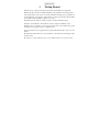
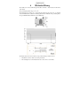
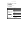
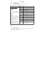
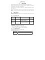
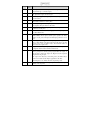
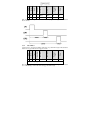
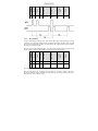
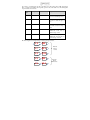
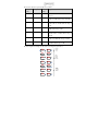
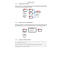
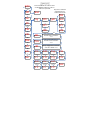
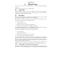
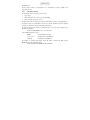
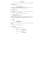
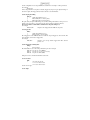
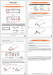
CC320
Trigger Timing Controller
USER MANUAL
Revision 07
Gardasoft Vision Ltd
Castle Acres, Elsworth
Cambridge, CB23 4JQ. UK
Tel: +44 1954 200343
Fax: +44 1954 204343
Web: www.gardasoft.com
1
DISCLAIMER .................................................................................................................... 4
2
SAFETY .............................................................................................................................. 4
3
GETTING STARTED ........................................................................................................ 5
4
MECHANICAL FIXING ................................................................................................... 6
5
CONNECTIONS................................................................................................................. 7
5.1
GENERAL....................................................................................................................... 7
5.2
POWER SUPPLY ............................................................................................................. 7
5.3
DIGITAL INPUTS ............................................................................................................ 7
5.4
DIGITAL OUTPUTS ......................................................................................................... 8
6
OPERATION ...................................................................................................................... 9
6.1
6.2
6.3
6.4
6.5
7
INPUT MODES ................................................................................................................ 9
OUTPUT MODES .......................................................................................................... 10
EXAMPLES ................................................................................................................... 13
COLD BOOT ................................................................................................................. 19
CONFIGURATION FORM ............................................................................................... 20
KEYPAD CONFIGURATION ........................................................................................ 21
7.1
7.2
7.3
STARTUP ..................................................................................................................... 21
COLD START................................................................................................................ 21
CONFIGURATION ......................................................................................................... 21
8
ETHERNET SETUP......................................................................................................... 26
8.1
CONNECTION ............................................................................................................... 26
8.2
IP ADDRESS ................................................................................................................. 26
9
WEBPAGE CONFIGURATION..................................................................................... 30
9.1
MAIN PAGE ................................................................................................................. 30
9.2
CHANNEL CONFIGURATION PAGES.............................................................................. 30
10 UDP AND TCP/IP CONFIGURATION ......................................................................... 31
10.1
COMMUNICATION .................................................................................................... 31
10.2
COMMAND STRUCTURE ........................................................................................... 31
10.3
COMMANDS ............................................................................................................. 32
10.4
COMMAND SUMMARY ............................................................................................. 36
A.
TIMING............................................................................................................................. 37
B.
ERROR CODES ............................................................................................................... 38
1
Disclaimer
Except as prohibited by law:
All hardware, software and documentation is provided on an “as is” basis.
It is essential that the user ensures that the operation of the product is suitable for their
application.
The user must ensure that incorrect functioning of this equipment cannot cause any
dangerous situation or significant financial loss to occur.
Gardasoft Vision Ltd and Gardasoft Products Ltd will not accept any liability for
consequential loss of any kind.
All trademarks acknowledged.
Hardware, software and documentation are Copyright 2007 Gardasoft Products Ltd. Hardware
manufactured by Gardasoft Vision Ltd under license.
2
2.1.1
Safety
General
Please read this before using the CC320 family of products. If in doubt, contact your distributor
or Gardasoft Vision.
The CC320 must not be used in an application where its failure could cause a danger to personal
health or damage to other equipment.
If the equipment is used in a manner not specified by the manufacturer, the protection provided
by the equipment may be impaired.
2.1.2
Electrical
The user must ensure that the potential difference between any combination of applied signals
does not exceed the supply voltage. WARNING: Higher voltages may cause a danger to personal
health.
The CC320 does not have complete tracking isolation of inputs and outputs.
Transients caused by inductive loads must be suppressed external to the CC320.
3
Getting Started
Read the sections on Safety and Operation and check the CC320 fulfils your requirements.
Mount the CC320 as described in “Mechanical Fixing” using a DIN rail or the mounting holes.
Connect the CC320 as in the section on Connections. When the CC320 powers up it should show
two alternating lines on the display to indicate that it is operating properly. Three indicator LEDs
on the outputs should be pulsing in sequence every second.
Check that inputs and outputs are working correctly as described in Troubleshooting.
If required, connect Ethernet to the CC320 and set it up according to the Ethernet section.
Read the section on “Operation.” Use the keypad, a web browser or the CC320 demo program
(available from www.gardasoft.com) to configure the unit.
Visit www.gardasoft.com for Application Notes giving additional information on the use of the
CC320.
Throughout this manual, references to the CC320 refer to all variants in the CC320 range unless
otherwise stated.
The symbol “s” is used to indicate seconds, “ms” for milliseconds and “us” for microseconds.
4
Mechanical Fixing
The CC320 does not have an IP rating and should be mounted so that moisture and dirt cannot
enter the unit.
The operating temperature range is 5oc to 60oc.
The CC320 can be mounted onto a panel using the threaded holes in the base, see diagram
below. The PP703 kit is available for mounting the CC320 on a DIN rail. The top drawing shows
the optional DIN rail fitted. Dimensions are in millimetres.
The CC320 enclosure is a fire enclosure as long as the following conditions are met:
•
The Ethernet connector must not be facing downwards
•
The mounting holes on the underside must be covered or have a screw fitted.
5
5.1
Connections
General
All connections except Ethernet are available on screw terminals.
5.2
Power Supply
The power supply must be 12VDC to 24VDC regulated. The maximum current required is
100mA. The maximum heat dissipation is 2.4W.
5.3
Digital Inputs
The state of each input is shown on an LED next to the connector.
The inputs have a common negative connection, in two groups of four.
Opto-Coupled Input Details
Operating Conditions
Connector
Function
POWER
+
Power supply 12V to 24V
POWER -
Power supply 0V
IP1
Input 1 positive
IP2
Input 2 positive
IP3
Input 3 positive
IP4
Input 4 positive
COM1
Common negative for inputs 1, 2, 3, 4
5V ∗ VIP ∗ 24V
Logic 1
IP5
Input 5 positive
VIP ∗ 2V
Logic 0
IP6
Input 6 positive
VF
1.5V typ
IP7
Input 7 positive
IIN=1.8mA @ VIP=5V
IP8
Input 8 positive
IIN=11.3mA @ VIP=24V
COM1
Common negative for inputs 5, 6, 7, 8
5.4
Digital Outputs
The state of each output is shown by an LED indicator next to the connector.
The operational details are shown in the table below:
Open Drain Output Details
The voltage across the output must
not be greater than 24V and the
output can only sink up to 50mA.
If the output is shorted to a voltage
higher than 5V then the output may
be damaged.
Do not draw more than 50mA from
the +VE connections as this will
affect the internal operation of the
controller.
Connector
Function
GND1
Common 0V for outputs 1, 2, 3, 4
OP1
Output 1 open drain
OP2
Output 2 open drain
OP3
Output 3 open drain
OP4
Output 4 open drain
+VE
Low power regulated output. Maximum
source current 50mA.
GND2
Common 0V for outputs 5, 6, 7, 8
OP5
Output 5 open drain
OP6
Output 6 open drain
OP7
Output 7 open drain
OP8
Output 8 open drain
+VE
Low power regulated output. Maximum
source current 50mA.
Note that the +ve signals are low power supply outputs. These are just to be used for low current
pull ups.
5.4.1
Ethernet Connector
The RJ45 Ethernet connector requires a straight through cable to connect into a network switch,
hub or router. It runs at 10Mbits per second.
6
Operation
The CC320 Trigger Timing Controller has eight digital inputs and eight digital outputs.
All outputs operate independently and are configured separately. Configuration is very flexible to
provide solutions for a wide variety of timing problems.
The configuration can be saved in non-volatile memory so that the CC320 will resume operation
after a power cycle.
The state of each input and output is shown on an LED next to the connector. Pulses are
stretched – a 10us pulse will be shown as a 100ms pulse on the LED, so that it is visible to the
user.
6.1
Input Modes
All inputs are general purpose trigger inputs except for IP1 and IP2, which can be used for an
encoder or as general inputs.
6.1.1
Encoder Operation
The CC320 supports two types of encoder.
Mode
Connections
Operation
Max
frequency
EN 1 - one
wire encoder
IP1 is QEA
Simple encoder provides position
information. All movement is
assumed to be forward.
700KHz
EN 2 – two
wire encoder
IP1 is QEA
Quadrature encoder provides
position and direction information.
200KHz
IP2 is QEB
For 2 wire encoders the CC320 will handle reversed movement correctly. When the belt is in a
reversed position:
•
the letter “b” will be displayed on the front panel
•
triggers for PEt and PEE modes (see below) will be ignored
•
output pulses in PtE, Pet and PEE modes will not be duplicated
6.1.2
Free Running Trigger
An internal input (IP0) can be used as a periodic trigger.
The following parameter can be set.
Parameter
Period
Use
The period (inverse of the frequency) of the simulated
trigger. 0 disables the free running timer.
For example a period of 20ms could be set, which would result in a 50Hz trigger. This can be
used to trigger pulses on any of the outputs.
6.2
Output Modes
Each output operates independently. By combining which outputs are triggered by which inputs
and which mode each output is in, it is possible to configure complex sequences of operation.
Several outputs can be triggered by one input to give synchronous operation, or from separate
inputs to give asynchronous operation of different functions.
For each output, the following parameters can be set.
Parameter
Use
Mode
Specifies how the output operates.
Input
Specifies which input is used for triggering. An output signal OP1 to
OP8 can also be used as a trigger. This parameter can be:
0 for the free running timer
1 to 8 for IP1 to IP8
9 to 16 for OP1 to OP8
Gate Input
Specifies an input which enables/disables the output. This is also used to
specify the number of pulses in “burst” mode. This parameter can be:
0 for none
1 to 8 for IP1 to IP8
9 to 16 for OP1 to OP8
<number of pulses> for burst mode
Pulse Delay
Specifies the delay from trigger to pulse output. This can either be a
time period or a number of encoder pulses, depending on the mode.
Pulse Width
Specifies the width of the pulse output. This can either be a time period
or a number of encoder pulses, depending on the mode.
Retrigger time
The retrigger time is the minimum time from when an output is
triggered to the next time. This can be used to debounce noisy inputs or
when a product sensor fires more than once for one product. The
retrigger time uses the same dimension (encoder pulses or time period)
as the Pulse Delay.
Flags
Specifies other options.
When pulsing, the Pulse Delay and Pulse Width parameters can either be fixed times or can be a
number of encoder pulses.
The following operating modes are available for each output. The Mode Number is used for
Ethernet commands. The Mode Name is used when configuring using the keypad.
Mode
Mode
Name
Operation
0
OFF
The output is set off. If the output is inverted (flag O is set) then the
output will be logic 1, otherwise logic 0.
1
On
The output is set high (on). If the output is inverted (flag O is set) then
the output will be logic 0, otherwise logic 1.
2
Ptt
Pulsed output triggered by a digital input. The delay and pulse width are
set as fixed times.
3
PtE
Pulsed output triggered by a digital input. The delay is a fixed time. The
pulse width is a number of encoder pulses.
4
PEt
Pulsed output triggered by a digital input. The delay is a number of
encoder pulses. The pulse width is a fixed time.
5
PEE
Pulsed output triggered by a digital input. The delay and pulse width are
a number of encoder pulses.
6
Pd
Pulse divider. Every <Pulse Delay> trigger pulses, the output is pulsed
for <Pulse Width> time.
7
Enc
Pulsed output triggered by encoder pulses. The output is pulsed for
<Pulse Width> encoder pulses with the pulses separated by <Pulse
Delay> encoder pulses. The Input and Gate Input parameters are not
used.
8
bur
Burst output. When triggered, <Gate Input> pulses are output. Each
pulse is <Pulse Width> long and the time between the start of one pulse
and the next is given by <Pulse Delay>. The maximum number of
pulses that can be output is 250.
9
FrE
Outputs a constant high frequency square wave. The frequency is
configurable. Further details available from Gardasoft.
10
buF
Buffer an input by making the output the same signal as the input. If
there is gate input set, then the gate input signal enables the output – if
the gate input is off then the output is off. Flag O inverts the output and
Flag G inverts the gate input.
The output can be delayed by a fixed time given by the <Pulse Delay>
parameter. Note that any Gate Input is applied before the delay.
The E flag can be set to indicate when the output changes state.
11
buE
Same as buF mode, except the output signal can be delayed by a given
number of encoder pulses.
Each output also has the following flags which specify other options. For Ethernet commands,
multiple flags can be set by adding the flag values together.
Flag
value
6.2.1
Flag
Name
Operation
Operation
when flag = 0
when flag = 1
1
I
Trigger off leading edge of
input.
Trigger off trailing edge of
input.
2
O
Output is normally low,
going high when pulsing.
Output is inverted. It is
normally high, going low
when pulsing.
4
G
If a gate input is specified,
the input must be high to
enable triggers.
If a gate input is specified, the
input must be low to enable
triggers.
8
E
No Ethernet message.
Send message on Ethernet
when triggered.
16
F
Triggers are ignored until
output pulse is complete.
FIFO output mode. Multiple
triggers are queued up.
32
R
Resync mode disabled.
Resync Mode enabled.
64
P
Default to pulse in resync
mode.
Default to no pulse in resync
mode.
Burst Mode
In burst mode, an output will pulse several times in response to a trigger. The periods are timed
(not encoder counts).
The following parameters are used:
•
Mode is 8 for burst mode
•
Gate Input specifies the number of pulses (1 to 250)
•
Pulse Width specifies the pulse width
•
Pulse Delay specifies the separation between the start of one pulse and the start of the next
Pulse Delay must be longer than Pulse Width.
6.2.2
Ethernet Message Flag (E)
When the CC320 is used to trigger a camera, the image processing can either be triggered by the
acquisition of an image or by an Ethernet message sent from the CC320.
When a trigger is received it is assigned a unique tag number (an incrementing number from 0 to
255). Using the GT Ethernet command and the Ethernet Message flag, the CC320 will send the
tag number in a message to the host computer to say that a trigger has occurred.
The message has the form:
Evt<channel>,<tag>
where <channel> is the channel number from 1 to 8 and <tag> is a number from 0 to 255.
Multiple tag messages may be sent in one packet, separated by “;”.
6.2.3
Resync Flag (R)
Reject gate operation usually needs to be synchronised to the original product trigger. However
image processing can take a variable length of time to complete, so rejects based on when the
processing result is available will not be accurately timed. The Resync flag allows pass/fail
results to be re-synchronised to the original trigger.
There are two types of reject gate:
•
A pulse is required to reject a product (set the P flag)
•
A pulse is required to stop a product being rejected (don’t set the P flag)
The Resync Flag should be used with the Ethernet Message flag. The host computer will receive
a tag number message, process the image and then send a pass/fail result (as an SN command)
back to the CC320. The CC320 will match the message to the original trigger and time the
pass/fail output pulse accurately.
If an SN command is not received in time, then the product will be rejected, and an error code
output.
6.2.4
FIFO Flag (F)
The FIFO flag is used for systems where there can be more than one product between the trigger
point and reject gate. This is usually used with the Resync flag, so that each product has its own
pass/fail result.
If the FIFO flag is not set, then an output cannot be re-triggered until the previous pulse has
completed. Others triggers in this time will be ignored.
If the FIFO flag is set, then multiple triggers are stored in the CC320 and a pulse is generated for
each trigger at the correct time.
6.2.5
Pulse Flag (P)
The Pulse flag is used to select whether a pulse is needed to reject or to accept a product when
the Resync flag is set. When not set, a pulse is required to reject product. If a pass/fail message is
not received in Resync mode, the CC320 will default to rejecting the product.
6.3
Examples
6.3.1
Sequenced Pulses
A sensor detects product presence. There are two cameras which need to take an image after
different delays. The leading edge of IP1 is used as the trigger. OP1 triggers the first camera after
100ms. OP2 triggers the second camera after 200ms. Both camera triggers are positive pulses.
Flags
Retrigger
Time
Pulse Width
Pulse Delay
Gate Input
Input
Mode
Output
1
2
1
0
100ms
100us
0
0
2
2
1
0
200ms
100us
0
0
Both outputs are set into pulse mode. Two different delays give the timing difference between
the two cameras.
6.3.2
Gated Pulses
1
100us
0
Flags
0ms
Retrigger
Time
Gate Input
Input
0
Pulse Width
2
Pulse Delay
1
Mode
Output
A camera needs to be triggered at 25Hz continuously, except when IP1 is high to indicate that the
machine has stopped. The camera is triggered on OP1.
G (4)
Set free running trigger to 25Hz.
OP1 will trigger continuously at 25Hz only when IP1 is low. Note that Flags = 4 to invert the
sense of IP1. If Flags = 0, then OP1 will only trigger when IP1 is high.
6.3.3
Belt Position Triggering
5
4
0
2000
encoder
counts
100us
1
5
4
0
4000
encoder
counts
100us
1
Flags
Retrigger
Time
Pulse Width
Pulse Delay
Gate Input
Input
Mode
Output
On a conveyor with an encoder, a sensor detects product presence. There are two cameras which
need to take an image at fixed distances along the belt. The camera trigger pulses must be fixed
width for exposure control. The trailing edge of IP4 is used as the trigger. OP1 triggers the first
camera after 2000 encoder counts. OP2 triggers the second camera after 4000 encoder counts.
Both camera triggers are negative pulses.
0
I, O
(3)
0
I, O
(3)
Set input mode to 2-wire encoder.
Both outputs are set into pulse mode. The pulse delay is a number of encoder pulses and the
pulse width is a fixed time. The flags specify the trailing edge of the trigger signal and that the
output pulse is active low.
6.3.4
Pulse Burst
A sensor on IP1 detects product presence. Four images need to be taken from one camera using
four different lights at 40ms intervals. OP1, OP2, OP3, OP4 are used to output triggers to turn on
the four lights in sequence. OP5 is used to trigger the camera four times.
0
0
40ms
0
0
3
2
1
0
80ms
40ms
0
0
4
2
1
0
120ms
40ms
0
0
5
8
1
4
40ms
100us
0
0
Flags
Pulse Width
40ms
40ms
Retrigger
Time
Pulse Delay
0ms
0
Gate Input
0
1
Input
1
2
Mode
2
2
Output
1
OP1 to OP4 are pulsed for 40ms in sequence. As each one is pulsed, OP5 is also pulsed for a
short time to trigger the camera (Gate Input = 4 specifies four pulses).
6.3.5
Simple FIFO Mode
A sensor on IP1 detects product presence. After a delay OP1 triggers a camera. There may be
several products between the sensor and the camera.
The CC320 needs to store each of the triggers and then output a pulse after the correct delay.
6.3.6
2
1
0
10 seconds
100us
0
Flags
Retrigger
Time
Pulse Width
Pulse Delay
Gate Input
Input
Mode
Output
1
F (16)
Resync Mode
A sensor on IP1 detects product presence. After a delay OP1 triggers a camera. Image processing
software processes the image (which can take a variable length of time) and then sends a pass/fail
message to the CC320. The pass/fail is re-synchronised to the original product presence and the
reject gate is opened if necessary.
1
2
1
0
200ms
100us
0
2
2
1
0
10 seconds
1 second
0
Flags
Retrigger
Time
Pulse Width
Pulse Delay
Gate Input
Input
Mode
Output
The reject gate is on OP2 and pulses high to reject the product. Products take 10 seconds to travel
from the sensor to the reject gate and take 1 second to move past the reject gate.
E,R,P
(104)
10 seconds after a trigger, OP2 is set to pulse for 1 second to reject a product.
The camera trigger has the “Send trigger message” flag set. So that the product is detected, a
message is send to the image processing software. The image processing software must use the
GT command to receive these messages.
The image processing has to send a pass/fail message before the reject gate is reached by the
product. As well as “Resync mode” the “default to pulse” flag is set. This means that if the image
processing software does not send a pass/fail message OP2 is pulsed anyway.
In this example, three product triggers were received. The camera was triggered using OP1.
An Ethernet message with tag number 10 was sent to the host computer when the first trigger
was received, but for some reason a reply was not received, so the product was rejected for failsafe operation. After the second trigger a Tag 11 message was sent, with the reply “SN2,11,1”
(OP2, tag 11, pass) so the reject pulse on OP2 was cancelled. After the third trigger a Tag 12
messages was sent, with the reply “SN2,12,0” (OP2, tag 12, fail) so the reject pulse on OP2 was
not cancelled.
6.3.7
Resync and FIFO Mode
This uses the same situation as the previous example, but products are 4 seconds apart, so that
when a product is detected, there are already two others travelling towards the reject gate.
Image processing software processes the image (which can take a variable length of time) and
then sends a pass/fail message to the CC320. The pass/fail is re-synchronised to the original
product presence and the reject gate is opened if necessary.
2
1
0
200ms
100us
0
2
2
1
0
10 seconds
1 second
0
Flags
Retrigger
Time
Pulse Width
Pulse Delay
Gate Input
Input
Mode
Output
6.4
1
E, F,
R, P
(120)
Cold Boot
A cold boot function is available to reset the CC320 to a known state. The unit can be cold
booted as follows:
•
•
•
Press and hold the SEL and DOWN buttons when powering up the unit
Sending an Ethernet command
Pressing a button on an internal webpage
When the unit is cold booted it is set to the following state:
•
•
•
•
•
•
•
•
•
•
IP0 (free running trigger) is set up as a 1Hz internal trigger
The unit is set up for no encoder input
OP1 triggers from IP1, delay for 100ms then pulse for 100ms
OP2 triggers from IP2, delay for 100ms then pulse for 100ms
OP3 triggers from IP3, delay for 100ms then pulse for 100ms
OP4 triggers from IP4, delay for 100ms then pulse for 100ms
OP5 triggers from IP5, delay for 100ms then pulse for 100ms
OP6 triggers from IP0, delay for 100ms then pulse for 100ms
OP7 triggers from IP0, delay for 200ms then pulse for 100ms
OP8 triggers from IP0, delay for 300ms then pulse for 100ms
6.5
Configuration Form
1
2
3
4
5
6
7
8
Free running timer period:
Encoder mode:
Tick when
complete
Flags
Retrigger
Time
Pulse Width
Pulse Delay
Gate Input
Input
Mode
Output
Before configuring the CC320, work out all the values and fill in a copy of the form below. This
form is available on the CC320 page at www.gardasoft.com.
7
Keypad Configuration
The CC320 is set up using the push buttons and display on the front of the unit. The set up is
non-volatile, so the CC320 will resume the same operation after a power cycle.
7.1
Startup
On power up, the CC320 will display “8.8.8.” to test the display is working, then “CC”, “320”,
followed by the version number, eg “001”, and then will be ready for operation. To show that the
unit is operating normally, a moving pattern is drawn on the display.
7.2
Cold Start
In the unlikely event that the non-volatile
memory becomes corrupt the CC320 may
not start up properly. In this case the
memory can be cleared by powering up
the CC320 while holding down the
SELECT and DOWN buttons. The
CC320 will display “COL” for about 2
seconds while the memory is cleared.
7.3
---
SEL
OP I
SEL
UP/DOWN
OP2
SEL
OP8
SEL
Set up an
output
channel
Configuration
To configure the controller from the
keypad, press and hold SEL for 1 second.
“OP1” will be displayed.
The overall structure of keypad
configuration is given to the right.
UP/DOWN
EnC
SEL
Set up
encoder
mode
SEL
Set up
Ethernet
SEL
Set up
free
running
timer
UP/DOWN
The UP and DOWN buttons are used to
change the selection and to change
numeric values. The SEL button is used
to confirm a selection and move to the
next item. When configuration is
complete, “End” is displayed.
See the section on the Ethernet for setting
up IP addresses.
7.3.1
EtH
UP/DOWN
FrE
Setting Numeric Values
When the CC320 displays numeric values for the user to change, the right hand digit will be
flashing to indicate that the Up and Down buttons can be used to change the value.
To be able to set timing and encoder count values (for pulse delay, pulse width and retrigger
time) a scheme is used where the exponent (power of ten) of the value is set. For timings, the
exponent values are as follows:
Exponent
value
Multiplier
Number format
Range of values
E0
1
999.
Values are displayed in seconds
from 1s to 999s in steps of 1s.
E-1
0.1
99.9
Values are displayed in seconds
from 0.1s to 99.9s in steps of
0.1s.
E-2
0.01
9.99
Values are displayed in seconds
from 0.01s to 9.99s in steps of
0.01s.
E-3
0.001
999.
Values are displayed
milliseconds from 1ms
999ms in steps of 1ms.
E-4
0.0001
99.9
Values are displayed in
milliseconds from 0.1ms to
99.9ms in steps of 0.1ms.
The flow diagram for entering timings on the keypad is given below.
E0
SEL
999.
SEL
SEL
99.9
SEL
SEL
9.99
SEL
SEL
999.
SEL
99.9
SEL
UP/DOWN
E-1
Enter the
time in
seconds
UP/DOWN
E-2
UP/DOWN
E-3
Enter the
time in
milliseconds
UP/DOWN
E-4
SEL
in
to
For encoder counts, the exponent values are as follows:
Exponent
value
Multiplier
Number
format
Range of values
E0
1
999.
Values are from 1 count to 999 counts in
steps of 1.
E1
10
9.99
Values are displayed in K from 0.01K
counts to 9.99K counts in steps of 0.01K.
E2
100
99.9
Values are displayed in K (thousands) from
0.1K counts to 99.9K counts in steps of
0.1K.
E3
1000
999.
Values are displayed in K from 1K counts to
999K counts in steps of 1K.
E4
10000
9.99
Values are displayed in M (millions) from
0.01M counts to 9.99M counts in steps of
0.01M.
E5
100000
99.9
Values are displayed in M from 0.1M
counts to 99.9M counts in steps of 0.1M.
E6
1000000
999.
Values are displayed in M from 1M counts
to 999M counts in steps of 1M.
The flow diagram for entering encoder counts on the keypad is given below.
E0
SEL
999.
SEL
SEL
9.99
SEL
SEL
99.9
SEL
SEL
999.
SEL
SEL
9.99
SEL
SEL
99.9
SEL
SEL
999.
SEL
UP/DOWN
E1
UP/DOWN
E2
Enter
encoder
count in
ones
Enter
encoder
count in
thousands
UP/DOWN
E3
UP/DOWN
E4
UP/DOWN
E5
UP/DOWN
E6
Enter
encoder
count in
millions
7.3.2
Setting Up Encoder Mode
Set the encoder mode from the keypad as follows. Press and hold the SEL button until the
display shows “OP1”. Use the UP and DOWN buttons to select “Enc” then press SEL. Select the
encoder mode using UP and DOWN and press SEL.
Enc
SEL
Press and
hold SEL for
1 second.
Then use
UP/DOWN to
select “Enc”,
then press
SEL
7.3.3
non
UP/DOWN
n1
SEL
UP/DOWN
n2
End
Select
encoder mode
and then
press SEL
Setting Up The Free Running Timer
Set the free running timer period from the keypad as follows. Press and hold the SEL button until
the display shows “OP1”. Use the UP and DOWN buttons to select “FrE” then press SEL. Set
the free running timer period. See section 7.3.1 for a description of how to set the time period.
FrE
SEL
Press and
hold SEL for
1 second.
Then use
UP/DOWN to
select “FrE”,
then press
SEL
7.3.4
Set up free
running timer
period as in
Section 7.3.1
End
Setting Up An Output Channel
The overall structure for setting up an output channel is given below. Configuration mode must be entered
once for each output channel to be set up.
The output mode names are given in Section 6. Depending on the selected mode, the user will be prompted to
enter a time or a number of encoder pulses as appropriate for the pulse delay and pulse width.
The flag names are given in Section 6. A minus (“-“) sign indicates that the flag is not set. So “F-I” indicates
that the I flag is not set and “F I” indicates that it is set.
OP2
SEL
Off
SEL
Press and hold SEL for 1 second. Then
use UP/DOWN to select from “OP1” to
“OP8”, then press SEL
Only for “bur” mode the
Gate parameter is a
number from 2 to 250
End
250
UP/DOWN
On
trg
UP/DOWN
gAt
non
UP/DOWN
Ptt
UP/DOWN
IP0
SEL
SEL
PtE
IP1
UP/DOWN
SEL
SEL
IP8
UP/DOWN
IP8
SEL
dEL
Set up pulse delay time or
encoder count as in Section
7.3.1
PUL
Set up pulse width time or
encoder count as in Section
7.3.1
rEt
Set up retrigger time or encoder
count as in Section 7.3.1
Enc
F-I
F-O
UP/DOWN
UP/DOWN
bur
FI
FO
Fg
F-F
F-r
F-P
PEt
UP/DOWN
PEE
UP/DOWN
Pd
IP1
UP/DOWN
UP/DOWN
FF
SEL
SEL
UP/DOWN
UP/DOWN
Fr
F-g
SEL
SEL
UP/DOWN
UP/DOWN
FP
F-E
SEL
UP/DOWN
FE
SEL
End
8
Ethernet Setup
You may need to ask your network administrator for advice about setting up the Ethernet
connection.
Ethernet set up is not affected by cold booting the CC320.
8.1
Connection
The Ethernet link uses a 10 base-T connection on an RJ45 connector. The CC320 will usually be
connected to a network switch (or hub or router). It is also possible to connect it direct into the
network port on a PC by using a swapover cable.
8.2
IP Address
The CC320 needs an IP address to communicate over Ethernet. There are two ways to get an IP
address; either a fixed address configured in the unit or using DHCP.
Most networks use a DHCP server. If there is a PC on the network, You may be able to find out
whether a PC on the same network uses DCHP as follows:
•
Go to Control Panel
•
Select Network Connections
•
Right click on Local Area Connection. Select Properties
•
From the list, select Internet Protocol (TCP/IP), press Properties
If “Obtain an IP address automatically” is set, then DHCP is probably used. However, there may
be an alternative fixed IP address on the “Alternative Configuration” tab.
You can find out what IP address is being used by a PC at any time by:
•
Go to Control Panel
•
Select Network Connections
•
Right click on Local Area Connection. Select Status
•
Select the Support tab. The IP address is displayed
When using a fixed IP address, you must ensure that you use an IP address that is not being used
by any other device on the network. It is usual to keep the first three numbers of the IP address
the same as other devices and to change only the last number. For example, if you have a
network consisting of a PC (IP address 192.168.1.35) and two CC320s, you might give them
addresses 192.168.1.201 and 192.168.1.202.
For DHCP mode, the CC320 acquires its IP address, subnet mask and gateway address from a
DHCP server. Otherwise the CC320 has a fixed IP address, subnet mask and gateway address.
8.2.1
Setting DCHP or an IP Address from the Keypad
Set DHCP mode from the keypad as follows. Press and hold the SEL button until the display
shows “OP1”. Use the UP and DOWN buttons to select “ETH” then press SEL. The display will
either show “FIP” for a fixed IP address or “dhC” for DHCP. Use the UP and DOWN buttons to
select “dhC” and press SEL.
For a fixed IP address, select “FIP” and press SEL. The user will be prompted to enter four bytes
of the IP address, four bytes of the address submask and then four bytes of the gateway address.
dhc
SEL
End
SEL
255
Set DHCP
mode
UP/DOWN
FIP
SEL
IP I
SEL
IP2
SEL
255
IP4
SEL
255
Sb2
SEL
255
Sb4
SEL
255
gt2
SEL
255
gt4
SEL
255
Set IP
address
SEL
IP3
SEL
255
SEL
SEL
SbI
SEL
255
SEL
Set IP
submask
SEL
Sb3
SEL
255
SEL
SEL
gtI
SEL
255
SEL
gt3
SEL
255
SEL
Set
gateway
address
SEL
SEL
End
When an IP address has been assigned using DHCP, the address can be read from the keypad as
follows. Press and hold the SEL button until the display shows “OP1”. Use the UP and DOWN
buttons to select “ETH” then press SEL. Use the UP and DOWN buttons to select “rIP” and
press SEL. Keep pressing SEL and read the four values of the IP address. The example below
shows the IP address 192.168.1.71.
dhc
UP/DOWN
FIP
UP/DOWN
Show IP
address
rIP
SEL
IP I
SEL
192
SEL
IP2
SEL
168
IP4
SEL
71
SEL
IP3
8.2.2
SEL
1
SEL
SEL
End
Setting DCHP or an IP Address from the Keypad
The DCHP mode or a Fixed IP address can be configured from the Ethernet Demo application
which can be downloaded from the CC320 page at www.gardasoft.com.
Communication
All the features below are implemented in a demonstration program available from
www.gardasoft.com.
8.2.3
Automatic Sensing
The CC320 will send out a message on three events:
•
On power up
•
When an IP address is received or renewed by DHCP
•
When an enquiry message is received
On the first two events, the message is broadcast. On the third it is a reply to a single IP address.
An enquiry message is a UDP packet from source port 30310, destination port 30311 with the
message body “Gardasoft Search” (8-bit ASCII, 13 characters).
The message output by the CC320 is a UDP packet from source port 30311, destination port
30310. It is formatted as:
Gardasoft,CC320,000000,111111111111,22222222
(8-bit ASCII, 44 characters), where
000000
the serial number of the unit
111111111111
the MAC address in 6 HEX bytes
22222222
the IP address in 4 HEX bytes
For example for CC320 serial number 12345, IP address 192.168.1.103, MAC address
00.0B.75.01.80.99 the packet will contain
Gardasoft,CC320,012345,000B75018099,C0A80167
9
Webpage Configuration
The CC320 has a small webserver inside, so that it can be configured from a standard web
browser, such as Internet Explorer.
The IP address of the CC320 must be known (see the section on “Ethernet Setup.” Open a web
browser window and type the IP address (for example 192.168.1.71) of the CC320 into the URL
box at the top. The main page of the CC320 webserver should be shown.
9.1
Main Page
The main page shows general information about the CC320 and can be used to set up the Encoder mode and
the Free Running Timer period. Press the Submit button to update the CC320 and save the changes to nonvolatile memory.
Links are provided to the channel configuration pages.
9.2
Channel Configuration Pages
There is one Channel Configuration Page for each output channel. All the parameters for each output channel
can be set up. Press the Submit button to update the CC320 and save the changes to non-volatile memory.
10
10.1
UDP and TCP/IP Configuration
Communication
The CC320 can be configured via the Ethernet connection using UDP or TCP/IP. A
demonstration program with source code can be downloaded from www.gardasoft.com.
Communication consists of commands sent by the host (controlling PC). All output generated by
the command is returned in reply UDP or TCP/IP packets. The last character sent is “>” (“greater
than” symbol). Once this is received, the host knows that the command has been completed. It is
recommended that the host waits for the “>” symbol before sending the next command. UDP
communications are not guaranteed to arrive, so the host software must be able to cope with lost
messages.
Using the GT command, a host can request that a message is sent to it whenever an error occurs.
Commands from a host should be sent to destination port 30313. Any port number can be used
for the source port. Replies from the C320 will be sent to the source port.
A TCP/IP connection will timeout and close if it is idle for more than 10 seconds. The host must
send regular “heartbeat” commands (eg “VR”) to keep the link open.
10.2
Command Structure
Several commands can be put into one command line by separating them by a semi-colon (“;”).
A carriage return character should be sent to terminate the command line. The CC320 will send
any replies to the commands and then send a ‘>’ character to indicate that the command line has
been completed.
Commands comprise a code of two letters followed by the parameters (if any) needed for the
command. Spaces in the commands are ignored.
Numeric parameters are separated by a comma (“,”). For a parameter which is a time period the
default units are milliseconds. “s”, “ms” or “us” can be added to the end of the number to
indicate seconds, milliseconds or microseconds. “K” can be used for 1000 encoder pulses and
“M” for 1000000 encoder pulses. For example:
Parameter
Meaning
0.1
0.1 milliseconds
200us
200 microseconds
0.1s
0.1 seconds
100
100 encoder pulses
15.5K
15500 encoder pulses
14.5M
14500000 encoder pulses
Encoder values can be up to 1,000,000,000. Time periods can be from 0.1ms to 100 seconds in
steps of 0.1ms.
Note that parameters are in “USA/UK” format so that one half is written “0.5” not “0,5”
The command codes and their meaning are described below. The single upper case letter codes
for the parameters are also shown, followed by lower case letters denoting the numeric argument.
Error number
Reason
Err 1
A parameter value is invalid
Err 2
Command not recognised
Err 3
Numeric value is wrong format
Err 4
Wrong number of parameters
Err 17
Can’t save settings to EEPROM
Any changes made using Ethernet commands are not saved permanently until the AW
command has been issued.
10.3
Commands
Show the firmware version
VR
Outputs the version number of the firmware, for example “001”.
Clear Configuration
CL
Clears the configuration to the cold boot state.
Save Configuration
AW
Saves the configuration to non-volatile memory. When the CC320 is turned off and on this
configuration will be restored.
Show Configuration
ST
The current configuration is shown. The first line gives the encoder mode and the internal trigger
timing. Then the configuration of each of the outputs is given, one per line. The flags are shown
as lower case letters if not set and upper case if set. Example output from this command is:
No encoder, trigger period =
1.000s
OP1: MD=2, IP=1, GT=-, DL=100.00ms, PL=100.00ms,
OP2: MD=2, IP=2, GT=-, DL=100.00ms, PL=100.00ms,
OP3: MD=2, IP=3, GT=-, DL=100.00ms, PL=100.00ms,
OP4: MD=2, IP=4, GT=-, DL=100.00ms, PL=100.00ms,
OP5: MD=2, IP=5, GT=-, DL=100.00ms, PL=100.00ms,
RT=
RT=
RT=
RT=
RT=
0.00ms,
0.00ms,
0.00ms,
0.00ms,
0.00ms,
iogefrp
iogefrp
iogefrp
iogefrp
iogefrp
OP6: MD=2, IP=0, GT=-, DL=100.00ms, PL=100.00ms, RT=
OP7: MD=2, IP=0, GT=-, DL=200.00ms, PL=100.00ms, RT=
OP8: MD=2, IP=0, GT=-, DL=300.00ms, PL=100.00ms, RT=
0.00ms, iogefrp
0.00ms, iogefrp
0.00ms, iogefrp
Enable Ethernet Messages
GTm
m
= 0 to disable Ethernet messages
= 1 to enable Ethernet messages
When Ethernet messages are enabled, any trigger tag messages and error reports are sent to the
most recent UDP or TCP address from which a command has been received.
Read any Error Messages
GR
If Ethernet messages are not enabled, the last error number can be read by this command. The
reply is of the form:
Err 45
Error 45 was the last error
Err 0
No error has occurred since the last GR command
Set/Clear the Webpage Password
EY
EY asc1, asc2, asc3, asc4, asc5, asc6
This command sets the password required to access the webpages. If EY is entered on its own
then the password is cleared. There are six optional parameters, which are ASCII values for a
password from one to six letters. A value of 65 is ‘A’, 66 is ‘B’, etc to 90 is ‘Z’.
Set Pass/Fail
SNc,t,p
c
which output channel (1 to 8)
t
the trigger tag number
p
1 = pass, 0 = fail
For Resync mode, this command returned the pass/fail state of image processing for the given
trigger tag.
For example:
SN3,76,1 Output 3, trigger tag 76 is a pass
Set the output mode
RSc,m,i,g,f
c
which output channel (1 to 8)
m
mode
i
which trigger input: 0 for free running timer
1 to 8 for IP1 to IP8
9 to 16 for OP1 to OP8
g
which gate input:
0 for none
1 to 8 for IP1 to IP8
9 to 16 for OP1 to OP8
f
flags
Sets the configuration for an output channel. See section 6 for a description of these parameters.
For example:
RS4,3,5,0,2
will set output channel 4 to be pulse mode (Ptt), triggered by input 5, no gate input and flags = 2
(invert the output). The flags parameter must be entered as a decimal number.
Set the output pulse timing
RTc,p,d
c
which output channel (1 to 8)
p
Pulse width (time or encoder pulses)
d
Pulse delay (time or encoder pulses)
The pulse delay and pulse width timings are set. These timings will either be a time period or a
number of encoder pulses, as previously set by the mode parameter of the RS command.
The mode should be set with the RS command before the pulse timing is set.
For example:
RT2,3ms,5K
Output 2, 3ms output pulse after 5000 encoder pulses
Set retrigger time
RRc,r
c
which output channel (1 to 8)
r
Retrigger time or encoder pulses
The retrigger time is the minimum time from when an output is triggered to the next time. The
mode should be set before the retrigger time.
For example:
RR4,10ms
Output 4 won’t accept another trigger until 10ms after the
previous one
Set the internal free running timer
RB1,p
p
Period of timer
The internal timer is set to run at the specified time period. For example:
RB1,1ms Set period to 1ms (1000Hz)
RB1,3s
Set period to 3s (once per 3 seconds)
RB1,40 Set period to 40ms (25Hz)
If the period is zero, then the internal timer is turned off.
Set encoder mode
REe
e
Sets the encoder type.
Set an output
= 0 to turn encoder off
= 1 for a one-wire encoder
= 2 for a two-wire encoder
RVc,v
c
v
which output channel (1 to 8)
= 0 to set the output to a logic 0 (logic 1 if O flag is set)
= 1 to set the output to a logic 1 (logic 0 if O flag is set)
Sets an output to a given logic level. This is a temporary override which will be cancelled the
next time the output is pulsed or if its configuration is changed.
If the “O” configuration flag is set for an output the the output will be inverted.
Read/change the encoder count
EN
Read the encoder count
EN0,c
Adjust the encoder count backwards
EN1,c
Adjust the encoder count forwards
This command returns “VL” and the encoder count. For example, the reply will be “VL200” if
200 encoder counts have been received since the CC320 was turned on. The count is a 32 bit
unsigned number, so it will wrap to 0 when it reaches 232.
EN0 adjusts the encoder count backwards. It has the same effect as if the encoder moved
backwards by this distance. It works for 1-wire and 2-wire encoders.
EN1 adjusts the encoder count forwards. This has the same effect as the encoder moving
forwards, so might have an effect on outputs which use the encoder for timing. For example in
PEE mode a pulse may become due to start or stop.
For example, the commands:
EN
returns VL0
EN1,25 ‘ Move forward 25 count
EN
returns VL25
EN0,10 ‘ Move backwards 10
EN
returns VL15
EN0,40 ‘ Move backwards 40
EN
returns VL4294967271 because the count has wrapped to 232 – 25.
Show the state of an input.
RIi
i
which input channel (1 to 8)
Replies “VL0” if the input is logic 0 and “VL1” if the input is on.
Show the state of an output
ROc
c
which output channel (1 to 8)
Replies “VL0” if the output is logic 0 and “VL1” if the output is on.
Simulate an Input Pulse
MPi
c
which input channel (0 to 8)
Generates a simulated pulse on an input. The input can be a physical input or the free running
timer (IP0).
Disable Keyboard
KBd
d=0
Enable keyboard
d=1
Disable keyboard
In some applications it may be necessary to disable the keyboard so that operation can only be
controlled from the Ethernet port. The setting of this command is restored after a power cycle.
10.4
Command Summary
Function
Show the firmware version
Clear all configuration
Show configuration
Make configuration non-volatile
Read any error messages
Enable Ethernet messages
Set webpage password to “AB”
Set pass/fail
Set pulse timing
Set retrigger time
Set output mode
Set internal trigger period
Set encoder mode
Read the encoder count
Sets an output
Read state of an input
Read state of an output
Simulate an input pulse
Disable keyboard
Command Syntax
VR
CL
ST
AW
GR
GTm
EYa1,a2
SNc,t,p
RTc,p,d
RRc,r
RSc,m,i,g,f
RB1,p
REe
EN
RVc,v
RIi
ROc
MPi
KBd
A. Timing
The following timings apply for CC320 V016. All these timing assume that a single output
channel is being used. Simultaneous events on multiple inputs can cause some variation.
Typically this can vary the timing by up to 100us for each input.
Pulse widths below 4ms are repeatable to within 1us and are not subject to variation even with
other simultaneous events. Pulse widths above 4ms are repeatable to within 100us and are
subject to variation.
PTT mode pulses in the following conditions have higher priority and better timing:
•
Delay = 0, pulse width <= 4ms
•
Delay + pulse width <= 4ms and O flag not set
For example with OP1 to OP4 all meeting the first condition:
OP1 has delay 24us +/-4us
OP2 has delay 29us +/-4us
OP3 has delay 34us +/-4us
OP4 has delay 40us +/-4us
The reply time of a simple Ethernet command (for example the GT command) is around 1.8ms
for UDP and 2.8ms for TCP.
In buffer mode there is a minimum delay of 20us between the input changing and the output
changing.
B. Error Codes
Error codes may be displayed by the CC320 or returned as a reply to an Ethernet message. These
are shown as “Enn”, where nn gives the number of the error. To cancel the error message, press
“SEL”.
EEPROM is the non-volatile memory used to save the configuration and Ethernet settings. If the
EEPROM errors occur repeatedly, then the controller may need to be returned for repair.
The error codes are:
Error number
Reason
Err 1
Ethernet command: A parameter value is invalid
Err 2
Ethernet command: Command not recognised
Err 3
Ethernet command: Numeric value is wrong format
Err 4
Ethernet command: Wrong number of parameters
Err 5
Can’t read EEPROM.
Err 6, 12, 16
EEPROM corrupt. The configuration has been cleared.
Err 8, 25
Can’t read settings from EEPROM
Err 9, 17
Can’t save settings to EEPROM
Err 13
SN command: the resync event cannot be found. The
channel/tag values may be wrong or the delay period may
have completed.
Err 49
Ethernet hardware not working
Err 51
Can’t read Ethernet settings from EEPROM, so these may
be incorrect.
Err 52
Can’t save Ethernet settings to EEPROM.
Err 81
Too many FIFO events have been used and the CC320 has
run out of storage.
Gardasoft LED Lighting Controllers
The products available at the time of writing include the following. Other products are also
available. See www.gardasoft.com for details of the current range.
PP500 Range
•
•
•
2 output channels up to 10A each
2 digital inputs
Front panel configuration
PP500
PP520
PP500F
PP520F
Lighting controller
Lighting controller with Ethernet control
Lighting controller with fast pulsing
Lighting controller with Ethernet control, fast pulsing
PP701
DIN Rail mounting clip for PP500 and PP500F ranges
PP420 Range
•
Same as the PP500 range but with 4 channels, no front panel
PP420
PP420F
Lighting controller with Ethernet control
Lighting controller with Ethernet control, fast pulsing
PP820 Range, PP860C Range
•
•
•
•
High current, high accuracy controller
8 output channels up to 20A each
Pulses repeatable to 0.1 microseconds
RS232 or Ethernet configuration
Machine Vision Timing Controller
CC320 Controller
•
•
•
•
•
•
8 digital inputs
8 digital outputs
1 or 2 wire Encoder input
Very flexible operation
Ethernet control
Front panel configuration
PP703
DIN Rail mounting clip for CC320