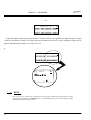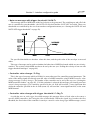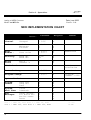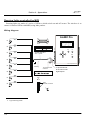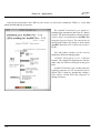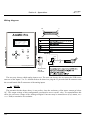
1
I rcam
documentation
AtoMIC Pro
SENSORS / MIDI
INTERFACE
User’s Manual
AtoMIC Pro
<
AtoMIC Ready
>
Patch: 01-My Patch
File / MIDI / Prefs
Dump Out / Spy
Dec.
Inc.
Valid.
32 channels Analog to MIDI Converter
I rcam
documentation
© Copyright 1998-2002, IRCAM. All rights reserved.
This manual must not be copied, neither in its entirety, nor partially, without written permission from
IRCAM.
This user manual was written by Emmanuel Fléty and Bruno Bossis, and translated by Emily Morin. It was
kindly proofread by Marc Battier, head of documentation.
The Analog to MIDI interface AtoMIC Pro was designed and developed by Emmanuel Fléty.
Third edition, June 2002. Version 2 of the documentation.
This documentation corresponds to version 2 of the AtoMIC Pro interface, version 2.02 of the internal
assembler software and version 2 of the Max patches and objects.
AtoMIC Pro is a trademark of IRCAM.
Max is a trademark of IRCAM.
Apple Macintosh is a registered trademark of Apple Computer, Inc.
For further information, please contact :
Paola Palumbo
Marketing department
IRCAM
1, place Igor-Stravinsky
75004 Paris
France
Tel. (33) 01 44 78 14 87
Fax (33) 01 44 78 43 55
E-mail : [email protected]
IRCAM
1, place Igor-Stravinsky
75004 Paris
France
Tel. (33) 01 44 78 48 43
Fax (33) 01 44 78 15 40
Safety instructions
!
Warning
Notes
Before using the device, make sure you have read the
following instructions carefully, as well as the instructions
for use.
Do not open or modify the device or its mains adapter,
except when this manual tells you exactly how to do so.
Do not try to repair the interface or the components inside
it, except when this manual recommends it. Please contact
IRCAM in case of problems.
Do not use the device or store it in the following
conditions :
- Extreme temperatures, or exposed to direct sunlight.
- Damp areas.
- Dusty areas.
- Areas prone to strong vibrations.
If you replace the main adapter, make sure its output
polarity, voltage and current are correct.
Do not insert any objects or pour any liquid into the
device.
Protect the device against violent shocks.
Before using the device in a foreign country, make sure the
main adapter provided is compatible with the main supply.
If the device will not be used for a long period, disconnect
the adapter from the mains.
Never place heavy objects on the device.
Never touch the device or the adapter with wet hands when
it is plugged in.
Before moving the device, make sure the mains adapter
and/or any external elements are disconnected from the
unit.
Before cleaning the device, make sure the mains adapter is
electrical unplugged.
If the device is used somewhere where it is likely to be
struck by lightning, unplug it.
© Copyright 1998-2002, IRCAM. All rights reserved.
No parts of this document may be reproduced without permission of IRCAM.
IRCAM may only be held responsible for damage caused to devices connected to the AtoMIC Pro interface if its use conforms to these instructions.
Table of Contents
I rcam
documentation
Table of Contents
About AtoMIC Pro
............................................................. 9
Main characteristics . . . . . . . . . . . . . . . . . . . . . . . . . . . . . . . . . . . . . . . . . . . . . . . . . . . . . . . . . . . . . . 9
Analog inputs . . . . . . . . . . . . . . . . . . . . . . . . . . . . . . . . . . . . . . . . . . . . . . . . . . . . . . . . . . . . . . . . . . .
Digital inputs . . . . . . . . . . . . . . . . . . . . . . . . . . . . . . . . . . . . . . . . . . . . . . . . . . . . . . . . . . . . . . . . . . . .
Digital outputs . . . . . . . . . . . . . . . . . . . . . . . . . . . . . . . . . . . . . . . . . . . . . . . . . . . . . . . . . . . . . . . . . . .
MIDI outputs . . . . . . . . . . . . . . . . . . . . . . . . . . . . . . . . . . . . . . . . . . . . . . . . . . . . . . . . . . . . . . . . . . . .
MIDI input . . . . . . . . . . . . . . . . . . . . . . . . . . . . . . . . . . . . . . . . . . . . . . . . . . . . . . . . . . . . . . . . . . . . .
Liquid Crystal Display (LCD) and keypad . . . . . . . . . . . . . . . . . . . . . . . . . . . . . . . . . . . . . . . . . . . . .
Non-volatile memory . . . . . . . . . . . . . . . . . . . . . . . . . . . . . . . . . . . . . . . . . . . . . . . . . . . . . . . . . . . . .
9
9
9
9
10
10
10
Comments on the use of the device . . . . . . . . . . . . . . . . . . . . . . . . . . . . . . . . . . . . . . . . . . . . . . . . . 11
Power supply . . . . . . . . . . . . . . . . . . . . . . . . . . . . . . . . . . . . . . . . . . . . . . . . . . . . . . . . . . . . . . . . . . . .
Arrangement and storage . . . . . . . . . . . . . . . . . . . . . . . . . . . . . . . . . . . . . . . . . . . . . . . . . . . . . . . . . .
Maintenance . . . . . . . . . . . . . . . . . . . . . . . . . . . . . . . . . . . . . . . . . . . . . . . . . . . . . . . . . . . . . . . . . . . .
Repairing the device . . . . . . . . . . . . . . . . . . . . . . . . . . . . . . . . . . . . . . . . . . . . . . . . . . . . . . . . . . . . . .
Additional precautions . . . . . . . . . . . . . . . . . . . . . . . . . . . . . . . . . . . . . . . . . . . . . . . . . . . . . . . . . . . .
11
11
11
11
12
Layout of the user manual . . . . . . . . . . . . . . . . . . . . . . . . . . . . . . . . . . . . . . . . . . . . . . . . . . . . . . . . 13
User interface and connectors . . . . . . . . . . . . . . . . . . . . . . . . . . . . . . . . . . . . . . . . . . . . . . . . . . . . . 14
Internal architecture of AtoMIC Pro . . . . . . . . . . . . . . . . . . . . . . . . . . . . . . . . . . . . . . . . . . . . . . . 17
Section 1 - Introduction
. . . . . . . . . . . . . . . . . . . . . . . . . . . . . . . . . . . . . . . . . . . . . . . . . . . . . . . . 19
Powering up . . . . . . . . . . . . . . . . . . . . . . . . . . . . . . . . . . . . . . . . . . . . . . . . . . . . . . . . . . . . . . . . . . . . . 19
Welcome screen / Scrolling through the menus . . . . . . . . . . . . . . . . . . . . . . . . . . . . . . . . . . . . . . 20
Modifying a parameter . . . . . . . . . . . . . . . . . . . . . . . . . . . . . . . . . . . . . . . . . . . . . . . . . . . . . . . . . . . 21
Analog inputs . . . . . . . . . . . . . . . . . . . . . . . . . . . . . . . . . . . . . . . . . . . . . . . . . . . . . . . . . . . . . . . . . . . . 22
Digital outputs . . . . . . . . . . . . . . . . . . . . . . . . . . . . . . . . . . . . . . . . . . . . . . . . . . . . . . . . . . . . . . . . . . . 24
Digital inputs . . . . . . . . . . . . . . . . . . . . . . . . . . . . . . . . . . . . . . . . . . . . . . . . . . . . . . . . . . . . . . . . . . . . 25
Example: MIDI Charleston cymbal . . . . . . . . . . . . . . . . . . . . . . . . . . . . . . . . . . . . . . . . . . . . . . . . . . 26
Exporting supply voltages . . . . . . . . . . . . . . . . . . . . . . . . . . . . . . . . . . . . . . . . . . . . . . . . . . . . . . . . . 28
Table of Contents
I rcam
documentation
Monitoring signals on the Liquid Crystal Display (LCD) . . . . . . . . . . . . . . . . . . . . . . . . . . . . . 29
Controlling the backlite of the liquid crystal display . . . . . . . . . . . . . . . . . . . . . . . . . . . . . . . . . 31
Section 2 - Interface configuration guide
. . . . . . . . . . . . . . . . . . . . . . . . . . . . . . . . . . . . . 33
Before modifying the configuration of the device . . . . . . . . . . . . . . . . . . . . . . . . . . . . . . . . . . . . 33
Memory banks - Patches . . . . . . . . . . . . . . . . . . . . . . . . . . . . . . . . . . . . . . . . . . . . . . . . . . . . . . . . . . . 33
Connection to sound producing equipment . . . . . . . . . . . . . . . . . . . . . . . . . . . . . . . . . . . . . . . . . . . . . 33
Main menu for configuring the analog inputs (menu #1) . . . . . . . . . . . . . . . . . . . . . . . . . . . . . 34
Analog input status / Stat field . . . . . . . . . . . . . . . . . . . . . . . . . . . . . . . . . . . . . . . . . . . . . . . . . . . . . . . . . . . . 35
Direction of signal variation / Var field . . . . . . . . . . . . . . . . . . . . . . . . . . . . . . . . . . . . . . . . . . . . . . . . . . . . . . 35
Choice of MIDI message / Msg field . . . . . . . . . . . . . . . . . . . . . . . . . . . . . . . . . . . . . . . . . . . . . . . . . . . . . . . . . 36
List of MIDI messages generated by AtoMIC Pro . . . . . . . . . . . . . . . . . . . . . . . . . . . . . . . . . . . . . . . 39
Setting the fixed parameter of a MIDI message / Val field . . . . . . . . . . . . . . . . . . . . . . . . . . . . . . . . . . . . . . . 45
Setting the MIDI note number . . . . . . . . . . . . . . . . . . . . . . . . . . . . . . . . . . . . . . . . . . . . . . . . . . . . . . . .
Setting the MIDI controller number . . . . . . . . . . . . . . . . . . . . . . . . . . . . . . . . . . . . . . . . . . . . . . . . . . . . .
Setting the MIDI program number . . . . . . . . . . . . . . . . . . . . . . . . . . . . . . . . . . . . . . . . . . . . . . . . . . . . . .
45
45
45
Setting the MIDI channel number / MIDI Ch field . . . . . . . . . . . . . . . . . . . . . . . . . . . . . . . . . . . . . . . . . . . . 45
Selecting a MIDI output / Out field . . . . . . . . . . . . . . . . . . . . . . . . . . . . . . . . . . . . . . . . . . . . . . . . . . . . . . . . . . 46
Second menu for configuring the analog inputs (menu #2) . . . . . . . . . . . . . . . . . . . . . . . . . . . . 47
Setting the digital input number / Aux field . . . . . . . . . . . . . . . . . . . . . . . . . . . . . . . . . . . . . . . . . . . . . . . . . . . . 47
Selecting an alternative value / Alt field . . . . . . . . . . . . . . . . . . . . . . . . . . . . . . . . . . . . . . . . . . . . . . . . . . . . . 47
Multipurpose parameter n° 1 / Prm1 field . . . . . . . . . . . . . . . . . . . . . . . . . . . . . . . . . . . . . . . . . . . . . . . . . . . . . 49
Setting the velocity of note on with trigger threshold messages . . . . . . . . . . . . . . .
Setting the controller value of controller value change with trigger threshold messages
. . . . . . . . . . . . . . . . . . . . 49
. . . . . . . . . . . . . . . . . . . . 49
Multipurpose parameters n° 2 and 3 / Prm2 and Prm3 fields . . . . . . . . . . . . . . . . . . . . . . . . . . . . . . . . . . . . . 50
Setting the NOTE ON and NOTE OFF trigger thresholds .
Setting the threshold for controller value change messages
Setting the program change threshold . . . . . . . . . . . . . .
. . . . . . . . . . . . . . . . . . . . . . . . . . . . . . . . . . . . . . 50
. . . . . . . . . . . . . . . . . . . . . . . . . . . . . . . . . . . . . . 50
. . . . . . . . . . . . . . . . . . . . . . . . . . . . . . . . . . . . . . 50
Third menu for configuring the analog inputs (menu #3) . . . . . . . . . . . . . . . . . . . . . . . . . . . . . 51
Setting the filtering algorithm / Filter field . . . . . . . . . . . . . . . . . . . . . . . . . . . . . . . . . . . . . . . . . . . . . . . . . 51
Setting the number of filtering cycles / Nb Cycles field . . . . . . . . . . . . . . . . . . . . . . . . . . . . . . . . . . . . . . . . 51
Setting the noise gate threshold / Noise gate field . . . . . . . . . . . . . . . . . . . . . . . . . . . . . . . . . . . . . . . . . . . 52
Fourth menu for configuring the analog inputs (menu #4) . . . . . . . . . . . . . . . . . . . . . . . . . . . . 53
Setting the data resolution / Res field . . . . . . . . . . . . . . . . . . . . . . . . . . . . . . . . . . . . . . . . . . . . . . . . . . . . . . . . 53
Setting the lookup table / Table field . . . . . . . . . . . . . . . . . . . . . . . . . . . . . . . . . . . . . . . . . . . . . . . . . . . . . . . 54
Setting the window size and offset / Window and Offset fields . . . . . . . . . . . . . . . . . . . . . . . . . . . . . . . . . 54
Fifth menu for configuring the digital inputs (menu #5) . . . . . . . . . . . . . . . . . . . . . . . . . . . . . . 56
Digital input status / Digital inputs field . . . . . . . . . . . . . . . . . . . . . . . . . . . . . . . . . . . . . . . . . . . . . . . . 56
Choosing the MIDI message to be associated with the digital inputs / Msg field . . . . . . . . . . . . . . . . . . . . . . . 57
MIDI message parameters for the digital inputs / Val , MIDI Ch and Out fields . . . . . . . . . . . . . . . . . . . 57
Saving, loading and copying configuration patches . . . . . . . . . . . . . . . . . . . . . . . . . . . . . . . . . . 58
Saving / loading a configuration patch . . . . . . . . . . . . . . . . . . . . . . . . . . . . . . . . . . . . . . . . . . . . . . . . 58
Copying a configuration patch . . . . . . . . . . . . . . . . . . . . . . . . . . . . . . . . . . . . . . . . . . . . . . . . . . . . . . 59
Changing the name of a patch, the contrast of the Liquid Crystal Display, and the reference voltage
of the Analog to Digital Converter . . . . . . . . . . . . . . . . . . . . . . . . . . . . . . . . . . . . . . . . . . . . . . . . . 60
Table of Contents
I rcam
documentation
Changing the name of a patch / Rename field . . . . . . . . . . . . . . . . . . . . . . . . . . . . . . . . . . . . . . . . . . . . . . . . . . 61
Contrast of the Liquid Crystal Display (LCD) / Ctrst field . . . . . . . . . . . . . . . . . . . . . . . . . . . . . . . . . . . . . . 61
Changing the reference voltage of the analog to digital converter / ADC Vref field . . . . . . . . . . . . . . . . . . . 61
Conversion table . . . . . . . . . . . . . . . . . . . . . . . . . . . . . . . . . . . . . . . . . . . . . . . . . . . . . . . . . . . . . . . . . . . . . . . . . 64
Changing the MIDI preferences of the unit . . . . . . . . . . . . . . . . . . . . . . . . . . . . . . . . . . . . . . . . . 65
Setting the identification number of the unit / ID field . . . . . . . . . . . . . . . . . . . . . . . . . . . . . . . . . . . . . . . . . . . . 65
Setting the receive MIDI channel / MIDI Ch field . . . . . . . . . . . . . . . . . . . . . . . . . . . . . . . . . . . . . . . . . . . . . . 65
Setting the MIDI controller numbers / Ctrl1 and Ctrl2 fields . . . . . . . . . . . . . . . . . . . . . . . . . . . . . . . . . . 66
Setting the program number / Program Nb field . . . . . . . . . . . . . . . . . . . . . . . . . . . . . . . . . . . . . . . . . . . . . . 66
Section 3 - Connections using MIDI
. . . . . . . . . . . . . . . . . . . . . . . . . . . . . . . . . . . . . . . . . . 67
Before plugging the device into MIDI peripherals . . . . . . . . . . . . . . . . . . . . . . . . . . . . . . . . . . . 67
Compatibility . . . . . . . . . . . . . . . . . . . . . . . . . . . . . . . . . . . . . . . . . . . . . . . . . . . . . . . . . . . . . . . . . . . 67
Connecting to sound production equipment . . . . . . . . . . . . . . . . . . . . . . . . . . . . . . . . . . . . . . . . . . . . 67
Basic configuration . . . . . . . . . . . . . . . . . . . . . . . . . . . . . . . . . . . . . . . . . . . . . . . . . . . . . . . . . . . . . . . 68
Multiple MIDI connections . . . . . . . . . . . . . . . . . . . . . . . . . . . . . . . . . . . . . . . . . . . . . . . . . . . . . . . . 69
Connecting to a computer . . . . . . . . . . . . . . . . . . . . . . . . . . . . . . . . . . . . . . . . . . . . . . . . . . . . . . . . . 69
MIDI Spy . . . . . . . . . . . . . . . . . . . . . . . . . . . . . . . . . . . . . . . . . . . . . . . . . . . . . . . . . . . . . . . . . . . . . . . . 70
Section 4 - Appendices
. . . . . . . . . . . . . . . . . . . . . . . . . . . . . . . . . . . . . . . . . . . . . . . . . . . . . . . . . 73
Appendices Content . . . . . . . . . . . . . . . . . . . . . . . . . . . . . . . . . . . . . . . . . . . . . . . . . . . . . . . . . . . . . . 73
MIDI IMPLEMENTATION CHART . . . . . . . . . . . . . . . . . . . . . . . . . . . . . . . . . . . . . . . . . . . . . . 74
Design specification . . . . . . . . . . . . . . . . . . . . . . . . . . . . . . . . . . . . . . . . . . . . . . . . . . . . . . . . . . . . . . . 75
Dump using MIDI System Exclusive messages . . . . . . . . . . . . . . . . . . . . . . . . . . . . . . . . . . . . . . 76
Description of the layout of an AtoMIC Pro configuration patch . . . . . . . . . . . . . . . . . . . . . . . . . . .
Analog inputs . . . . . . . . . . . . . . . . . . . . . . . . . . . . . . . . . . . . . . . . . . . . . . . . . . . . . . . . . . . . . . . . . . .
Digital inputs . . . . . . . . . . . . . . . . . . . . . . . . . . . . . . . . . . . . . . . . . . . . . . . . . . . . . . . . . . . . . . . . . . .
Sending a dump with AtoMIC Pro . . . . . . . . . . . . . . . . . . . . . . . . . . . . . . . . . . . . . . . . . . . . . . . . . . .
Receiving a dump with AtoMIC Pro . . . . . . . . . . . . . . . . . . . . . . . . . . . . . . . . . . . . . . . . . . . . . . . . .
Exchanging dump messages . . . . . . . . . . . . . . . . . . . . . . . . . . . . . . . . . . . . . . . . . . . . . . . . . . . . . . . .
Dynamic control of the AtoMIC Pro interface using MIDI System Exclusive messages . . . . . . . . .
Activating / Desabling an analog input . . . . . . . . . . . . . . . . . . . . . . . . . . . . . . . . . . . . . . . . . . . . . . . . . . .
Loading a patch . . . . . . . . . . . . . . . . . . . . . . . . . . . . . . . . . . . . . . . . . . . . . . . . . . . . . . . . . . . . . . . . .
Saving the current patch . . . . . . . . . . . . . . . . . . . . . . . . . . . . . . . . . . . . . . . . . . . . . . . . . . . . . . . . . . . .
Exporting† the custom lookup table . . . . . . . . . . . . . . . . . . . . . . . . . . . . . . . . . . . . . . . . . . . . . . . . . . . . .
Control of the digital outputs . . . . . . . . . . . . . . . . . . . . . . . . . . . . . . . . . . . . . . . . . . . . . . . . . . . . . . . . .
SysEx10 System Exclusive message . . . . . . . . . . . . . . . . . . . . . . . . . . . . . . . . . . . . . . . . . . . . . . . . .
79
79
85
87
88
88
89
89
90
91
91
92
93
Max objects and patches . . . . . . . . . . . . . . . . . . . . . . . . . . . . . . . . . . . . . . . . . . . . . . . . . . . . . . . . . . 95
Installation . . . . . . . . . . . . . . . . . . . . . . . . . . . . . . . . . . . . . . . . . . . . . . . . . . . . . . . . . . . . . . . . . . . . . .
Max configuration patch for AtoMIC Pro . . . . . . . . . . . . . . . . . . . . . . . . . . . . . . . . . . . . . . . . . . . . .
Dynamic controller patchers in AtoMIC Pro . . . . . . . . . . . . . . . . . . . . . . . . . . . . . . . . . . . . . . . . . . .
Activation / deactivation of an analog input . . . . . . . . . . . . . . . . . . . . . . . . . . . . . . . . . . . . . . . . . . . . . . . .
Loading a configuration patch . . . . . . . . . . . . . . . . . . . . . . . . . . . . . . . . . . . . . . . . . . . . . . . . . . . . . . . .
95
97
98
98
99
Table of Contents
Controlling the digital outputs . . . . . . . . . . . . . . . . . . . . .
Example of a Max patch for a dynamic control of AtoMIC Pro
I rcam
documentation
. . . . . . . . . . . . . . . . . . . . . . . . . . . . . . . . . . . 100
. . . . . . . . . . . . . . . . . . . . . . . . . . . . . . . . . . . 102
In case of problems... . . . . . . . . . . . . . . . . . . . . . . . . . . . . . . . . . . . . . . . . . . . . . . . . . . . . . . . . . . . . . 103
The liquid crystal display does not show anything . . . . . . . . . . . . . . . . . . . . . . . . . . . . . . . . . . . . . . .
No MIDI OUT data (the data out light does not come on) . . . . . . . . . . . . . . . . . . . . . . . . . . . . . . . . .
No MIDI OUT data (the data out light does come on) . . . . . . . . . . . . . . . . . . . . . . . . . . . . . . . . . . . .
The digital outputs control does not work . . . . . . . . . . . . . . . . . . . . . . . . . . . . . . . . . . . . . . . . . . . . . .
The generation of dump messages does not work . . . . . . . . . . . . . . . . . . . . . . . . . . . . . . . . . . . . . . . .
The reception of dump messages does not work . . . . . . . . . . . . . . . . . . . . . . . . . . . . . . . . . . . . . . . . .
103
103
103
104
104
104
Replacing the fuse and the mains adapter . . . . . . . . . . . . . . . . . . . . . . . . . . . . . . . . . . . . . . . . . . . 105
Replacing the fuse . . . . . . . . . . . . . . . . . . . . . . . . . . . . . . . . . . . . . . . . . . . . . . . . . . . . . . . . . . . . . . . . 105
Replacing the mains adapter . . . . . . . . . . . . . . . . . . . . . . . . . . . . . . . . . . . . . . . . . . . . . . . . . . . . . . . . 105
Restoring factory settings (initialisation) . . . . . . . . . . . . . . . . . . . . . . . . . . . . . . . . . . . . . . . . . . . . 106
Instructions . . . . . . . . . . . . . . . . . . . . . . . . . . . . . . . . . . . . . . . . . . . . . . . . . . . . . . . . . . . . . . . . . . . . .
Factory settings . . . . . . . . . . . . . . . . . . . . . . . . . . . . . . . . . . . . . . . . . . . . . . . . . . . . . . . . . . . . . . . . . .
General . . . . . . . . . . . . . . . . . . . . . . . . . . . . . . . . . . . . . . . . . . . . . . . . . . . . . . . . . . . . . . . . . . . . . . .
MIDI preferences . . . . . . . . . . . . . . . . . . . . . . . . . . . . . . . . . . . . . . . . . . . . . . . . . . . . . . . . . . . . . . . . .
Analog inputs 1 to 32 . . . . . . . . . . . . . . . . . . . . . . . . . . . . . . . . . . . . . . . . . . . . . . . . . . . . . . . . . . . . . .
Digital inputs . . . . . . . . . . . . . . . . . . . . . . . . . . . . . . . . . . . . . . . . . . . . . . . . . . . . . . . . . . . . . . . . . . .
106
108
108
108
108
108
Powering with batteries . . . . . . . . . . . . . . . . . . . . . . . . . . . . . . . . . . . . . . . . . . . . . . . . . . . . . . . . . . . 109
Amplifying analog voltages . . . . . . . . . . . . . . . . . . . . . . . . . . . . . . . . . . . . . . . . . . . . . . . . . . . . . . . . 110
Design examples for amplifying analog voltages . . . . . . . . . . . . . . . . . . . . . . . . . . . . . . . . . . . . . . . .
Inverting amplifier . . . . . . . . . . . . . . . . . . . . . . . . . . . . . . . . . . . . . . . . . . . . . . . . . . . . . . . . . . . . . . . .
Non-inverting amplifier . . . . . . . . . . . . . . . . . . . . . . . . . . . . . . . . . . . . . . . . . . . . . . . . . . . . . . . . . . . . .
Non-inverting amplifier with unity gain (buffer / impedance adapter) . . . . . . . . . . . . . . . . . . . . . . . . . . . . . . .
Operational amplifier references (FET Opamps, for general use) . . . . . . . . . . . . . . . . . . . . . . . . . . . . . . . . . .
111
111
112
112
113
Design examples . . . . . . . . . . . . . . . . . . . . . . . . . . . . . . . . . . . . . . . . . . . . . . . . . . . . . . . . . . . . . . . . . . 115
Running lights controlled by MIDI . . . . . . . . . . . . . . . . . . . . . . . . . . . . . . . . . . . . . . . . . . . . . . . . . . .
Wiring diagram . . . . . . . . . . . . . . . . . . . . . . . . . . . . . . . . . . . . . . . . . . . . . . . . . . . . . . . . . . . . . . . . . .
Independent control, LED by LED . . . . . . . . . . . . . . . . . . . . . . . . . . . . . . . . . . . . . . . . . . . . . . . . . . . . .
Using an FSR pressure sensor . . . . . . . . . . . . . . . . . . . . . . . . . . . . . . . . . . . . . . . . . . . . . . . . . . . . . . .
Wiring diagram: . . . . . . . . . . . . . . . . . . . . . . . . . . . . . . . . . . . . . . . . . . . . . . . . . . . . . . . . . . . . . . . . .
Reference . . . . . . . . . . . . . . . . . . . . . . . . . . . . . . . . . . . . . . . . . . . . . . . . . . . . . . . . . . . . . . . . . . . . . .
MIDI "mixing desk” . . . . . . . . . . . . . . . . . . . . . . . . . . . . . . . . . . . . . . . . . . . . . . . . . . . . . . . . . . . . . .
Wiring diagram . . . . . . . . . . . . . . . . . . . . . . . . . . . . . . . . . . . . . . . . . . . . . . . . . . . . . . . . . . . . . . . . . .
MIDI configuration example for the "mixing desk": . . . . . . . . . . . . . . . . . . . . . . . . . . . . . . . . . . . . . . . . . .
Configuration example of AtoMIC Pro for the MIDI "mixing desk" . . . . . . . . . . . . . . . . . . . . . . . . . . . . . . . .
Using piezoelectric sensors . . . . . . . . . . . . . . . . . . . . . . . . . . . . . . . . . . . . . . . . . . . . . . . . . . . . . . . . .
Electronic circuit of the envelope extraction system . . . . . . . . . . . . . . . . . . . . . . . . . . . . . . . . . . . . . . . . . .
Configuration example of AtoMIC Pro for a piezoelectric sensor . . . . . . . . . . . . . . . . . . . . . . . . . . . . . . . . . .
116
116
120
121
122
123
123
124
125
126
127
128
129
List of MIDI controllers . . . . . . . . . . . . . . . . . . . . . . . . . . . . . . . . . . . . . . . . . . . . . . . . . . . . . . . . . . . 130
Index
. . . . . . . . . . . . . . . . . . . . . . . . . . . . . . . . . . . . . . . . . . . . . . . . . . . . . . . . . . . . . . . . . . . . . . . . . . . . . 131
About AtoMIC Pro
Abo ut
AtoMIC Pro
I rcam
documentation
You have just acquired an AtoMIC Pro interface. In
order to benefit fully from its possibilities, you are invited
to read this user manual carefully.
Before using this device, please start by reading the
safety instructions and the comments on the use of the
device (p. 4 and 8). To make sure you fully master this
device, we recommend you read this manual in its
entirety.
It is also suggested you keep this manual at hand.
when you use the device.
Main characteristics
Analog inputs
This device has 32 analog inputs, allowing the conversion of 32 analog signals into MIDI messages.
Digital inputs
This device has 8 digital inputs They enable a device generating digital signals (i.e. 0 or 5V only) to be
exported into the world of MIDI.
Digital outputs
Eight digital outputs can be controlled by MIDI messages entering the interface. Enabling (switching to
5V) or disabling (switching to 0V) these outputs allows the separate control of eight devices by digital
TTL level signals.
MIDI outputs
The device has four MIDI outputs, allowing an independent control of four MIDI devices.
AtoMIC Pro is an analog to MIDI interface. It converts analog voltages to MIDI messages. The role of
such an interface is to convert electrical signals which are representative of a physical phenomenon or
dimension (mechanical pressure, temperature, distance between two points) into musical information by
using the MIDI standard. Thus, the measurement of a physical dimension can be used to generate music, or
to act on some sound parameters.
A single analog signal can generate multiple identical MIDI messages on different MIDI outputs (MIDI
routing facilities).
9
About AtoMIC Pro
I rcam
documentation
MIDI input
A MIDI input enables the interface to receive MIDI messages from an external system. These messages
are destined to change certain configuration parameters of the analog channels and to control the digital
outputs.
Liquid Crystal Display (LCD) and keypad
The liquid crystal display and the keypad allow the user to change the configuration of the device by
using menus. Changing a parameter has an immediate effect on the operation of the device. The display
also allows the user to check in a graphical way the status of signals entering the device.
Non-volatile memory
A non-volatile memory in the device allows the user to save 15 configurations. Each configuration
contains the parameters for the 32 analog inputs and for the digital inputs. A name made up of 8
alphanumerical characters can be given to the saved configuration.
10
About AtoMIC Pro
I rcam
documentation
Comments on the use of the device
In addition to the Safety instructions at the beginning of this document, the following pages explain
maintenance procedures for the device when it is to be moved or used.
Power supply
• Do not plug the device into a domestic mains circuit in which are also plugged one or several high
power devices capable of generating electromagnetic interference (such as electric engines or dimmer
switches).
• The mains adapter may start to heat after long periods of use. This is perfectly normal and is not a
sign of malfunction.
• Before connecting AtoMIC Pro to other devices, switch off the power to all devices. This precaution
significantly reduces the risk of failure of the device or of those connected to it.
Arrangement and storage
• Using the device next to power amplifiers (or devices with large power transformers) may disrupt its
operation. In order to avoid any problems, change the orientation of the device or move it as far away as
possible from the source of interference.
• Do not leave the device in direct sunlight, next to sources of heat, in a closed vehicle or in areas
prone to extreme temperatures. Excessive heat may warp or discolour the box of the device.
Maintenance
• For regular cleaning of the device, use a soft, fluff-free cloth on the box. Never use water or
detergents. Never press on the liquid crystal display.
• Never use hydrocarbons, thinners, alcohol, acids or solvents on the device, or the box will warp or
get discoloured.
Repairing the device
• It is important to note that data saved in the device may be lost when the device is sent away to be
repaired.
• When the device is being repaired, precautions are taken not to lose any data, but it is impossible to
guarantee this, especially when the memory circuit is replaced.
11
About AtoMIC Pro
I rcam
documentation
Additional precautions
• It is important to get the data back into memory once it has been lost due to repair. It is recommended
that this data be backed up as often as possible, using a MIDI device or a computer with a MIDI interface
(see “Section 3 - Connections using MIDI” on page 67).
• It is recommended you be careful when manipulating buttons or connectors on the device. Brusque
manipulation of the device may lead to failure or malfunction.
• Do not touch, hit or apply strong pressures to the liquid crystal display of the device.
• Connecting / disconnecting cables must be done holding the connector itself, and not the cable it is
joined to. Never pull or push on the cable: that way, you will avoid breaking cables and creating shortcircuits.
• When carrying the device, it is recommended, if at all possible, to place it in its box, along with its
instruction manual.
12
About AtoMIC Pro
I rcam
documentation
Layout of the user manual
This manual details how the analog / MIDI interface works, what the different parameters are for, and
how to set them. It is made up of four sections.
Section 1: Introduction
This section details the basic operations which are available on the analog to MIDI interface.
Section 2: Interface configuration guide
This section details what each parameter in the different configuration menus does.
Section 3: Connections using MIDI
This section details how to connect the interface to other MIDI devices.
Section 4: Appendices
• MIDI compatibility chart.
• Design specifications of the device.
• Dump using System Exclusive messages.
• Max objects:
-Installation
-Configuration patch
-Dynamic control objects
• In case of problems...
• Replacing the fuse and the mains adapter.
• Restoring the factory settings.
• Powering with batteries.
• Amplifying analog voltages.
• Design examples:
-Running lights controlled by MIDI
-Using a Force Sensing Resistor (FSR)
-MIDI “mixing desk”
-Using piezoelectric sensors
• List of MIDI controllers.
Index of terms used
13
I rcam
About AtoMIC Pro
documentation
User interface and connectors
Top view
AtoMIC Pro
Backlite
control of the
liquid crystal
display
<
AtoMIC Ready
>
Patch: 01-My Patch
File / MIDI / Prefs
Dump Out / Spy
Digital
inputs
Dec.
Liquid
crystal
display
Buttons for
incrementing
and
decrementing
parameters
Inc.
Valid.
Validation
button
Digital
outputs
32 channels Analog to MIDI Converter
Buttons for scrolling
through the menus
14
Analog
inputs
About AtoMIC Pro
I rcam
documentation
Back view
MIDI outputs 1 to 4
MIDI Out
15
About AtoMIC Pro
Left view
Right view
Analog In (1-16)
16
Analog In (17-32)
I rcam
documentation
I rcam
About AtoMIC Pro
documentation
Internal architecture of AtoMIC Pro
Analog
inputs
MIDI
input
Parameters
Non-volatile
Multiplexer
10 bit A/D
converter
7 bit
10 bit SysEx
MIDI
Selection
of the
MIDI
output
MIDI
outputs
1 to 4
The multiplexer sequentially connects the different analog inputs to the 10 bit Analog to Digital
Converter. The digital value obtained is converted into a 7 bit value to conform to the MIDI standard. The
user may however keep the 10 bit original resolution by converting the digital value into an exclusive
MIDI message (System Exclusive), through a pitch bend message or through a combination of two Control
Change messages.
Certain control parameters allow the configuration of different MIDI messages which export the digital
value to the world of MIDI. The message is then routed to a selection of MIDI outputs among the four
ports available. A host system may communicate with AtoMIC Pro via the MIDI input to configure the
device before use and to make certain parameters change dynamically with time.
17
About AtoMIC Pro
18
I rcam
documentation
I rcam
Section 1 - Introduction
Powering up
Section 1 Introduction
220 V / 12 V
documentation
Take AtoMIC Pro and its mains adapter.
Connect the output of the mains adapter to the
device, then plug the adapter into a domestic mains
socket.
Mains
220 V Adapter
12 V
-
+
AtoMIC Pro
<
AtoMIC Ready
>
Patch: 01-My Patch
File / MIDI / Prefs
Dump Out / Spy
Dec.
Inc.
Valid.
32 channels Analog to MIDI Converter
19
I rcam
Section 1 - Introduction
documentation
Welcome screen / Scrolling through the menus
When the device is powered up, it initialises itself and then displays the following information :
<
AtoMIC Ready
>
Patch: 01-My Patch
File / MIDI / Prefs
Dump Out / Spy
A flashing cursor should appear in the top left-hand corner of the screen at the same time as the display
shown above. This display, or menu, is the welcome screen of the user interface and indicates that the
device was correctly initialised. In this document, the flashing cursor will be represented by underlining
the represented area, and putting it in bold font.
The menus which are displayed on the liquid crystal display (LCD) are made up of different fields.
Pressing the arrow keys of the keyboard (< > ∧ ∨), moves the flashing cursor towards the next field, in the
direction corresponding to that of the pressed key.
The arrows shown in the top left and right-hand corners provide access to different configuration
menus. There are 8 menus or display screens, which are connected to each other along a virtual horizontal
axis, except for the sub-menus accessible from the welcome screen (File, MIDI, Prefs, Dump Out and
Spy). You gain access to these menus by positioning the flashing cursor on the menu of your choice, and
then pressing the Valid key.
The display of the different menus and screens along the horizontal axis is cyclic.
Screen1 (welcome) ó Screen2
... Screen 8
On the second line of the welcome screen, the number of the current configuration patch appears
(numbered from 1 to 15), along with its name made up of 8 alphanumerical characters. To change the name
of the configuration patch, refer to “Changing the name of a patch, the contrast of the Liquid Crystal
Display, and the reference voltage of the Analog to Digital Converter” on page 60.
20
Section 1 - Introduction
I rcam
documentation
Modifying a parameter
From the welcome menu go to configuration menu number 1 (labelled #1 on the first line of the LCD)
using the right arrow key [→]. The liquid crystal display then shows the following menu:
< #1
Stat:OFF
Msg:N-ON Af
MIDI Ch:1
Ch:1
>
Var: +
Val:1
Out:xxxO
To modify a parameter, use the arrow keys to position the flashing cursor on the field of the chosen
parameter. Change the value using the increment and decrement keys (Inc. and Dec.) situated to the right
of the arrow keys.
For example, place the cursor on the Stat field (status of an analog input, active or inactive). Pressing on
the Inc. or Dec. keys will change the value of the field (ON or OFF).
< #1
Stat:OFF
Msg:N-ON Af
MIDI Ch:1
Ch:1
>
Var: +
Val:1
Out:xxxO
[Inc.]
< #1
Stat:ON
Msg:N-ON Af
MIDI Ch:1
Ch:1
>
Var: +
Val:1
Out:xxxO
Since certain parameters have a high number of values (128 for MIDI parameters), it is possible to
increment or decrement quickly the value of a parameter by keeping the Inc. or Dec. key pressed for at
least a second. The values change rapidly then, until the key is released.
21
I rcam
Section 1 - Introduction
documentation
Analog inputs
As its name indicates, the analog to MIDI interface converts one or several analog electrical signals into
MIDI messages. In the case of AtoMIC Pro, these signals must be voltages larger than or equal to zero
and smaller than or equal to 5 volts. Negative voltages are to be avoided as they can damage the device,
just as voltages over 5V can.
The purpose of AtoMIC Pro is to convert electrical signals which are representative of a physical
phenomenon or dimension (mechanical pressure, temperature, distance between two points) into musical
information using the MIDI standard. Thus, the measurement of a physical dimension can be used to
generate music or to act upon some parameters of sound (master volume, panpot, effects volume).
The device is equipped with two 25 pin Sub-D connectors located on the right-hand side of the box.
These connectors are used to input the analog signals into the device so it can convert them into MIDI. The
value of the impedance of the analog inputs is 1MΩ.
Not only can the analog signals come from complex measuring devices, but they can also come from
ordinary sensors, as long as their dynamic range is compatible with AtoMIC Pro.
22
13
1
25
14
Pin n°
Function
1-16
Analog inputs 1 to 16 (17 to 32 on
the second connector)
17
Not connected
18-21
Ground
22-23
+5V
24
+12V
25
-12V
I rcam
Section 1 - Introduction
documentation
The device first performs an analog to digital conversion of the voltages on the analog inputs. The
digital value thus obtained is used as a parameter or a trigger of a MIDI event which was chosen
beforehand, and configured in the internal memory of the interface. The event or MIDI message is sent to
a compatible device through the MIDI outputs on the back of the device via a compatible cable (not
supplied).
It is important to note that the analog to MIDI interface is rarely used on its own. Not only does it use
the devices that it controls or with which it exchanges information, but also, if necessary, it will work with
electronic devices which normalise signal levels. In the case of the measurement of physical dimensions,
the sensors used do not always deliver an output voltage which is sufficient to ensure compatibility with
the interface. It is therefore necessary to amplify the signals before feeding them into AtoMIC Pro. The
need for amplification comes from the fact that low level signals are particularly vulnerable to noise. This
noise is usually generated when the signal travels through a conducting cable. If the noise is of a level
similar to the maximum amplitude of the signal, the latter will be drowned in noise and will remain
unusable.
Amplification of low level signals is therefore done as near to the signal source as possible, before the
noise can affect it. The signal obtained has a low noise level compared to the useful signal level.
Noise
Amplifier
Sensor
AtoMIC
Pro
GOOD
d1
d2
Connection cable
Sensor
Connection cable
BAD
d2
Noise
AtoMIC
Pro
Amplifier
d1
d1 << d2
A certain number of sensors, however, do deliver a so-called preconditioned signal, i.e., preamplified
and shaped.
Amplification is also necessary when the signals from sensors or other devices are too different in
sensitivity or in level. The signals must then be fed through an amplifying device with adjustable gain for
each signal to be fed to the analog / MIDI interface. Refer to “Section 4 - Appendices” on page 73 for more
23
I rcam
Section 1 - Introduction
documentation
information on the conditioning and amplification of electrical signals. Also consult the paragraphs
entitled “Changing the reference voltage of the analog to digital converter / ADC Vref field” on page 61 in
section 2.
Digital outputs
The device is equipped with two 15 pin Sub-D connectors located on the left-hand side of the box. The
one on the right outputs 8 on or off signals (also called digital TTL level signals). Each one of these
outputs gives out either 0 or 5 volts. These signals may be used to control devices which work in a binary
fashion, i.e. with 2 states (test light on or off for example).
Each output can deliver a maximum current of 10 mA. If the device is used to control one or more
outputs needing a higher current or voltage, it will be necessary to build suitable electronic power
amplifying device.
1
8
9
15
Pin n°
Function
1-8
Digital outputs 1 to 8
9-13
Ground
14-15
+5V
The state of these outputs is controlled by MIDI, using System Exclusive messages on the MIDI IN of
the device. Read section 4 (Appendices), the paragraphs entitled Running lights controlled by MIDI, and
Dynamic control of AtoMIC Pro using System Exclusive messages for more details on control operations
on the digital outputs.
WARNING :
When AtoMIC Pro is powered up, the digital outputs briefly take on the value 1 (+5V). Please make
sure the devices connected to the digital outputs do not risk being damaged or injuring anyone near the
installation (high power electric motors, pneumatic equipment, etc.).
24
I rcam
Section 1 - Introduction
documentation
Digital inputs
The second 15 sub-D connector situated on the left-hand side of the box, to the left of the connector for
the digital outputs, enables the analog / MIDI interface to receive 8 digital TTL level signals. These inputs
are designed to receive signals of 0 or 5 V generated by devices working in binary (pedal which is either
fully up or fully down for example).
1
8
9
15
Pin n°
Function
1-8
Digital inputs 1 to 8
9-13
Ground
14-15
+5V
These inputs have two functions. The first, when the eight inputs are used simultaneously, is to convert
the information from 8 bit binary information into MIDI. This method is very useful when a measuring
device outputs a digital result over 8 bits. This result may be sent directly to AtoMIC Pro via the digital
inputs and converted into a MIDI message.
When the TTL digital inputs are used separately (bit by bit), the state of a particular digital input may
act dynamically on a parameter of the MIDI message associated with an analog input. When the digital
input under consideration is at logic state 0 (i.e. zero volt), the parameter ‘normal’ of the MIDI message is
used. When the input is at logic 1 (i.e. five volts), another parameter, configured by the user, is used for the
MIDI message.
25
I rcam
Section 1 - Introduction
documentation
Example: MIDI Charleston cymbal
Sensor
MIDI sound
Envelope
detector
MIDI
message
Pedal 0-5 volts
MIDI OUT
AtoMIC Pro
<
AtoMIC Ready
>
Patch: 01-My Patch
File / MIDI / Prefs
Dump Out / Spy
Dec.
Digital
Input 1
Inc.
Valid.
32 channels Analog to MIDI Converter
This illustration shows how an electronic Charleston cymbal works. The point of this setup is to
produce two different tones depending on the position of the pedal (open or closed cymbal).
A sensor gives a signal which measures the amplitude of the resonance of the cymbal. The envelope of
this signal is worked out, then transmitted to the interface. This configuration then generates a MIDI note
with a velocity proportional to the impact of the stick on the cymbal. The pedal which is connected to the
digital input tells the analog / MIDI interface which tone (MIDI note number) to send the sound producing
system, in accordance with the MIDI standard of percussion sound banks.
26
I rcam
Section 1 - Introduction
documentation
Analog / MIDI interface
Analog
input
'Closed cymbal' note
MIDI
MIDI
'Open cymbal' note
Envelope
Digital inputs
1
The selection of one or the other of the notes is performed as a function of the state of the chosen digital
input. The number of the input is also configurable out of the eight available inputs. Refer to the
paragraphs entitled “Second menu for configuring the analog inputs (menu #2)” on page 47 and “Fifth
menu for configuring the digital inputs (menu #5)” on page 56 in section 2 for more details on this type of
operation.
27
I rcam
Section 1 - Introduction
documentation
Exporting supply voltages
In order to make powering the active measuring devices (i.e. those devices requiring a power supply)
easier, AtoMIC Pro exports its own supply to an outlet. This supply is regulated and protected inside the
device and gives the following DC voltages:
+ 5 volts for a maximum current of 300 mA.
+ 12 volts for a maximum current of 80 mA.
- 12 volts for a maximum current of 80 mA.
These voltages are available on the Sub-D connectors on the left and right-hand sides of the device.
15 pin Sub-D
Left view
+5V
13
25
28
Ground
25 pin Sub-D
right view
-12V
Ground
+12V
+5V
1
14
I rcam
Section 1 - Introduction
documentation
Monitoring signals on the Liquid Crystal Display (LCD)
Two display screens enable the user to see the signals entering AtoMIC Pro. These screens are used to
make sure the sensors or measuring devices are functioning properly. They also allow the user to check
that the different signals are properly scaled.
To access these display screens, move the flashing cursor towards the left arrow of the welcome screen.
<
AtoMIC Ready
>
Patch: 01-My Patch
File / MIDI / Prefs
Dump Out / Spy
[<]
<
Display Ch:1
Min
>
Max
This first display screen shows one analog input out of thirty two. The level of the signal is shown using
a horizontal VU-meter on the fourth line of the liquid crystal display. The VU-meter is made up of 20
spaces. When these twenty spaces are filled in black, the level of the signal is at its maximum.
To change the current channel number, move the flashing cursor onto the Ch (Channel, analog channel
number) field. Modify the channel number using the increment and decrement keys (Inc. and Dec.).
[2 x Inc.]
<
Min
Display Ch:3
>
Max
To simultaneously see all the active signals entering the device, move the flashing cursor to the left to
another display screen.
29
I rcam
Section 1 - Introduction
documentation
[<]
<
Display all
>
Each little square represents a vertical mini-VU-meter with seven segments (see figure below). In spite
of the low resolution of such a VU-meter, this screen enables the user to see the variations in all the active
signals simultaneously, inputs 1 to 16 and 17 to 32.
<
Display all
ay all
>
>
NOTE :
Due to the screen refresh rate, displaying all the signals simultaneously degrades the data
acquisition performance of AtoMIC Pro. It is recommended that you exit these display modes
during normal operation of the device.
30
Section 1 - Introduction
I rcam
documentation
Controlling the backlite of the liquid crystal display
The Liquid Crystal Display uses a “backlite”. This enables the user to see what is displayed when the
device is used in poor lighting conditions. A toggle-switch situated on the left side of the box switches the
backlite on and off.
Toggle -switch used to light the
liquid crystal display
31
Section 1 - Introduction
32
I rcam
documentation
Section 2 - Interface configuration guide
Section 2 - Interface
configuration guide
I rcam
documentation
This section explains how to
modify the configuration of AtoMIC
Pro , as well as the role of each
configuration parameter. This section
also explains the methods for saving
and loading different configurations
inside or from the non-volatile
memory in the device.
Before modifying the configuration of the device
Before trying to configure AtoMIC Pro, make sure you have read the following information.
Memory banks - Patches
To enable the device to be used in many contexts, it is equipped with a non-volatile memory capable of
saving different parameter configurations. All the parameter values are grouped into a patch where the
configuration for all 32 analog inputs and the digital inputs is stored. Twenty configuration patches can be
saved in the device memory. A name made up of eight alphanumerical characters can be associated with
each patch.
The configuration in current use is stored in volatile memory (RAM).
Before switching the device off you should, if need be, save the current configuration. The
modifications stored in RAM are not automatically saved to non-volatile memory.
When powering up, the patch which was last active is loaded automatically.
Connection to sound producing equipment
If the device is plugged into any sound producing equipment when you modify the configuration of the
device, it is advised that you turn the sound level down. Improper manipulation of AtoMIC Pro along with
dangerous handling of the sensors or the measuring equipment may lead to hazardous sound levels for
people nearby, as well as for the equipment itself, especially the loudspeakers.
33
Section 2 - Interface configuration guide
I rcam
documentation
Main menu for configuring the analog inputs (menu #1)
The main configuration menu is accessed from the welcome screen by moving the flashing cursor
towards the right arrow (menu #1).
<
AtoMIC Ready
>
Patch: 01-My Patch
File / MIDI / Prefs
Dump Out / Spy
[>]
< #1
Stat:OFF
Msg:N-ON Af
MIDI Ch:1
Ch:1
>
Var: +
Val:1
Out:xxxO
On this screen are the name of the patch, the selected field of the analog input for which the
configuration is to be modified, and six parameter configuration fields.
Menu number
<
#1
Selection of the
Analog input
1
xxx0
Parameter fields
Before making any modifications to the displayed configuration, make sure it corresponds to the
analog input configuration you want to alter.
34
Section 2 - Interface configuration guide
I rcam
documentation
Analog input status / Stat field
Stat: ON / OFF
The Stat field indicates whether the signal on an analog input should be converted into a MIDI
message. This field may be set to one of two values ON or OFF. If the field is set to OFF, the input is said to
be inactive and no MIDI message relating to that input will be generated, even if a signal does physically
enter the device. If the field is switched back to ON, the input is active and its associated MIDI message
will be sent each time the signal connected to that input varies in level.
NOTE :
The smaller the number of active inputs, the higher the acquisition frequency of the active inputs. It
is possible to change the value of this field dynamically, from the user interface of the device, but
also from a host system which is compatible with MIDI. To do this, the host must send System
Exclusive MIDI codes onto the MIDI IN connector of the analog / MIDI interface. Refer to
“Section 3 - Connections using MIDI” on page 67 and “Section 4 - Appendices” on page 73 for
further details on this type of operation.
Direction of signal variation / Var field
Var: + / With this field the user may chose how the analog / MIDI interface interprets signal variations on the
analog inputs. This field may be set to one of two values + or – (positive or negative variations).
If this field is set to +, the MIDI message value follows the same variations as the signal on the analog
input. Conversely, if the field is set to -, the MIDI message value will follow the opposite of the analog
signal variations.
35
Section 2 - Interface configuration guide
I rcam
documentation
Example : volume control using a mechanical pressure sensor
Sensor
Mechanical
pressure
MIDI sound production
system (expander)
MIDI message
(volume control)
MIDI OUT
AtoMIC Pro
<
AtoMIC Ready
>
Patch: 01-My Patch
File / MIDI / Prefs
Dump Out / Spy
Dec.
→ Hypothesis: the sensor gives a voltage which is
proportional to the mechanical pressure applied onto its
surface.
If the Var field is set to +, the analog / MIDI interface
will send a volume control message proportional to the
mechanical pressure applied to the sensor. To make it react
in the opposite way, change the field value to -.
Inc.
Valid.
32 channels Analog to MIDI Converter
Choice of MIDI message / Msg field
This is one of the most important configuration parameters, since it determines which type of MIDI
message the device is going to send in response to variations in a particular analog input.
AtoMIC Pro is capable of generating 10 different messages. These messages are based on the 7 MIDI
channel messages and the MIDI System Exclusive messages.
The MIDI standard specifies 7 commands called channel messages:
• Note on (Note-on)
• Note off (Note-off)
• Polyphonic pressure (Polyphonic aftertouch)
• Control number change (Control change)
• Program change (Program change)
• Channel pressure (Channel aftertouch)
• Variation in pitch (Pitch bend)
36
I rcam
Section 2 - Interface configuration guide
documentation
These messages are usually made up of three groups one octet long, as shown in the following
illustration :
I
II
III
####cccc
0xxxxxxx
0yyyyyyy
Header
Parameter 1
Parameter 2
####:
Message code (4 bits)
cccc:
MIDI channel number to which the message is applied (4 bits)
xxxxxxx:
Value of the 1st message parameter (7 bits)
yyyyyyy:
Value of the 2nd message parameter (7 bits)
37
I rcam
Section 2 - Interface configuration guide
documentation
Message
Parameter 1
Parameter 2
Note on
(Note on)
note number
note on velocity
Note off
(Note off)
note number
note off velocity
Polyphonic pressure
(Polyphonic aftertouch)
note number
pressure during note on
Control number change
(Control change)
controller number
controller value
Program change
(Program change)
program number
/
Channel pressure
(Channel aftertouch)
pressure
/
Variation of pitch
(Pitch bend)
strong weighting of pitch
(MSB*)
weak weighting of pitch
(LSB**)
If the message uses two parameters (not in the case of a change in pitch), the first parameter is specified
in the Val field (see further down) whereas the second follows the variations of the signal on the analog
input which is associated with the MIDI message.
Example : controller value change message
For a message of this type (Control change), the controller number is fixed, when the converted analog
signal controls the value of the controller.
* Most Significant Byte.
** Least Significant Byte.
38
Section 2 - Interface configuration guide
I rcam
documentation
List of MIDI messages generated by AtoMIC Pro
Message
Notation used on the Liquid
Crystal Display
Note on
N-ON
Note on + polyphonic pressure
N-ON Af
Note on with trigger threshold
N-ON Tr
Controller value change
C-Chg
Controller value change with trigger
threshold
C-Chg Tr
Program change with trigger threshold
Prg Chg
Pitch change
P-Bend
Polyphonic pressure
Af-Tch1
Channel pressure
Af-Tch2
10 bit exclusive message
SysEx10
Af : Aftertouch
Tr : Threshold
P-Bend : Pitch bend
39
I rcam
Section 2 - Interface configuration guide
documentation
• Note on message / N-ON
The analog signal must correspond to an envelope changing with time and which has a maximum value.
AtoMIC Pro analyses this envelope and finds the largest peak. Once it has been found, a MIDI note on
message (NOTE ON) is generated. The velocity associated with the note is equal to the maximum of the
envelope. The note number contained within the message is adjustable by the user (see “Setting the MIDI
note number” on page 45).
Envelope
NOTE ON message is
generated
Relative NOTE OFF threshold
Max
NOTE OFF message is
generated
Actual
NOTE OFF
threshold
t NOTE OFF
t
As long as the envelope stays above a threshold, named NOTE OFF threshold, the note is maintained
(no new MIDI message is sent). When the level falls beneath the NOTE OFF threshold, a MIDI NOTE
OFF message is sent to turn the note off.
The NOTE OFF threshold is relative to the maximum detected envelope level. Once the peak level has
been found, AtoMIC Pro calculates an actual NOTE OFF threshold from the value of the relative
threshold:
Actual threshold = Max – relative threshold
The relative NOTE OFF threshold is adjustable by the user in another configuration menu (see “Setting
the NOTE ON and NOTE OFF trigger thresholds” on page 50). To sustain the note for a long period of
time, you just need to give a large value to the relative NOTE OFF threshold. Conversely, to make the note
stop shortly after the peak has been detected, you need to set the relative NOTE OFF value quite low.
This type of message is useful in using sensors to simulate1 MIDI keyboards which are sensitive to
velocity.
1.
In most MIDI keyboards, the method for determining the intensity of a note is based on the measurement of velocity and not pressure or force.
40
I rcam
Section 2 - Interface configuration guide
documentation
• Note on message with polyphonic aftertouch / N-ON Af
This message works in the same way as the note on message, except that a polyphonic pressure message
(polyphonic aftertouch) is sent as long as the note is on.
The amplitude of the polyphonic pressure is calculated in the following way:
pressure = signal(t) – actual NOTE OFF threshold
Thus, the bigger the relative NOTE OFF threshold, (actual NOTE OFF threshold is small), the bigger
the dynamic range of the polyphonic pressure.
Envelope
NOTE ON message
is generated
Max
Actual
NOTE OFF
threshold
NOTE OFF message
is generated
t NOTE OFF
Relative NOTE OFF
threshold
Polyphonic
pressure
t
This type of message may be used to simulate the behaviour of MIDI keyboards which are sensitive to
velocity and aftertouch.
41
Section 2 - Interface configuration guide
I rcam
documentation
NOTE :
Envelope detection needs a particularly stable envelope which is free from ripples. If ripples do
occur, they could be interpreted as envelope peaks, and this could lead to invalid detection. AtoMIC
Pro is however protected against possible ripples by an algorithm. It is possible to specify the
tolerance of the algorithm to the ripples in order to obtain envelope peak detection which is robust
in all cases. This tolerance to ripples is specified by a parameter field of the secondary
configuration menu for the analog inputs (see “Multipurpose parameters n° 2 and 3 / Prm2 and
Prm3 fields” on page 50).
The ripple tolerance of the envelope is
relative to a maximum detected level. If the
signal is beneath this peak value but stays
within the ripple range, the algorithm will
allow the possibility that another peak value is
present in the envelope, and that it may be its
real maximum value. If the signal goes
beneath the limit specified by the ripple
tolerance, the NOTE ON message will be
generated anyway, with a velocity equal to the
last maximum value found in the envelope.
If the envelope has a lot of ripples, the
ripple tolerance should be set to a high value
so as to obtain an efficient detection of the
actual envelope peak.
42
Section 2 - Interface configuration guide
I rcam
documentation
• Note on message with trigger threshold / N-ON Tr
This message allows a MIDI note with fixed velocity to be generated. The switching on and off of the
note is controlled by two thresholds : the NOTE ON threshold and the NOTE OFF threshold. These two
thresholds are controlled by the user from another configuration menu (see “Setting the NOTE ON and
NOTE OFF trigger thresholds” on page 50).
The specified thresholds are absolute values this time, and the peak value of the envelope is not used
either.
This type of message can be used to simulate the behaviour of MIDI keyboards which are not velocitysensitive. The velocity which MIDI uses has to be set by the user (see “Setting the velocity of note on with
trigger threshold messages” on page 49).
• Controller value change / C-Chg
This is the type of message which will likely be most often used for controlling sound parameters. The
value of the analog signal acts directly upon the value of a MIDI controller, using a MIDI controller value
change message (control change). The number of the controller can be set by the user (see “Setting the
MIDI controller number” on page 45). If 10 bit resolution is selected, this message will actually send two
control change messages. The controller specified in the val field will send the 7 least significant bits
whilst the controller specified in the alt field (menu #2) will send the 3 most significant bits, on the same
MIDI channel.
• Controller value change with trigger threshold / C-Chg Tr
As with the note on with trigger threshold message, this message allows a fixed value to be sent to a
specific MIDI controller, also using the idea of thresholds. When the signal level reaches the first
threshold, the fixed value of the controller is sent by a controller value change type MIDI message (control
43
Section 2 - Interface configuration guide
I rcam
documentation
change). When the signal reaches the second threshold, the value of the specified controller is set to zero.
The thresholds are controlled by the user (see “Setting the threshold for controller value change messages”
on page 50).
The controller value which is generated by the MIDI message is adjustable by the user (see “Setting the
controller value of controller value change with trigger threshold messages” on page 49).
• Program change with trigger threshold / Prg-Chg
This message allows an analog signal to trigger a program change MIDI message using the idea of
thresholds. The program number is fixed when the device is in use, but may be adjusted by the user, along
with the trigger threshold levels (see “Setting the MIDI program number” on page 45, and “Setting the
program change threshold” on page 50).
This message can be used to simulate MIDI pedals which send program change messages.
• Pitch change / P-Bend
This message allows an analog signal to generate a MIDI message of the pitch change type (pitch
bend). Pitch is usually coded over 14 bits. If the 7 bit resolution is chosen, they will be mapped on the 7
most significant bits of pitch information controlled by the analog signal. However, since AtoMIC Pro
does 10 bit conversions internally, the whole 10 bits can be mapped to take better advantage of the pitch
bend message.
This message is used to simulate the pitch changing wheels available on most MIDI keyboards.
• Polyphonic pressure / Af-Tch1
This message allows an analog signal to generate a polyphonic pressure type MIDI message
(polyphonic aftertouch). The number of the note to which the pressure information is applied can be
changed by the user (see “Setting the MIDI note number” on page 45).
• Channel pressure / Af-Tch2
This message allows an analog signal to generate a channel pressure type MIDI message (channel
aftertouch). This pressure message affects a whole MIDI channel, regardless of what note is played. The
channel number to which the pressure information is applied is selected by the user (see “Setting the MIDI
channel number / MIDI Ch field” on page 45).
• 10 bit exclusive message / SysEx10
This message allows the transmission of the result of the analog / digital conversion. The digital value is
transmitted over 10 bits in a MIDI System Exclusive message. Refer to “SysEx10 System Exclusive
message” on page 93 to learn about the structure of this message.
44
Section 2 - Interface configuration guide
I rcam
documentation
Setting the fixed parameter of a MIDI message / Val field
Val: 0-127
This field enables the user to set the fixed parameter of a MIDI message associated with an analog
input. This parameter value may correspond to a MIDI note number, a MIDI controller number or a MIDI
program number, depending on the type of MIDI message which is chosen.
< #1
Stat: ON
Msg: C-Chg
MIDI Ch:1
Ch:1
>
Var: +
Val:19
Out:xxxO
Setting the MIDI note number
Using the Inc. and Dec. keys, select the MIDI note number you want from the 128 available values
(0 to 127).
Setting the MIDI controller number
Using the Inc. and Dec. keys, select the MIDI controller number you want from the 128 available values
(0 to 127). Refer to “Section 4 - Appendices” on page 73 for a list of existing MIDI controllers.
Setting the MIDI program number
Using the Inc. and Dec. keys, select the programme number you want from the 128 available values
(0 to 127).
Setting the MIDI channel number / MIDI Ch field
MIDI Ch: 1-16
This field enables the user to select a MIDI channel to which the MIDI message will apply (1 to 16).
< #1
Stat: ON
Msg: C-Chg
MIDI Ch:1
Ch:1
>
Var: +
Val:19
Out:xxxO
45
Section 2 - Interface configuration guide
I rcam
documentation
Selecting a MIDI output / Out field
Out: 1-4
AtoMIC Pro has 4 independent MIDI outputs situated on the back of the box. This field enables the
user to select any combination among the 1 to 4 the MIDI output to which the message is to be sent.
< #1
Stat: ON
Msg: C-Chg
MIDI Ch:1
Ch:1
>
Var: +
Val:19
Out:xOxO
The outputs are represented as they are located on the back of the box (4 to 1 from left to right). A cross
’x’ indicates that the output is not selected whilst a ’O’ shows an active output. The four MIDI ouputs
gives you 16 possibilities for routing the MIDI message for each analog input.
Recapitulative example :
If you want to control the panpot (MIDI controller number 10) of two MIDI sound production system
configured on channel 2, using MIDI outputs 1 and 3 and a sensor or a measuring device connected to
analog input number four, all you need to do is the following :
< #1
Stat: ON
Msg: C-Chg
MIDI Ch:2
46
Ch:4
>
Var: +
Val:10
Out:xOxO
Section 2 - Interface configuration guide
I rcam
documentation
Second menu for configuring the analog inputs
(menu #2)
< #2
Aux:OFF
Prm1:0
Prm3:127
Ch:1
>
Alt: 64
Prm2:0
Setting the digital input number / Aux field
Aux: OFF / 1-8
This field enables the user to select the digital input number which is to control the fixed parameter of a
MIDI message (see “Setting the fixed parameter of a MIDI message / Val field” on page 45). This field
may take 9 values (OFF / 1 to 8). When the field is set to the value OFF, none of the digital inputs control
the behaviour of the MIDI message. In the other cases, the field takes the number of the associated digital
input (1 to 8).
Selecting an alternative value / Alt field
Alt: 0-127
This field allows the user to control the alternative value of the fixed parameter of a MIDI message. If a
TTL digital input is used and it is in state 1 (+5V), that is the value which is used as the fixed parameter of
the MIDI message. This field is also used to specify the second controler number when a 10 bit value is
transmitted with a control change message.
47
Section 2 - Interface configuration guide
a
< #1
Stat: ON
Msg: N-ON
MIDI Ch:2
b
< #2
Aux:OFF
Prm1:0
Prm3:127
I rcam
documentation
Ch:16 >
Var: +
Val:40
Out:xOxO
Ch:16
>
Alt: 45
Prm2:0
The two screens above illustrate the configuration of analog input number 16 (screen a) and its control
by digital input number 2 (screen b). The MIDI message associated with the analog input is of the note on
type (N-ON) and the MIDI note number is set to 40 (screen a). The alternative value is set to 45 (screen b).
Thus, when digital input number 2 is in state 0 (zero volt), the analog signal generates MIDI note 40. If
the digital input is in state 1 (five volts), the note played is MIDI note 45.
Several analog inputs may be controlled by the same digital input. The digital control signal may
therefore be used to transpose or reconfigure all the notes which are generated by the different sensors or
measuring devices.
48
Section 2 - Interface configuration guide
I rcam
documentation
Multipurpose parameter n° 1 / Prm1 field
Prm1: 0-127
This field enables the user to configure the velocity of a note or the controller value for note on with
trigger threshold or controller value change with trigger threshold messages.
< #2
Aux:OFF
Prm1:64
Prm3:127
Ch:16 >
Alt: 45
Prm2:0
Setting the velocity of note on with trigger threshold messages
Set the Prm1 field to the value you want using the increment and decrement keys (Inc. et Dec.).
Setting the controller value of controller value change with trigger threshold
messages
Set the Prm1 field to the value you want using the increment and decrement keys (Inc. et Dec.).
49
Section 2 - Interface configuration guide
I rcam
documentation
Multipurpose parameters n° 2 and 3 / Prm2 and Prm3 fields
Prm2/Prm3: 0-127
This field enables the user to configure the trigger thresholds of note on, controller value change with
trigger threshold and program change with trigger threshold messages.
< #2
Ch:16 >
Aux:OFF
Alt: 45
Prm1:64
Prm2:40
Prm3:127
Setting the NOTE ON and NOTE OFF trigger thresholds
The Prm2 field configures the threshold above which a NOTE ON message is generated, while the
Prm3 field configures the threshold below which a NOTE OFF message turns the note off. As long as the
note hasn’t been turned off (i.e. the signal stays above the NOTE OFF threshold), the note cannot be retriggered.
For note on and note on with trigger threshold messages, Prm2 specifies the ripple tolerance for the
envelope. The NOTE OFF threshold is then relative to the peak level of the envelope.
Setting the threshold for controller value change messages
The Prm2 field configures the threshold above which the fixed value of the MIDI controller is sent. The
Prm3 field configures the threshold below which the controller value is set to zero. As long as the signal
hasn’t gone below the threshold specified by Prm3, the fixed value of the MIDI controller may not be sent
again.
Setting the program change threshold
The Prm2 field configures the threshold above which the MIDI program change is sent. As long as the
signal doesn’t go below the threshold specified by Prm3, the MIDI program change message cannot be
sent again.
50
Section 2 - Interface configuration guide
I rcam
documentation
Third menu for configuring the analog inputs (menu #3)
This menu is related to data filtering. AtoMIC Pro will basically output a MIDI message if the analog
signal has changed in a relevant way. If the analog signal is not stable, many MIDI messages will be
generated, slowing down the system. To get rid of this, digital values can be processed with a filter and a
noise suppressor configurable in this menu.
< #3
Ch:1
Filter:SUBSAMP
Nb Cycles:0
Noise Gate:8
>
Setting the filtering algorithm / Filter field
Filter: SUBSAMP / SPEEDLIM
This field enables the user to select the kind of filter he wants to use. SUBSAMP is a subsampling filter
(also called downsampling filter). It will make AtoMIC Pro analyse the analog input not every scan cycle.
Thus, fast changes on the signal will not be detected resulting a low-pass filter. The number of «wasted
cycles» is configured in the Nb Cycles field.
The SPEEDLIM filter is a bit different : it will update the MIDI value only if the analog signal has
remained stable for ’x’ cycles. In that case also the number of cycles is setup in the Nb Cycles field.
Both filters affect the resolution of the MIDI message since some events might be masked by the
algorithm. However, it avoids a reduction of the messages’s bandwidth and ensures a low latency.
Setting the number of filtering cycles / Nb Cycles field
Nb Cycles: 0-127
This field enables the user to select the number of cycles needed for the filtering operation. If the
number of cycle is zero, the filter is not active.
< #3
Ch:1
Filter:SUBSAMP
Nb Cycles:10
Noise Gate:8
>
In the above screen, the analog input 1 is scanned every ten scan cycles. This parameter is particularly
useful when the analog input is connected to a sensor or a measuring device which responds slowly, or for
which a high sampling rate is not needed. Thus, fewer MIDI messages are generated, which leaves more
bandwidth for higher priority analog inputs.
51
I rcam
Section 2 - Interface configuration guide
documentation
Setting the noise gate threshold / Noise gate field
Noise Gate: 0-127
The noise gate threshold specifies the variation of the analog signal that would be detected as a change.
If the analog signal moves inside the range of the noise gate, no MIDI message will be sent.
Sensor
Noise band
Sensor signal
2*
(noise)
Sampled value
Sampled value +
MIDI Message
t
0
This field enables the user to set the width of the range. A large range will be very effective against
strong noise but will make the MIDI value less sensitive to a relevant change of the analog signal. For a
reference voltage of +5V (see Changing the reference voltage of the analog to digital converter) a
threshold of 8 corresponds to a noise level of ± 40 mV (ie : the analog has to change at least of 40 mV
above or under its current position to be detected as changing). A threshold of 127 corresponds to a ribbon
of ± 620 mV of noise2.
< #3
Ch:1
Filter:SUBSAMP
Nb Cycles:10
Noise Gate:8
2.@
52
Vref = +5v.
>
Section 2 - Interface configuration guide
I rcam
documentation
Fourth menu for configuring the analog inputs
(menu #4)
This menu is mainly related to data scaling. Version two of the AtoMIC Pro features a 10 bit analog to
digital converter and this capability can be very useful for zooming the signal from the sensor, reducing the
need to amplify it analogously.
< #4
Ch:1
>
Res:7(L) Table:LIN
Window:1024
Offset:0
Setting the data resolution / Res field
Res : 7(L) / 10(H)
This field enables the user to select the resolution of the data he wants to export to MIDI. When this
field takes the value 7(L)3 the normal MIDI resolution is chosen while choosing the value 10(H) selects
a 10 bit resolution. When selecting the high resolution, the MIDI message SysEx10 4 is by default
selected in menu #1, but can also be turned to a control change message (C-Chg) or a pitch bend
message (P-Bend).
NOTE about the high resolution :
• For the pitch bend message, the 10 bits of the sampled value are mapped on the ten most
significant bits of the MIDI message which actually counts 14 bits.
• For the control change message, the 3 Most Significant Bits (MSB) are sent via the alternate
controller number (specified in menu #2, field Alt) whilst the “normal” controller number exports
the 7 Least Significant Bits (LSB). To obtain the 10 bit value, the following calculation must be
computed :
10 bit value = (MSB controller value * 128) + LSB controller value
3.
‘L’ here stands for « Low resolution », while ‘H’ stands for « High resolution ».
Refer to section 4, Appendices, for more details about the structure of this message.
4.
53
Section 2 - Interface configuration guide
I rcam
documentation
Setting the lookup table / Table field
Table : LIN / LOG / EXP / SPE
This field allows the user to apply a mathematical function to the sampled value5. Four lookup tables
(also named conversion tables) are available : Linear, Logarithmic, Exponential or Special. The linear
table actually does not affect the value. The special table allows the user to specify is own function6 , the
table’s content being dumped in by a System Exclusive Message (see “Section 4 - Appendices” on
page 73). Dumping out the current custom table is achieved by pressing both Inc. and Valid. keys at
startup. The message “Export custom table” will be briefly displayed.
The table feature is very useful for changing the response of a sensor. A linear response can be obtained
from a logarithmic sensor by applying an exponential function, and vice-versa.
Setting the window size and offset / Window and Offset fields
Window : 128 / 256 / 512 / 1024
Offset : [0 ; (Window / 2) – 1]
Those two parameters specify how the real range of an analog input can be mapped on a seven bit MIDI
value. As a matter of fact, a sensor does not necessary have a range equal to the reference voltage of the
Analog to Digital Converter (see “Changing the reference voltage of the analog to digital converter / ADC
Vref field” on page 61). In version 2.0 we have implemented a custom scaled zoom on the digital value
to take advantage of the 10 bit resolution of the A/D converter. First, the voltage reference has to be set to
the largest range among the sensors connected to the unit. Then, the user can select the sensor’s range
within the 10 bit dynamic by specifying a window size and an offset. The selected range can then be
converted into 7 bit MIDI data without greatly increasing the quantification step, as shown in the next
illustration.
5.Only
6.The
54
in the low resolution mode.
table can be drawn within the Max software (patch provided with the unit)
I rcam
Section 2 - Interface configuration guide
Digital value
(10 bits)
1023
MIDI conversion
documentation
MIDI data
(7 bits)
NOTE :
Window size
=
real sensor
range
127
Only exponent-two sizes are
available for the window size (128,
256, 512 and 1024). Nevertheless,
this allows enough flexibility in
most cases, since the offset can be
set with accuracy.
Offset
0
55
Section 2 - Interface configuration guide
I rcam
documentation
Fifth menu for configuring the digital inputs (menu #5)
To get to this configuration menu from the fourth configuration menu for the analog inputs, move the
flashing cursor towards the right arrow.
< #5
Digital >
Digital inputs:OFF
Msg:No Msg Val:7
MIDI Ch:1 Out:xxxO
Digital input status / Digital inputs field
Digital inputs : ON / OFF
The Digital inputs field is used to tell AtoMIC Pro if the digital inputs should be interpreted or
not. If the field is set to OFF, variations in the state of the digital inputs are not taken into account, even if
one or more of them have been assigned to control the analog inputs If the field is set to ON, the digital
inputs are taken into account.
< #5
Digital >
Digital inputs:ON
Msg:No Msg
Val:7
MIDI Ch:1 Out:xxxO
56
Section 2 - Interface configuration guide
I rcam
documentation
Choosing the MIDI message to be associated with the digital inputs /
Msg field
No Msg
C-Chg / P-Bend
Af-Tch1 / Af-Tch2
SysEx7 /SysEx8
This field determines which MIDI message is associated with each digital input when these are used in
one byte blocks. If this field is set to No Msg, no MIDI message can be generated, even if the digital
inputs change state.
The other field values associate a MIDI message with variations in digital input levels, as long as these
are active (the Digital inputs field is set to ON).
< #5
Digital >
Digital inputs:ON
Msg:C-Chg
Val:7
MIDI Ch:1 Out:xxxO
To find out how the MIDI messages in this field work, refer to the beginning of this section, to the
paragraph entitled Choosing a MIDI message / Msg field.
MIDI message parameters for the digital inputs / Val, MIDI Ch and Out fields
These parameters are identical to those used for configuring MIDI messages associated to the analog
inputs. Refer to the beginning of this section, to the paragraph entitled Main menu for configuring the
analog inputs to find out what these parameters mean.
57
Section 2 - Interface configuration guide
I rcam
documentation
Saving, loading and copying configuration patches
Saving / loading a configuration patch
If you wish to load or save the configuration of the interface, go to the welcome screen using the arrow
keys Move the flashing cursor onto the File field, and press on the Valid key to access the File screen.
<
AtoMIC Ready >
Patch: 01-Patch1
File / MIDI / Prefs
Dump out / Spy
[Valid.]
< Load/Save Patch >
Save 01-Patch1?
Ok/Cancel
Move the cursor on the first line on which two fields can be reached. The first field enables to select a
load or a save operation (use Inc. and Dec. keys to change the desired operation). The second field selects
the number of the patch you want to load/save (15 available setups in the non-volatile memory). To start
the load/save operation, move the cursor on the third line, on the Ok field then press the Valid. key.
58
Section 2 - Interface configuration guide
I rcam
documentation
The load operation is immediate while the saving operation takes approximately 3 or 4 seconds. When
saving, a new screen is displayed, showing the status of the saving process. When the saving process is
finished, the interface automatically goes back to the welcome screen.
Saving Patch #1
Done
[...]
<
AtoMIC Ready >
Patch: 01-Patch1
File / MIDI / Prefs
Dump out / Spy
You can cancel the saving operation as long as you haven't validated the Yes field with the Valid key.
To cancel the saving operation, valid the No field, or move the cursor with the arrows to the first line of the
liquid crystal display. These two operations are equivalent and enable the user to go back to the welcome
screen.
<
Save Patch
Save 01-Patch1 ?
Sure ? Yes/No
>
Copying a configuration patch
To copy a patch into another space in memory, first load the patch to be copied (see further up). Save
this patch making sure you choose the right destination patch number for the copy and that you are not
overwriting a patch you would like to keep.
59
Section 2 - Interface configuration guide
I rcam
documentation
Changing the name of a patch, the contrast of the Liquid
Crystal Display, and the reference voltage of the Analog
to Digital Converter
From the welcome screen, move the cursor onto the Prefs field and press on the Valid key.
<
AtoMIC Ready >
Patch: 01-NomPatch
Load / Save / Prefs
Dump in / Dump out
[Valid.]
<
Tools
>
Rename 01-NomPatch
Ctrst:8
ADC Vref:127
60
Section 2 - Interface configuration guide
I rcam
documentation
Changing the name of a patch / Rename field
Move the cursor onto the Rename field using the arrow keys. This field is made up of eight sub-fields;
each one corresponds to an alphanumerical character and together they form the name of the patch.Write
the name of the configuration patch by choosing the characters you want using the parameter increment
and decrement keys.
<
Prefs
Rename 01-Test1
Ctrst: 08
ADC Vref:127
>
[4 x Inc.]
<
Prefs
Rename 01-Test5
Ctrst: 08
ADC Vref:127
>
It is not necessary to save the modifications made to the name of the patch: saving in this case is
automatic.
Contrast of the Liquid Crystal Display (LCD) / Ctrst field
Ctrst: 1-16
Move the cursor onto the Ctrst field and change the value of the field to suit the setting you want.
The value 1 corresponds to minimum contrast, and 16 to maximum contrast.
Changing the reference voltage of the analog to digital converter / ADC
Vref field
ADC Vref: 0-127
General remarks
The Analog to Digital Converter is one of the main parts of AtoMIC Pro. It is the Analog to
DigitalConverter which provides a link between the analog world of measuring devices to the digital world
of the MIDI standard.
61
I rcam
Section 2 - Interface configuration guide
documentation
Broadly speaking, a converter has a measuring scale which relates the digital output value (without a
unit) to the analog signal level (in volts). This relationship is specified by a reference voltage. This
reference voltage dictates what the dynamics of the analog signals may be (i.e. their maximum amplitude)
which must be equal to the reference voltage. If the dynamics are smaller than the reference voltage, then
part of the resolution of the converter is never used; in this case, the MIDI messages would lack precision,
and could never reach their maximum value.
In order to adapt to different signal dynamics, the converter used by AtoMIC Pro, which has a
resolution of 10 bit (1024 digital values possible), has an adjustable reference voltage Its setting affects all
of the analog inputs, since they are multiplexed, and there is only one converter.
Analog
signal
5 Volts
Digital value
(10 bits)
Reference
voltage
1023
2,5
Volts
512
Range
0
t
Signal 1
Signal 2
The above example shows two signals changing with time, and a reference voltage set to five volts.
Signal 1 has a maximum level equal to the reference voltage, and the scale of digital values is fully used.
Signal 2 however, has a maximum level of 2.5 volts. The result of the analog / digital conversion will give
values between 0 and 512 only: half of the resolution of the converter is not used.
With AtoMIC Pro, the reference voltage can be adapted to the analog signals to be converted; if,
however, the signals have very different maximum levels, the weaker signals have to be amplified.
Broadly speaking, the reference voltage should be aligned with the analog input with the highest
level.
62
I rcam
Section 2 - Interface configuration guide
documentation
WARNING:
The analog signals must never exceed the reference voltage of the converter. This could damage it.
Reference voltage
Digital value
1023
5V
Dead areas
3V
Maximum range of
the signals
0
Analog
signals
In the above example, the maximum level of the signals being 3 volts, the reference voltage has been set
to the same level. Certain other signals have lower maximum values, which means there are some dead
areas in the resolution of the converter. It is recommended that these areas be eliminated by amplifyingthe
relevant analog signals.
NOTE:
It is possible to get rid of the dead areas by setting the zooming scale for the signal. This method is
however not always as efficient as an analog amplification.
Refer to the paragraph entitled “Setting the window size and offset / Window and Offset fields” on
page 54 for more details on this operation.
63
Section 2 - Interface configuration guide
I rcam
documentation
Adjustment
Move the cursor onto the ADC Vref field and modify the value of the field according to the reference
level you want.
<
Prefs
>
Rename 01-NomPatch
Ctrst:8
ADC Vref:114
The reference level is coded to give a value between 0 and 127. The value zero corresponds to a
reference voltage of 0 volts, and 127 to a reference voltage of 5 volts. Intermediate values modify the
reference voltage in 39 mV steps, approximately.
NOTE :
Conversion table
64
Reference
voltage (volts)
Field
ADC Vref (± 1)
1.50
38
1.75
44
2.00
50
2.25
57
2.50
63
2.75
70
3.00
76
3.25
83
3.50
89
3.75
95
4.00
102
4.25
108
4.50
114
4.75
121
5.00
127
It is possible to adjust the reference
voltage between 0 and 5 volts, but you are
advised to keep it between 1.5 and 5 volts
(values 38 to 127) to maintain immunity to
noise. If the analog signals used do not
reach a maximum level of 1.5 volts, you will
have to amplify them in the analog domain
beforehand.
T he r e fe r e nc e v ol t ag e i s a g l o ba l
parameter and cannot be saved for each
individual configuration patch.
Section 2 - Interface configuration guide
I rcam
documentation
Changing the MIDI preferences of the unit
This menu enables to setup parameters related with the MIDI configuration of the unit.
<
AtoMIC Ready >
Patch: 01-Patch1
File / MIDI / Prefs
Dump out / Spy
[Valid.]
<
MIDI Prefs
>
Program Nb:1
MIDI Ch:16
ID:1
Ctrl1:64
Ctrl2:65
Setting the identification number of the unit / ID field
ID : 1-16
Changing the unit ID is useful when several AtoMIC Pros are connected on the same MIDI port. As a
matter of fact, the System Exclusive messages contain a byte that indicates to which unit the message is
destined. Change the ID value if you wish to distinguish one unit from the other when they are receiving a
System Exclusive message from the same MIDI link 7.
Setting the receive MIDI channel / MIDI Ch field
MIDI Ch : 1-16
Since AtoMIC Pro accepts standard MIDI messages such as control change and program change, a
MIDI channel must be associated to the unit(s) especially when several MIDI devices share the same MIDI
port. Change the value of the MIDI channel of the unit if it is already used by another device8 .
7.Especially
8.By
when sending a SysEx message dumping in a configuration
default, the receive MIDI channel is set to 16 to avoid conflict.
65
Section 2 - Interface configuration guide
I rcam
documentation
Setting the MIDI controller numbers / Ctrl1 and Ctrl2 fields
Ctrl1 / Ctrl2 : 0-127
Those two controller numbers can be used to control the eight digital outputs. In version 1 of
AtoMIC Pro, only System Exclusive messages allowed the control of the digital outputs. Version 2 allows
the control of the outputs via standard MIDI control change message. Since MIDI data are only 7 bits long,
control was splitted into two nibbles in two different messages : the 4 least significant bits (LSB) are
controlled by Ctrl1 while the 4 most significant bits (MSB) are controlled by Ctrl2.
NOTE :
Since each controller is only driving 4 bits, their value should be between 0 and 15.
Setting the program number / Program Nb field
Program Nb : 1-128
The AtoMIC Pro device can store up to 15 different setups in its non-volatile memory. Changing from
one setup to another was previously achieved by a System Exclusive message (in version 1). This feature is
still working, but loading a configuration patch can also be performed by sending a standard program
change MIDI message to the unit. This is particularly useful for controlling the AtoMIC Pro with MIDI
foot pedals sending such a message.
Use the Program Nb field to associate a program number with the current configuration patch.
66
Section 3 - Connections using MIDI
Section 3 Connections
using MIDI
I rcam
documentation
This section shows different connections which
are possible with AtoMIC Pro and compatible
MIDI systems.
Before plugging the device into MIDI peripherals
Before connecting AtoMIC Pro to any MIDI peripheral, make sure you have read the following
information.
Compatibility
Before connecting the device to one or more MIDI peripherals, make sure they are all compatible with
AtoMIC Pro. Have a look at the MIDI compatibility chart for the device which is drawn up in section 4
(Appendices).
Also make sure that the MIDI connection cables are standard cables. Using non-standard or faulty
cables may damage AtoMIC Pro as well as the MIDI peripherals connected to it.
Connecting to sound production equipment
During this operation, you are advised to turn AtoMIC Pro off as well as the devices you want to plug
into it. When using the device, if it is plugged into any sound producing equipment it is advised that you
keep the volume down at a reasonable level. Poor manipulation of AtoMIC Pro along with hazardous
handling of the sensors or the measuring equipment may lead to dangerous sound levels for people nearby,
as well as for the equipment itself, especially the loudspeakers.
67
I rcam
Section 3 - Connections using MIDI
documentation
Basic configuration
The simplest configuration is made up of a group of sensors or other measuring devices, and a sound
production system (MIDI expander for example).
MIDI cable
MIDI
OUT
AtoMIC Pro
<
AtoMIC Ready
>
Patch: 01-My Patch
File / MIDI / Prefs
Dump Out / Spy
Dec.
MIDI IN
MIDI expander
Audio
amplifier
Stereo
audio
output
Inc.
Valid.
32 channels Analog to MIDI Converter
Mixing desk
Sensors
The mixing desk shown in the above illustration may of course be used to mix audio signals coming
from other sound production systems which aren’t linked to AtoMIC Pro.
NOTE :
For MIDI connections, make sure you use standard MIDI cables only.
68
I rcam
Section 3 - Connections using MIDI
documentation
Multiple MIDI connections
AtoMIC Pro has four independent MIDI outputs. This means up to four MIDI devices can be connected
to the analog-to-MIDI interface.
AtoMIC Pro
<
AtoMIC Ready
>
Patch: 01-My Patch
File / MIDI / Prefs
Dump Out / Spy
Dec.
Inc.
Valid.
32 channels Analog to MIDI Converter
MIDI
device
n°4
MIDI
device
n°3
MIDI
device
n°2
MIDI
device
n°1
Sensors
Connecting to a computer
When AtoMIC Pro is to be used with a computer for sending and receiving MIDI messages, you should
use a MIDI interface. Refer to your computer documentation for further information, or if you have doubts
about its compatibility with the MIDI standard.
69
I rcam
Section 3 - Connections using MIDI
documentation
MIDI Spy
The MIDI Spy is accessible from the welcome screen. Move to the Spy item with the keypad arrows,
then press the Valid. key.
<
AtoMIC Ready >
Patch: 01-Patch1
File / MIDI / Prefs
Dump out / Spy
[Valid.]
<
MIDI Spy
>
This screen allows the user to monitor any entering MIDI message, including System Exclusive
messages. This can be very useful for checking debugging a MIDI installation without a computer.
The messages are displayed on the third line of the LCD :
Message Type – MIDI Channel – Data Byte 19 – Data Byte 210
For instance, the next screen displays a Control Change message on channel 4, controller number 7 for
a value of 48.
<
MIDI Spy
C-Chg 4
9.Note
7
>
48
number, controller number or program number for instance. Refer to the MIDI standard specifications for more
details on the structure of a MIDI message.
10.Optional (Some MIDI messages are composed only of two bytes). Note velocity or controller value, for instance.
70
Section 3 - Connections using MIDI
I rcam
documentation
NOTE 1 :
In the case of a System Exclusive message, only the first nine bytes will be displayed on the LCD
NOTE 2 :
Display errors may occur when a MIDI activity which is too strong appears in MIDI Spy mode. Display
can be cleared and reset by pressing the Valid. key.
NOTE 3 :
While in the MIDI Spy screen, analog to MIDI conversion will still be active but slower if MIDI
messages enter the device and are displayed11 .
11.
Displaying data on the LCD consumes a lot of processing time.
71
Section 3 - Connections using MIDI
72
I rcam
documentation
Section 4 - Appendices
Section 4 Appendices
I rcam
documentation
These appendices give further information about
the System Exclusive protocol used for exchanging
information between AtoMIC Pro and other MIDI
devices.
This section also shows some practical examples
using AtoMIC Pro.
Appendices Content
• MIDI implementation chart.
• Design specification.
• Dump using System Exclusive messages.
• Max objects and patches:
- Installation
- Configuration patch
- Dynamic control patches
• In case of problems...
• Replacing the fuse and the mains adapter.
• Restoring the factory settings.
• Powering with batteries.
• Amplifying analog voltages.
• Design examples:
- Running lights controlled by MIDI
- Using a Force Sensing Resistor (FSR)
- MIDI "mixing desk"
- Using piezoelectric sensors
• List of MIDI controllers.
73
I rcam
Section 4 - Appendices
documentation
Date: june 2002
Version : 2.00
Analog to MIDI Converter
Model: AtoMIC Pro
MIDI IMPLEMENTATION CHART
Transmitted
Recognised
Remarks
Function ...
Basic
Channel
Default
Changed
* 1-16
* 1-16
x
x
Mode
Default
Messages
Altered
Mode 3
x
x
x
x
x
Note
Number :
True voice
* 0-127
* 0-127
x
x
Velocity
NOTE ON
NOTE OFF
1-127
64
x
x
After
Touch
Key's
Channel's
o
o
x
x
Pitch Bender
o
x
10 bit
resolution
Control change
* 0-127
x
memorised
Program Change
* 0-127
x
Program
number 1-128
System Exclusive
o
o
System
Common
Song Pos
Song Sel
Tune
x
x
x
x
x
x
System
Real Time
Clock
Commands
x
x
x
x
AUX
Messages
Local ON/OFF
All Notes OFF
Active sense
Reset
x
x
x
x
x
x
x
x
Mode 1 : OMNI ON, POLY Mode 2 : ONMI ON, MONO
Mode 3 : OMNI OFF, POLY Mode 4 : OMNI OFF, MONO
74
memorised
memorised
O: Yes
x: No
Design specification
AtoMIC Pro : Analog to MIDI converter
Analog / Digital Conversion
• 10 bits, by successive approximation.
• Conversion latency for 32 active
inputs: 110 µs per active input.
Indicators
Analog inputs
• Number of inputs: 32.
• Impedance: 1 MΩ.
• Input voltage: 0-5 V.
• Minimum level: 1,5 V.
• Maximum level : 5 V.
Connectors
• 12V DC PSU, 2.1 mm Canon
connector.
• MIDI IN.
• MIDI OUT (4).
• Analog inputs, 25 pin female SUB-D
connectors (2).
• Digital inputs, 15 pin female SUB-D
connector.
• Digital outputs, 15 pin female SUB-D
connector.
Digital inputs
• Number of inputs: 8.
• Compatibility: TTL and CMOS.
• Pull up impedance for +5V: 4,7 kΩ.
Digital outputs
• Number of outputs: 8.
• Compatibility: TTL and CMOS.
• Output current: 10 mA.
Display
• Liquid crystal display.
• 4 lines of 20 characters.
• Yellow / green backlite.
User interface
• 4 arrow keysfor scrolling through
menus (blue keys).
• 2 keysfor changing parameters (red
keys, Inc and Dec).
• 1 validation key (green key, Valid).
• 1 switch (on / off for the backlite of
the liquid crystal display).
• Power ON indicator.
• MIDI OUT data indicators (4).
• MIDI IN data indicator.
Power supply
• 12 V DC / 800 mA mains adapter.
Dimensions
• 165 (l) x 225 (P) x 38 (h) mm.
• 6.5" (W) x 8.86" (D) x 1.5" (H)
Weight
• 740 grams (without the mains
adapter).
Accessories
• User manual.
• Mains adapter in compliance with
European safety norms (220 V AC /
12 V DC).
• Patches for the Max/MSP program.
Optional
Memory saving
• 15 configuration setups.
• Easy connect breakout box.
75
Section 4 - Appendices
I rcam
documentation
Dump using MIDI System Exclusive messages
There are two ways of configuring AtoMIC Pro :
• By using the User interface (keypad and liquid crystal display).
• By using System Exclusive messages (configuration dump received via the MIDI IN input).
A MIDI dump is used not only to receive, but also to send configuration patches from AtoMIC Pro
using a MIDI connection. This configuration information is specific to the device, and is therefore
transmitted using MIDI System Exclusive messages which is what they are made for in the first place.
With the exception of System Exclusive encapsulation defined by the MIDI standard, the MIDI dump
message contains configuration parameters as they stand in the memory of AtoMIC Pro.
76
I rcam
Section 4 - Appendices
documentation
; Dump (semicolons indicate comments)
; ----0xF0 ; Beginning of SysEx
.....
0x00 ; SysEx ID (Ircam)
0x20
0x39
..........................
System
Exclusive
encapsulation
Device ID ; Indicate which device has to receive the dump
0x7F; SysEx Function number (dump message identifier)
PatchName1; 8 ASCII caracters
PatchName2; to export the name of the patch
PatchName3; being dumped
PatchName4;“““
PatchName5;“““
PatchName6;“““
PatchName7;“““
PatchName8;“““
ADC Vref; ADC reference voltage
Current device ID
MIDI channel; Receive MIDI channel
Ctrl1; Logic outputs controller number (LSB)
Ctrl2; Logic outputs controller number (MSB)
Digital_setup*; Digital inputs configuration
Digital_MIDI_ch*
Digital_msg_value
Last_sampled_value_L†*
Last_sampled_value_H†*
Filter*
Filter counter†*
Noisegate*
Draft_L†*
Config1*
Config2*
Param1*
Alternate*
Draft_H†*
Config4a*
Config4b*
ParamMulti1*
ParamMulti2*
ParamMulti3*
; Next analog channel (32 iterations)
0xF7
; End of SysEx
* Data to be transferred in two nibbles (see following page)
†
Not useful. Set to zero when dumping to the AtoMIC Pro.
77
I rcam
Section 4 - Appendices
documentation
NOTE :
When a byte is to be transmitted in two operations (cut into two nibbles, or 4 bit packets), the least
significant nibble is sent first, and then the most significant one. A nibble is transmitted in the least
significant four bits of a byte, the most significant ones are set to 0.
b7
b6
b5
Most
significant
Nibble
78
b4
b3 b2
b1 b0
Least
significant
Nibble
ö
ø
0
0
0
0
0
0
0
0
b3 b2
b1 b0
1
b7 b6
b5 b4
2
Section 4 - Appendices
I rcam
documentation
Description of the layout of an AtoMIC Pro configuration patch
In order to facilitate sending and receiving configuration patches using MIDI System Exclusive
messages, the dump message is made an exact copy of what is in the memory of AtoMIC Pro. Since a byte
in memory can contain several configuration parameters, the following pages detail how the memory bytes
are used, bit by bit. The parameter(s) contained in a byte are recalled by the field shown on the liquid
crystal display. The name of the variable in memory (name of the byte) is also shown.
Analog inputs
Summary of the analog input parameters
• Active or inactive channel (Stat field).
• Type of MIDI message to be sent (Msg field).
• MIDI channel of the message (MIDI Ch field).
• Physical output of the MIDI message (Out field).
• Direction of signal variation (Var field).
• Number of the control bit of an analogue channel by a bit of the digital input (Aux field).
• Five parameters which give the content of the MIDI message (Val, Alt, Prm1, Prm2 and
Prm3 fields).
• Filter type (Filter field)
• Filter iteration number (Nb Cycles field)
• Noise gate threshold (Noise Gate field)
• Window size (Window field)
• Window offset (Offset field)
• Resolution (Res field)
• Lookup table (Table field)
79
I rcam
Section 4 - Appendices
documentation
Layout in memory of the configuration data for the analog inputs
Filter
b7
b6
b5
b4
b3
b2
b1
b0
Bit 7 :
- 0 <=> Subsampling filter
(Filter field = SUBSAMP)
- 1 <=> SpeedLim filter
(Filter field = SPEEDLIM)
Bits 6-0 : Filter iteration number
(Nb Cycles field)
Noisegate
b7
b6
b5
b4
b3
b2
b1
b0
Bit 7 :
- 0 <=> 7 bit MIDI resolution
(Res field = 7(L))
- 1 <=> 10 bit high resolution
(Res field = 10(H))
Bits 6-0 : Noise gate threshold
(Noise Gate field)
Config1
b7
b6
b5
b4
b3
b2
b1
b0
Bit
Bit
-
7
0
1
6
0
(Stat field):
<=> Status = OFF
<=> Status = ON
:
<=> Positive variation
(Var field = +)
- 1 <=> Inverse variation
(Var field = -)
Bits 5-4 : Window Size (Window field)
Bits 3-0 : Aux selection
(Aux field)
5th bit
80
4th bit
Window Size
0
0
128
0
1
256
1
0
512
1
1
1024
Section 4 - Appendices
I rcam
documentation
Config2
b7
b6
b5
b4
b3
b2
b1
b0
Bits 7-4 : MIDI channel
(MIDI Ch field)
Bits 3-0 : MIDI message
(Msg field)
Control by a digital input
b3
b2
b1
b0
0
0
0
0
OFF
0
0
0
1
Bit 1
0
0
1
0
Bit 2
0
0
1
1
Bit 3
Param1
b7
b6
b5
b4
b3
b2
b1
b0
Bit 7 : 0
Bit 6-0 :
Note/Program/controller number
(Val field)
Alternate
b7
b6
b5
b4
b3
b2
b1
b0
Bit 7 : 0
Bit 6-0 : alternate Note/Program/
controller number (Alt field
81
I rcam
Section 4 - Appendices
documentation
Config4a
b7
b6
b5
b4
b3
b2
b1
b0
Bits 7-4 : Physical output
selection (Out field)
7th bit
6th bit
5th bit
4th bit
Selected output(s)
0
0
0
0
xxxxx
0
0
0
1
xxxO
0
0
1
0
xxOx
0
0
1
1
xxOO
0
1
0
0
xOxx
0
1
0
1
xOxO
0
1
1
0
xOOx
0
1
1
1
xOOO
1
0
0
0
Oxxx
1
0
0
1
OxxO
1
0
1
0
OxOx
1
0
1
1
OxOO
1
1
0
0
OOxx
1
1
0
1
OOxO
1
1
1
0
OOOx
1
1
1
1
OOOO
NOTE :
x <=> non selected output
O <=> selected output
82
Section 4 - Appendices
b7
b6
b5
b4
3rd bit
b3
b2
b1
2nd bit
b0
Bits 3-2 : Lookup table selection
(Table field)
Lookup Table
0
0
Linear
0
1
Logarithmic
1
0
Exponential
1
1
Custom
b7
b6
b5
b4
b3
b2
I rcam
documentation
b1
b0
Bits 1-0 :
2 Most Significant Bits (MSBs)
of the window offset value
Config4b
8 Least Significant Bits (LSBs) of the window offset value
Param Multi1 :
b7
b6
b5
b4
b3
b2
b1
b0
b4
b3
b2
b1
b0
Bit7 : 0
Prm1 / b6-b0 :
multipurpose parameter (fixed
controller or velocity value
[0-127])
Param Multi2 :
b7
b6
b5
Bit7 : 0
Prm2 / b6-b0 :
parameter value [0-127]
83
Section 4 - Appendices
Param Multi3 :
b7
84
b6
b5
b4
b3
b2
b1
b0
Bit7 : 0
Prm3 / b6-b0 :
parameter value [0-127]
I rcam
documentation
I rcam
Section 4 - Appendices
documentation
Digital inputs
Summary of the digital input parameters
• Active or inactive digital inputs (Digital inputs field).
• Type of MIDI message to be sent (Msg field).
• First parameter of the MIDI message (Val field).
• MIDI channel of the message (MIDI Ch field).
• Physical output of the MIDI message (Out field).
Layout in memory of the configuration data for the digital inputs
Digital inputs, Out and Msg fields (digital_setup) :
b7
b6
b5
b4
b3
b2
b1
Bit 7 : digital
(Status
Bits 6-4 : 0
Bits 3-0 : MIDI
(Msg
b0
MIDI message
b3
b2
b1
b0
• No message
0
0
0
• Control number
change
0
0
• Pitch change
0
• Polyphonic pressure
inputs ON/OFF
field)
message
field)
Message number (coded
over 4 bits)
Notation on the liquid
crystal display
0
0
No-Msg
0
1
1
C-Chg
0
1
0
2
P-Bend
0
0
1
1
3
Af-Tch1
• Channel pressure
0
1
0
0
4
Af-Tch2
• 7 bit exclusive
message
0
1
0
1
5
SysEx10
85
I rcam
Section 4 - Appendices
documentation
MIDI Ch field (digital_MIDI_ch) :
b7
b6
b5
b4
b3
b2
b1
b0
Bits 7-4 : Physical outputs
(Out field)
Bits 3-0 : MIDI Channel
(MIDI Ch field)
7th bit
6th bit
5th bit
4th bit
Selected output(s)
0
0
0
0
xxxxx
0
0
0
1
xxxO
0
0
1
0
xxOx
0
0
1
1
xxOO
0
1
0
0
xOxx
0
1
0
1
xOxO
0
1
1
0
xOOx
0
1
1
1
xOOO
1
0
0
0
Oxxx
1
0
0
1
OxxO
1
0
1
0
OxOx
1
0
1
1
OxOO
1
1
0
0
OOxx
1
1
0
1
OOxO
1
1
1
0
OOOx
1
1
1
1
OOOO
86
Section 4 - Appendices
I rcam
documentation
Val field (digital_msg_value) :
b7
b6
b5
b4
b3
b2
b1
b0
Bits 7 : 0
Bits 6-0 : fixed parameter of the
MIDI message (note number,
controller or program number [0-127]
Sending a dump with AtoMIC Pro
Sending a dump message enables the user to export the current configuration patch. The dump data is
sent to all MIDI outputs of AtoMIC Pro.
From the welcome menu go to the Dump Out item using the arrow keys and the Valid key.
<
AtoMIC Ready >
Patch: 01-My Patch
File / MIDI / Prefs
Dump Out / Spy
[Valid.]
Dumping out patch...
Done
[...]
<
AtoMIC Ready >
Patch: 01-My Patch
Load / Save / Prefs
Dump Out / Soy
87
Section 4 - Appendices
I rcam
documentation
Receiving a dump with AtoMIC Pro
Receiving a dump is dynamic.
When a dump message has been received without errors, the following screen is shown briefly:
Dump received_
Exchanging dump messages
To exchange configuration patches between two AtoMIC Pro interfaces, all you need to do is connect
MIDI cables from the input of one to the output of the other (or the opposite depending on which is the
sender and which is the receiver of the dump). Don’t forget to save the patch on the receiving unit.
88
Section 4 - Appendices
I rcam
documentation
Dynamic control of the AtoMIC Pro interface using MIDI System Exclusive messages
System Exclusive messages, received via the MIDI IN input, allow the user to dynamically control the
behaviour of AtoMIC Pro. This can be done using MIDI equipment or software which is capable of
generating MIDI System Exclusive messages (like sequencers for example). Some patches have been
developed especially for a piece of software called Max, to simplify the generation of these messages (see
the chapter “Max objects and patches” on page 95).
Activating / Desabling an analog input
This instruction enables the user to change the status of an analog input. It enables or disables the analog to
MIDI conversion of a particular signal. This instruction is identical to changing the status of an analog
input from the user interface in the main configuration menu (Stat: ON/OFF).
0xF0
; Beginning of SysEx
0x00
0x20
0x39
; SysEx ID
Atomic Pro ID (1-16)
0x7E ; SysEx function number (activation / deactivation
;identifier of an analog input)
Input number ; Number of the input whose status is being modified
(1-32)
Status ; Desired status: 0 <=> inactive input / 1 <=> active input
0xF7
; End of SysEx
89
Section 4 - Appendices
I rcam
documentation
Loading a patch
The instruction for loading a patch enables the AtoMIC Pro interface to load a configuration already
saved in non-volatile memory. This instruction is identical to loading a configuration from the user
interface (Load menu).
0xF0
; Beginning of SysEx
0x00
0x20
0x39
; SysEx ID
Atomic Pro ID (1-16)
0x7C ; SysEx function number (patch load identifier)
patch N° ; Number of patch to be loaded (1-20)
0xF7
; End of SysEx
NOTE 1 :
You are advised to perform the loading of patch operations only when the sensors or measuring devices
connected to the device are at rest.
NOTE 2 :
For optimisation reasons, the liquid crystal display is not automatically updated during a load operation
or an activation / deactivation of an analogue input with MIDI. The liquid crystal display is updated when
a menu is changed from the AtoMIC Pro keyboard.
90
Section 4 - Appendices
I rcam
documentation
Saving the current patch
0xF0 ; Beginning of SysEx
0x00 ; SysEx ID (Ircam)
0x20
0x39
Device ID ; Indicate which device has to receive the SysEx message
0x7B; SysEx Function number (save current patch identifier)
0xF7; End of SysEx
Rebooting AtoMIC Pro
0xF0 ; Beginning of SysEx
0x00 ; SysEx ID (Ircam)
0x20
0x39
Device ID ; Indicate which device has to receive the SysEx message
0x7A; SysEx Function number (reset unit identifier)
0xF7; End of SysEx
Exporting † the custom lookup table
0xF0 ; Beginning of SysEx
0x00 ; SysEx ID (Ircam)
0x20
0x39
Device ID ; Indicate which device has to receive the SysEx message
0x79; SysEx Function number (save current patch identifier)
128 values to be read / written (table content)*
0xF7; End of SysEx
† From or to AtoMIC Pro. Protocol is the same for a custom table dump in or dump out.
* Those 128 bytes must be 7 bit long. The seventh bit must be cleared.
91
I rcam
Section 4 - Appendices
documentation
Control of the digital outputs
The control is done by sending AtoMIC Pro one byte of information on the status of the digital outputs.
One bit set to 1 shows that the corresponding output is active (+5V), whereas a bit set to 0 corresponds to
an inactive output (0V).
b7
b6
b5
b4
b3
b2
b1
b0
0xF0 ; Beginning of SysEx
0x00 ; SysEx ID
0x20
0x39
Atomic Pro ID (1-16)
0x7D ; SysEx function number (digital outputs control identifier)
Byte containing the status of the digital outputs
0xF7 ; End of SysEx
**
92
Data to be transferred in two nibbles.
**
I rcam
Section 4 - Appendices
documentation
SysEx10 System Exclusive message
The different MIDI messages which can be sent by AtoMIC Pro are detailed in “Section 2 - Interface
configuration guide” on page 33, except for SysEx message.
When the analogue toMIDI conversion uses this message, the digital value of the converted analog
signal is sent via MIDI in the form of a System Exclusive message.
0xF0 ; Beginning of SysEx
0x00 ; SysEx ID
0x20
0x39
Atomic Pro ID (1-16)
0x78 ; SysEx function number (SysEx 10 message transmitted)
Analog input (1-32)
Byte 1 ; 7 LSBs of the 10 bit value
Byte 2 ; 3 LSBs of the 10 bit value
Value : MSBx128+LSB
0xF7 ; End of SysEx
93
Section 4 - Appendices
94
I rcam
documentation
Section 4 - Appendices
I rcam
documentation
Max objects and patches
Some objects and patches have been developed specially for a piece of software called Max, to simplify
the generation of MIDI System Exclusive messages which are to be used for configuration dumps and for
the dynamic control of AtoMIC Pro.
If you don’t own Max, the patches can be used with the MAXplay software included on the CD-ROM.
MAXplay can also be downloaded from www.cycling74.com website.
Installation
• Quit all running programmes.
• Copy the Objets_AtoMIC_Pro folder from the CD-ROM into the External folder in Max, or into
another folder whose pathname is specified in Max. If this folder does not exist, create it before copying
the Objets_AtoMIC_Pro folder into it.
• Copy the AtoMIC_Pro_Help folder from the CD-ROM into the Max folder entitled MAX_Help.
• Copy the AtoMIC_Pro_Patches folder from the CD-ROM into a folder of your choice.
• Check the OMS configuration, as well as the declaration of connected MIDI peripherals.
95
Section 4 - Appendices
I rcam
documentation
• Check that the Objets_AtoMIC_Pro folder is included in a folder whose pathname is in the paths
which Max searches through. If this isn’t the case, run Max and add a new search pathname (see
illustrations below).
96
Section 4 - Appendices
I rcam
documentation
Max configuration patch for AtoMIC Pro
This patch allows the user to choose configuration parameters for the analog and digital inputs and to
send them to AtoMIC Pro in the form of a dump using a MIDI System Exclusive message. This Max patch
also enables the user to receive a configuration patch sent via a dump from AtoMIC Pro and to display it
on the screen. This patch can be used also to load and save various configuration patches on the computer
hard disk.
97
Section 4 - Appendices
I rcam
documentation
Dynamic controller patchers in AtoMIC Pro
These patchers generate MIDI System Exclusive messages allowing the dynamic control of certain
parameters of AtoMIC Pro (for more details, refer to the paragraph entitled Dynamic control of the
AtoMIC Pro interface with System Exclusive messages).
Do not hesitate to see the help patches for these patchers (click on the patcher in edit mode, and then
press ‘Command-H’).
Activation / deactivation of an analog input
The status of each analog input (active or inactive) may be modified dynamically using the patcher
called toggleinput.
98
Section 4 - Appendices
I rcam
documentation
Loading a configuration patch
The load patch instruction is sent using the patcher called loadpatch.
99
Section 4 - Appendices
I rcam
documentation
Controlling the digital outputs
The status of the 8 digital outputs of AtoMIC Pro may be controlled by using MIDI System Exclusive
messages generated by the patchers called logicout and logicout2.
logicout
The status of the eight outputs is given directly to the logicout patcher in the form of a decimal number
coded over eight bits. A bit which can take the values 0 or 1 is associated with each output. A weight
represented as a power of two, multiplied by the state of the bit itself, is then associated with each bit.
100
Section 4 - Appendices
I rcam
documentation
logicout2
The patcher logicout2 is identical to patcher logicout, except that the statuses of the outputs are
explicitly given to the patcher, output by output.
101
Section 4 - Appendices
Example of a Max patch for a dynamic control of AtoMIC Pro
102
I rcam
documentation
Section 4 - Appendices
I rcam
documentation
In case of problems...
If the AtoMIC Pro interface does not function correctly, start by checking the following points. If the
problem persists, please contact IRCAM.
The liquid crystal display does not show anything
Is the mains adapter plugged into the device?
Is the mains adapter plugged into a mains socket?
Has the Power ON light come on?
• Try plugging the mains adapter into another mains socket.
• If you are using a mains adapter which isn’t the one which came with the device, make sure it
is of the right polarity.
• The fuse of the device or of the mains adapter may be faulty. Refer to the section on
Replacing the fuse and the mains adapter.
No MIDI OUT data (the data out light does not come on)
Are the analog signals correctly linked to the device?
• Check the analog input connections.
Are the relevant analog inputs active (Stat: ON) ?
• Check the status of the relevant inputs.
Are the signals visible on the vu-meters of the liquid crystal display?
• Check the threshold settings if you are using MIDI messages with thresholds.
• Turn the reference voltage down on the converter if necessary.
• Change the type of MIDI message used for the relevant analog inputs, and choose a control
change message. This message will send messages which follow the changes in value of the
analog inputs, and this should turn one or more data out lights on.
No MIDI OUT data (the data out light does come on)
Are the MIDI devices connected to AtoMIC Pro functioning correctly?
Are the MIDI cables plugged in correctly ?
• Check that the different devices work correctly, that the cables are plugged in correctly, and
that they are not damaged.
• Is the right MIDI output selected with the out field ?
103
Section 4 - Appendices
I rcam
documentation
The digital outputs control does not work
Are the control messages reaching the MIDI IN input of the device?
• Check the MIDI connection between AtoMIC Pro and the device which should be sending
the control messages for the digital outputs.
Do the control messages comply with the MIDI System Exclusive protocol of AtoMIC Pro?
• Check the source of the System Exclusive messages.
Are the digital outputs correctly connected to the device(s) to be controlled?
• Check the wiring of the digital outputs.
Are the devices connected to the digital outputs consuming too much current ?
• Check how much current is being drawn by the devices connected to the digital outputs.
The generation of dump messages does not work
Is the device receiving the dump function correctly ?
• Check the MIDI connections.
• Try different MIDI cables.
The reception of dump messages does not work
Does the device sending the dump function correctly ?
Does the device sending the dump conform to the MIDI System Exclusive protocol of AtoMIC Pro ?
Is the device sending the dump connected to the MIDI IN input of AtoMIC Pro ?
Is the AtoMIC Pro ID number correctly set in ?
• Check the “MIDI” preferences in the main menu.
• Check the System Exclusive compatibility.
• Check the MIDI connections.
• Try different MIDI cables.
104
I rcam
Section 4 - Appendices
documentation
Replacing the fuse and the mains adapter
WARNING :
Make sure the mains adapter isn’t plugged into the device, and that the device isn’t powered up before
you follow the instructions given bellow.
Replacing the fuse
If the power on light of the AtoMIC Pro interface does not light up, and the mains adapter works
correctly, you should change the fuse which may be faulty.
Unscrew the 4 screws from the bottom of the device using a Phillips screwdriver. Gently take the top lid
off the device, and put it down. The fuse sits in a holder situated in the top left-hand corner of the liquid
crystal display, on the lower plate. The fuse is of the 250 V, 1 Amp, temporised blow type.
Take the fuse out using a small screwdriver and replace it with a new fuse. Put the lid back into place as
well as the 4 screws and then power up the device to ensure it is working properly.
Replacing the mains adapter
The mains adapter supplied with AtoMIC
Pro is designed for use with the French
mains supply which functions at 230 V
alternating / 50 Hz. If your mains supply is
not compatible with these specifications,
you should replace the mains adapter. The
output voltage of the mains adapter should
b e a c o n s t a n t 1 2 Vo l t s ( D C o r t h e
symbol
). The power connector to be
plugged into the back of AtoMIC Pro is a
female Canon connector. The internal
diameter of the connector is 2.1 mm.
The mains adapter must be capable of
giving an output current of 800 mA.
Mains adapter
12V / 800 mA
Mains Female Canon
connector 2.1 mm
12 V
-
+
105
I rcam
Section 4 - Appendices
documentation
Restoring factory settings (initialisation)
If you would like to restore the default configuration patches of AtoMIC Pro, follow the following
procedure.
WARNING :
Restoring the factory settings will cause the loss of the configuration patches saved in the non-volatile
memory of the device. It is advised that you save these patches onto a sequencer or a MIDI recording
device (refer to the paragraphs entitled Sending / Receiving dump messages as well as Max objects and
patches).
Instructions
1. Unplug the power connector from the device and wait until it is completely turned off.
2. Plug the power connector back in, and keep the Inc. and Dec. keys pressed. After the start-up screen
has been displayed, the restore screen for the factory settings comes up.
1
[...]
2
AtoMIC Pro
<
AtoMIC Ready
>
Patch: 01-My Patch
File / MIDI / Prefs
Dump Out / Spy
Dec.
Inc.
Valid.
32 channels Analog to MIDI Converter
106
Section 4 - Appendices
I rcam
documentation
<
AtoMIC Ready
>
Patch: 01-My Patch
File / MIDI / Prefs
Dump Out / Spy
[...]
Reset to Factory
Settings ? Yes/No
You may cancel the operation of restoring the factory settings by validating the No field, using the Valid
key.
3. To go ahead with restoring the factory settings, move the flashing cursor onto the Yes field using the
arrow keys and then press the Valid key.
Reset to Factory
Settings ? Yes/No
[Valid.]
Init patch #1
The process of restoring the factory settings lasts about 40 seconds. During that time, a mini vertical bar
graph will count down 15 times (once per restored patch). When the parameters has been restored, the
AtoMIC Pro interface displays the welcome menu. Make sure not to disconnect the power supply from the
device during the operation. If this happens, repeat steps 1 to 3.
107
Section 4 - Appendices
Factory settings
General
• Name of the patch : "No Name"
• Contrast of the liquid crystal display: 8 (Ctrst: 8)
• Reference voltage of the analog to digital converter: +5V (ADC Vref: 127)
MIDI preferences
• Device ID : 1 (ID:1)
• Receive MIDI channel : 16 (MIDI Ch: 16)
• Program number : 1 to 15, for patches 1 to 15 (Program Nb: 1 to 15)
• LSB Digital outputs controller number : 64 (Ctrl1: 64)
• MSB Digital outputs controller number : 65 (Ctrl2: 65)
Analog inputs 1 to 32
• Analog input: inactive (Stat: OFF)
• Direction of variation: positive (Var: +)
• MIDI message: control change (Msg: C-Chg)
• Note number / Controller number: 1 to 32 (Val: 1 to 32)
• MIDI channel: 1 (MIDI Ch: 1)
• Physical output: 1 (Out: xxxO)
• Control by a digital input: inactive (Aux: OFF)
• Alternative value: 64 (Alt: 64)
• Multipurpose parameter 1 : 0 (Prm1: 0)
• Multipurpose parameter 2 : 20 (Prm2: 20)
• Multipurpose parameter 3 : 127 (Prm3: 127)
• Noise gate threshold : 8 (Noise gate: 8)
• Data filtering : subsampling (Filter: SUBSAMP
• Filter iteration number : 0 (Nb cycles: 0)
• Resolution : 7 bit MIDI (Res:7 (L))
• Lookup table : Linear (Table: LIN)
• Window size : 1024 (Window: 1024)
• Window offset : 0 (Offset: 0)
Digital inputs
• Digital inputs: inactive (Digital inputs:OFF)
• MIDI message: no message (Msg:No Msg)
• Note number / Controller number: 0 (Val:0)
• MIDI channel: 1 (MIDI Ch:1)
• Physical output: 1 (Out: xxxO)
108
I rcam
documentation
I rcam
Section 4 - Appendices
documentation
Powering with batteries
AtoMIC Pro is designed to work with a minimum voltage of 12 volts DC for 200 mA (excluding the
backlite of the liquid crystal display). However, AtoMIC Pro can function on 9 volts, but will draw a
current of 300 mA.
This voltage can be obtained with a 9V battery (reference PP3), which doesn’t have much charge
(500 mAh). In order to extend the time available when powering with batteries, the best solution is to use
eight 1.5V batteries wired in series12. To do this, use one or two battery holders (1 x 8 or 2 x 4 batteries).
+
1,5V
+
...
8 batteries
in series
-
-
Wire the batteries to AtoMIC Pro using a Canon type power plug with an internal diameter of 2.1 mm.
2.1 mm
-
+
NOTE :
Given the extra current consumption of the backlite for the liquid crystal display, you are advised not to
use the backlite when using the device on batteries in order to prolong their charge.
12.
AAA/R3, AA/R6, C/R14 or D/R20 depending on the required charge.
109
I rcam
Section 4 - Appendices
documentation
Amplifying analog voltages
This paragraph shows only a few design examples for preconditioning analog signals in order to obtain
signals with a high enough level. Amplification of the analog signals often uses electronic components
called operational amplifiers. Very cheap and available in the form of integrated circuits, they have the
advantage of being able to multiply analog signals by a factor of 100,000 and sometimes more. Of course,
a signal on the output of an operational amplify can not exceed the supply voltage.
+ supply rail
Non-inverting
input
+
Inverting
input
-
Operational
amplifier
(OpAmp)
- supply rail
+12V
Output
-12V
Ground (0V)
Operational amplifiers usually work with symmetrical power rails (± 12 volts, for example). AtoMIC
Pro exports these supply voltages onto the analog input connectors13 which greatly facilitates the use of
conditioning modules external to AtoMIC Pro.
WARNING :
Operational amplifiers are often powered using high positive AND negative voltages. The amplified signals can easily reach values above 5 volts (absolute value). AtoMIC Pro can only take voltages which are
positive and smaller than or equal to 5 volts. Any negative voltage or any voltage above 5V can damage
the device.
13.
For a maximum current of 80 mA. Refer to section 1 (Introduction) for more details on exporting the supply voltages.
110
I rcam
Section 4 - Appendices
documentation
+5V
D1
+
R1
-
D2
To AtoMIC
Pro
Vs
D1, D2 : silicon diodes
This circuit uses two diodes which conduct when the output signal from the operational amplifier
reaches 5.7 volts or -0,7 volts approximately. The level of the analog signal on the inputs of AtoMIC Pro
cannot therefore exceed greatly the maximum and minimum levels specified (5 and 0 volts). You are
advised to integrate this protection at each stage of signal conditioning which is connected before AtoMIC
Pro.
Design examples for amplifying analog voltages
Inverting amplifier
R2
R1
Ve
+
Vs
Vs = - R2 .Ve
R1
111
I rcam
Section 4 - Appendices
documentation
Non-inverting amplifier
R2
R1
+
Vs
Ve
Vs = (1 +
R2
).Ve
R1
Non-inverting amplifier with unity gain (buffer / impedance adapter)
+
Ve
112
Vs
Vs Ve
Section 4 - Appendices
I rcam
documentation
Operational amplifier references (FET Opamps, for general use)
TL081 (single amplifier with ajustable offset)
TL082 (double amplifier)
TL084 (quadruple amplifier)
113
Section 4 - Appendices
LM324 (single supply voltage)
LM358 (single supply voltage)
114
I rcam
documentation
Section 4 - Appendices
I rcam
documentation
Design examples
MIDI
Measuring :
- Shocks
- Rotation
- Pressure
- Temperature
...
115
I rcam
Section 4 - Appendices
documentation
Running lights controlled by MIDI
Running lights are made of a series of LEDs14 which switch on and off in turn. The aim here is to
control 8 coloured LEDs with MIDI, using Max patches.
Wiring diagram
D1
D2
8
1
AtoMIC Pro
15
9
<
AtoMIC Ready
>
Patch: 01-My Patch
File / MIDI / Prefs
Dump Out / Spy
R1
R2
Pin n°
Function
Ground
Dec.
D3
R3
D4
R4
D5
R5
Shielded cable with 8
wires + ground
Inc.
Valid.
32 channels Analog to MIDI Converter
shielding
D6
R6
D7
R7
D8
15 pin male sub-D
connector
D1 à D8 : coloured LEDs
LED
Plane
Shortest connection
R8
+
+
14.
116
Light Emitting Diode
-
15 pin female SubD connector for the
digital outputs
Section 4 - Appendices
I rcam
documentation
NOTE :
It is not necessary to have Max to implement running lights. Any MIDI device may be used which is
capable of generating MIDI System Exclusive messages compatible with the AtoMIC Pro protocol.
Instructions :
Connect AtoMIC Pro up to the circuit shown previously (wire the 15 pin male Sub-D connector to the
15 pin female Sub-D 15 connector for the digital outputs).
Connect the MIDI IN input of AtoMIC Pro up to the MIDI OUT output of the MIDI interface of the
Macintosh on which Max is running.
Power up AtoMIC Pro. The LEDs should light up briefly while the device starts up.
Load the 'AtoMIC Chenillard 1.pat' Max patch. [Note: Chenillard (French) means running lights]
Select the MIDI output connected to AtoMIC Pro from the outputs available in OMS. If you are not
using OMS, edit the patch, delete the objects relative to OMS and indicate the name of the MIDI port in
the midiout object (in general, the MIDI ports are called a or b)
117
Section 4 - Appendices
I rcam
documentation
Activate the metronome: the LEDs in your circuit, as well as the simulation LEDs (i.e. in the Max
patch) should light up in sequence.
The 'AtoMIC Chenillard 1.pat' patch is a
running light command in the form of a binary
counter. The decimal number coming from the
counter object is sent directly to AtoMIC Pro
using the logicout object. The conversion of
the decimal number into binary is done inside
AtoMIC Pro and this is then sent to the 8
LEDs.
Two other Max patches can be used to
implement different running lights:
'Ato MIC Ch en il la rd 2 .p a t' : J o hns o n
counter. The eight LEDs light up one after the
other, only one LED ever being lit at any given
time.
'AtoMIC Chenillard 3.pat': in this patch, the
lighting sequence of 256 iterations can be
edited. This is done by graphically editing a
table object, which stores the sequence to
change its aspect.
118
Section 4 - Appendices
I rcam
documentation
119
Section 4 - Appendices
I rcam
documentation
Independent control, LED by LED
If you would like to control each LED separately, consult the help patch of the logicout2 patcher which
enables the control of the digital outputs, bit by bit.
120
Section 4 - Appendices
I rcam
documentation
Using an FSR pressure sensor
An FSR (Force Sensitive Resistance) sensor measures the mechanical pressure applied to its surface. It
comes in the form of a sensitive disk, of variable size depending in the model. The sensor is made of a
material whose electrical resistance (ohmic resistance) goes down when the pressure on the sensor goes
up. By wiring this sensor into a potential divider form, a continuous analogue signal can be obtained which
is proportional to the pressure applied to the sensor. This signal can be used, for example, to change the
value of a MIDI controller in real time, by applying pressure onto the sensor. It can also be used to
generate MIDI notes when a finger is used to hit the sensor.
121
I rcam
Section 4 - Appendices
documentation
Wiring diagram:
AtoMIC Pro
<
AtoMIC Ready
>
Patch: 01-My Patch
File / MIDI / Prefs
Dump Out / Spy
Dec.
13
1
25
14
Pin n°
Function
Ground
Inc.
Valid.
Shielding
+5V
C1
Vout
32 channels Analog to MIDI Converter
25 pin male
Sub-D
connector
R1
R1: resistor. Possible values: 47k to 100k
The user may choose which analog input to use. The user can choose also to connect the FSR sensor
onto one of the inputs 17 to 32. All that needs to be done is to plug the 25 pin male Sub-D connector onto
the second female Sub-D connector of the analog inputs.
NOTE :
The potential divider shown above is not perfect, since the resistance of the sensor cannot go below
1kΩ. The output voltage of this configuration can therefore never reach 5 volts. To counterbalance this
effect, the reference voltage of the Analog-to-Digital Converter may be turned down (Prefs menu, ADC
Vref field) to maximise its resolution.
122
Section 4 - Appendices
I rcam
documentation
Reference
FSR sensor
Manufacturer: International Electronic & Engineering
FSR models : FSR 149, FSR 150, FSR 151, FSR 174
Manufacturer’s website: http://www.iee.lu/
MIDI "mixing desk”
The idea is to use a group of 16 linear potentiometers to control the level of 16 MIDI channels. These
potentiometers are identical to the ones used on the channels of an audio mixing desk15. The 16 analog
signals (between 0 and 5 volts) from the potentiometers are converted into MIDI volume controllers
(controller number 7) on each of the 16 MIDI channels.
15.
Linear potentiometers also called faders.
123
I rcam
Section 4 - Appendices
documentation
Wiring diagram
+5V
+5V
+5V
Faders : logarithmic
Max
+5V
Electrical
cursor
0
Fader 1
Fader 2
Fader 16
Electrical cursor
of the
potentiometer
Analog
input n°1
Analog
input n°2
Analog
input n°16
The MIDI messages produced by AtoMIC Pro can then be mixed16 with the MIDI messages coming
from one or more MIDI instruments (keyboard, wind instrument controller, etc.) set to different MIDI
channels. All these messages can then be sent to a MIDI sound generator. This mixing desk thus enables
the user to control the level of each MIDI instrument.
16.
124
Using a merge box.
I rcam
Section 4 - Appendices
documentation
MIDI configuration example for the "mixing desk":
MIDI sound generator / Expander
MIDI mixer /Merge Box
MIDI OUT
MIDI instrument n° 1
(MIDI channel 8)
AtoMIC Pro
MIDI instrument n° 2
(MIDI channel 3)
MIDI instrument n° 3
(MIDI channel 12)
<
AtoMIC Ready
>
Patch: 01-My Patch
File / MIDI / Prefs
Dump Out / Spy
Dec.
Inc.
Valid.
32 channels Analog to MIDI Converter
"Mixing desk"
125
I rcam
Section 4 - Appendices
documentation
Configuration example of AtoMIC Pro for the MIDI "mixing desk"
Since the mixing desk must control the MIDI volume controllers, first set the type of MIDI message
(Msg field in the main configuration menu) to the value C-Chg (control change). Since we want to control
the volume, which is controller number 7, the Val field must be set to this same value. These settings must
be changed for each analog input which is connected to a potentiometer. The following example shows the
configuration of analog inputs 1 to 16:
<
Message of the
1
#1
ON
C-Chg
xxx0
MIDI channel n° =
Physical MIDI
Volume
Controller
(n°7)
* Arbitrary decision. Each potentiometer can control any MIDI
channel.
Furthermore, these potentiometers can be used to control any controller number, and also the pressure
for a particular channel, polyphonic pressure, pitch change, etc.
A second set of potentiometers (wired onto the second connector of the analog inputs) could be used to
control the panpots of the 16 MIDI channels (controller number 10) as well as the volume. In this case, the
linear potentiometers can be replaced with rotating potentiometers, since that is the type of potentiometer
used on audio mixing desks.
126
Section 4 - Appendices
I rcam
documentation
Using piezoelectric sensors
Piezoelectric sensors are made of a material which generates an electrical voltage when it is bent
mechanically. This type of sensor usually comes in the form of a metallic disk approximately 0.5 to 1 mm
thick, and of different diameters. They are generally used to detect shocks and measure their intensity. This
is the case with MIDI drum kits which convert shocks into MIDI notes.
The signal from a piezoelectric sensor cannot be wired directly into the analog inputs of AtoMIC Pro,
and this for two reasons:
• Certain sensors with a small diameter have too small an output voltage.
• The signal is of the undulatory type and therefore incompatible with the envelope detection
of AtoMIC Pro which only works for continuous signals.
A piezoelectric sensor must be connected to an electronic envelope extraction device17 so that the signal
may be used by AtoMIC Pro.
17.
Optional. Not supplied with AtoMIC Pro, but available in the form of a separate kit.
127
Section 4 - Appendices
I rcam
documentation
Electronic circuit of the envelope extraction system
In the illustration above, the first part of the circuit is a signal rectifier for the piezoelectric sensor,
which eliminates all negative components which could damage AtoMIC Pro. This signal is then filtered
and put through a circuit which controls the decrease in level of the envelope. The envelope which is
obtained is then amplified and sent to an analogue input of AtoMIC Pro.
The two variable resistors R1 and R2 control two aspects of the envelope extraction:
• The shape of the envelope In order to suppress the residual undulations in the decreasing
phase of the signal, the parallel circuit R1-R11-C3 fixes the decrease time of the envelope.
This time is adjustable from 680 µs to 32 ms, using the adjustable resistor R1.
• The output gain, to adapt the level to that of the different piezoelectric sensors already in use
(R2).
These two controls must be adjusted for each sensor. There is no default setting since the amplitude and
time of resonance of the sensor depends not only on its diameter, but also on the surface it is attached to.
128
I rcam
Section 4 - Appendices
documentation
Configuration example of AtoMIC Pro for a piezoelectric sensor
The signal from the envelope extraction circuit can be connected to AtoMIC Pro in order to generate
MIDI notes. In this case, the configuration of AtoMIC Pro is as follows:
<
#1
ON
1
<
#2
xxx0
Note on message
MIDI channel n°10
relative NOTE OFF
MIDI note n°40 (snare
Tolerated
*
Set to its maximum value to avoid triggering multiple
notes.
The relative NOTE OFF threshold determines, during the decreasing phase of the envelope, when to
switch the current note off, and to allow another note to be triggered. If the envelope undulates during the
decrease in level, and the relative NOTE OFF threshold is too low, multiple triggering of notes may occur.
• Control this parameter to get the result you want.
To obtain valid detection of the maximum level of the envelope which will determine the velocity of the
MIDI note, it is essential that the value of the tolerated residual undulation of the envelope be set (Prm2).
• increase the value of this parameter if the envelope stays very undulatory during its increase
in level. Refer to section 2, Interface configuration guide, to the paragraph entitled Choosing
the MIDI message and Multipurpose parameters numbers 2 and 3 for more details on the
different aspects of envelope detection using AtoMIC Pro.
NOTE :
The best way to get rid of the residual undulations of the envelope during its decrease in level is to
increase the envelope length using the corresponding adjustable resistance on the conditioning module,
until you get the result you want.
129
List of MIDI controllers
N°
0
1
2
3
4
5
6
7
8
9
10
11
12
13
14
15
16-19
20-31
32
33
34
35
36
37
38
39
40
41
42
43
44
45
46
47
48-51
52-63
64
Function
Bank Select
Modulation wheel
Breath control
Undefined
Foot controller
Portamento time
Data Entry
Channel Volume
(formerly Main Volume)
Balance
Undefined
Pan
Expression Controller
Effect control 1
Effect control 2
Undefined
Undefined
General Purpose
Controller (1-4)
Undefined
Bank Select
Modulation
Breath control
Undefined
Foot controller
Portamento time
Data entry
Channel Volume
(formerly Main Volume)
Balance
Undefined
Pan
Expression Controller
Effect control 1
Effect control 2
Undefined
Undefined
General Purpose
Controller (1-4)
Undefined
Damper pedal
on/off (Sustain)
Value
0-127
0-127
0-127
0-127
0-127
0-127
0-127
MSB
MSB
MSB
MSB
MSB
MSB
MSB
0-127
0-127
0-127
0-127
0-127
0-127
0-127
0-127
0-127
MSB
MSB
MSB
MSB
MSB
MSB
MSB
MSB
MSB
0-127
0-127
0-127
0-127
0-127
0-127
0-127
0-127
0-127
MSB
MSB
LSB
LSB
LSB
LSB
LSB
LSB
LSB
0-127
0-127
0-127
0-127
0-127
0-127
0-127
0-127
0-127
LSB
LSB
LSB
LSB
LSB
LSB
LSB
LSB
LSB
0-127
0-127
LSB
LSB
<63=off >64=on
65
66
67
68
69
70
Portamento on/off
Sustenuto on/off
Soft pedal on/off
Legato Footswitch
Hold 2
Sound Controller 1
(Sound Variation)
71
Sound Controller 2
(Timbre)
72
Sound Controller 3
(Release Time)
73
Sound Controller 4
(Attack Time)
74
Sound Controller 5
(Brightness)
75
Sound Controller 6
76
Sound Controller 7
77
Sound Controller 8
78
Sound Controller 9
79
Sound Controller 10
80-83
General Purpose
Controller (5-8)
84
Portamento Control
85-90
Undefined
91
Effects 1 Depth
92
Effects 2 Depth
93
Effects 3 Depth
94
Effects 4 Depth
95
Effects 5 Depth
96
Data entry +1
97
Data entry -1
98
Non-Registered
Parameter Number LSB
99
Non-Registered
Parameter Number MSB
100
Registered Parameter
Number LSB
101
Registered Parameter
Number MSB
102-119 Undefined
120-127 Mode messages
<63=off
<63=off
<63=off
<63=off
<63=off
>64=on
>64=on
>64=on
>64=on
>64=on
0-127
LSB
0-127
LSB
0-127
LSB
0-127
LSB
0-127
0-127
0-127
0-127
0-127
0-127
LSB
LSB
LSB
LSB
LSB
LSB
0-127
LSB
0-127 Source Note
0-127
LSB
0-127
LSB
0-127
LSB
0-127
LSB
0-127
LSB
0-127
LSB
N/A
N/A
0-127
LSB
0-127
LSB
0-127
LSB
0-127
LSB
I rcam
Index
Index
A
Accessories 75
ADC Vref 108
ADC Vref field 61, 64, 122
Af-Tch1 85
Af-Tch2 85
Alt field 47, 79
Alternate 81
Amplification 23
Analog / Digital Conversion 75
Analog inputs 9, 17, 22, 23, 33, 34, 35, 42, 47, 48,
51, 53, 56, 62, 75, 79, 80, 89, 97, 98, 103, 108, 110,
122, 126
Analog to Digital Converter 60, 61, 108
Arrow keys 20, 21
Aux field 47, 79
B
Backlite 31, 75, 109
Batteries 13, 109
Byte 78
C
C-Chg 85
Channel pressure 85
Chenillard 1.pat 118
Computer (connecting to a computer) 69
Conditioning modules 110, 129
Config1 80
Config2 81
Config4a 82
Config4b 83
Configuration patch 20, 79
Connectors 12, 14, 15, 16, 75
131
documentation
15 pin Sub-D 24, 28
15 pin sub-D 25
25 pin Sub-D 22, 28
MIDI IN 35
Control number change 85
Converter 17
Copying configuration patch 58
Ctrl1 field 66, 108
Ctrl2 field 66, 108
Ctrst field 61
Cursor (flashing) 20, 34
D
Data out lights 103
Digital inputs 9, 25, 33, 56, 57, 75, 85, 97
Digital inputs field 56, 57, 85
Digital outputs 9, 24, 75, 92, 100, 104, 117, 120
Dimensions 75
Display 75
Dump 79, 87, 88, 97, 104, 106
Dump Out 20, 87
Dynamic control 13, 24, 89, 95, 102
Dynamic controller 98
Dynamic range 41
E
Envelope 26, 40, 42, 43, 50, 127, 128, 129
Exchanging 88
Exporting 91
F
Factory settings 13, 106, 107, 108
File field 58
Filter 80
Filter field 51, 79
Flashing cursor 21, 29, 107
FSR 13, 73, 121, 122, 123
Fuse 13, 103, 105
I rcam
Index
I
ID 108
ID field 65
Identification number 65
Impedance adapter 112
Inc. and Dec. keys 21, 29, 45
Indicators 75
Initialisation 106
K
Keypad 10, 76
L
Least Significant Bits 53
Level (maximum level) 63, 64
Liquid Crystal Display 10, 20, 60, 61, 76, 103
Loading 33, 90, 99
Loading configuration patch 58
Logicout patcher 100, 101
Logicout2 patcher 100, 101
Logicout2.help 120
Lookup table 91
M
Mains adapter 11, 13, 19, 75, 103, 105
Maintenance procedures 11
MAX 73, 95, 96, 97, 102
MAXplay 95
Memory 10
Memory saving 75
Menu 20
#1 34
#2 47
#3 51
#4 53
#5 56
Configuration 34, 40, 42, 43, 56
Fifth 56
132
documentation
Fourth 53
Main 34, 57
Prefs 122
Second 47
Third 51
MIDI
After Touch 74
AUX Messages 74
Basic Channel 74
Channel 86, 108
Channel number 45
Compatibility chart 67
Configuration 65
Control change 74
Controller numbers 45, 46, 66
Controllers 87, 130
Implementation chart 73, 74
Inputs 10, 17, 24, 76, 89, 104, 117
Messages list 39
Mode 74
Note number 45, 74, 87
Note on message 40
Output (selecting an output) 46
Outputs 9, 46, 69, 103, 117
Peripherals 67
Pitch Bender 74
Preferences 65, 108
Program Change 74
Program number 45, 66, 87
Receive channel 65
Spy 70
SysEx10 93
System Common 74
System Exclusive 73, 74
System Exclusive messages 76, 89
System Real Time 74
Velocity 74
MIDI Ch field 21, 34, 45, 46, 56, 57, 65, 79, 85, 86,
108
Most Significant Bits 53
Msg field 36, 57, 79, 85, 108, 126
Multiplexer 17
N
Nb Cycles field 51, 79
I rcam
Index
Nibble 78
No field 107
Noise Gate field 52, 79
Noisegate 80
No-Msg 85
N-ON 40
O
Offset 113
Offset field 54, 79
OMS 95
Operational amplifiers 110, 111
Optional 75
Out field 46, 57, 79, 85, 86, 103, 108
P
Param Multi1 83
Param Multi2 83
Param Multi3 84
Patch 33, 58, 59, 76, 99
Changing the name 60
Configuration 64
PatchName 77
P-Bend 85
Physical outputs 86
Piezoelectric sensors 127
Pitch change 85
Polyphonic pressure 85
Power connector 106
Power ON light 103, 105
Power plug 109
Power supply 28, 75, 107
Powering 109
Preferences 20
Prefs field 60
Prm1 field 49, 79
Prm2 field 50, 79
Prm3 field 50, 79
Problems 103
Program Nb field 66, 108
133
documentation
R
RAM 33
Receiving 88
Reference level 64
Reference voltage 60, 61, 62, 63, 64, 103, 122
Rename field 61
Res field 53, 79
Resolution 79
Running lights 116, 117
S
Saving 33, 91, 106
Saving configuration patch 58
Screen (LCD) 29
Sending 87
Signal levels 23
Sound producing equipment 33
SPEEDLIM 51
Spy 20, 70
Stat field 35, 79, 89, 108
SUBSAMP 51
Supply voltage 28, 110
SysEx10 85
System Exclusive messages 24
System Exclusive protocol 73
T
Table field 54, 79
Threshold 40, 43, 44, 49, 50, 52, 103
Tools 60
Top view 14
U
User interface 35, 75
I rcam
Index
V
documentation
Window field 54, 79
Window size 54, 55
Val field 45, 57, 79, 85, 87, 108, 126
Valid key 20
Var field 35, 79, 108
Y
Yes field 107
W
Weight 75
134
I rcam
documentation
Notes
135
I rcam
documentation
Notes
136
I rcam
documentation
Notes
137
I rcam
documentation
© 1998-2002, IRCAM
138