1
http://biz.lgservice.com
SERVICE MANUAL
CAUTION
PLEASE READ CAREFULLY THE SAFETY PRECAUTIONS OF THIS BOOK
BEFORE CHECKING OR OPERATING THE REFRIGERATOR.
Ref No :
GW-P227
Ref No :
GW-L227
CONTENTS
WARNINGS AND PRECAUTIONS FOR SAFETY ................................................................................................................ 3
SPECIFICATIONS................................................................................................................................................................... 4
PARTS IDENTIFICATION ........................................................................................................................................................5
HOW TO INSTALL THE REFRIGERATOR ............................................................................................................................ 7
HOW TO ADJUST DOOR HEIGHT OF THE REFRIGERATOR .......................................................................................... 7
HOW TO INSTALL WATER PIPE..........................................................................................................................................8
HOW TO CONTROL THE AMOUNT OF WATER SUPPLIED TO THE ICEMAKER ......................................................... 12
MICOM FUNCTION .............................................................................................................................................................. 16
MICOM CODE ERROR E-LINEAR COMPRESSOR 88LED/LCD........................................................................................ 21
ICE MAKER AND DISPENSER WORKING PRINCIPLES AND REPAIR ........................................................................... 48
WORKING PRINCIPLES.................................................................................................................................................... 48
FUNCTION OF ICE MAKER .............................................................................................................................................. 49
ICE MAKER TROUBLESHOOTING................................................................................................................................... 52
TROUBLE DIAGNOSIS ........................................................................................................................................................ 54
TROUBLE SHOOTING ...................................................................................................................................................... 54
FAULTS .............................................................................................................................................................................. 64
COOLING CYCLE HEAVY REPAIR ................................................................................................................................... 81
HOW TO DEAL WITH CLAIMS .......................................................................................................................................... 88
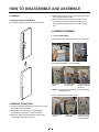
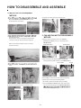
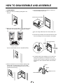
HOW TO DISASSEMBLE AND ASSEMBLE ....................................................................................................................... 93
DOOR ................................................................................................................................................................................. 93
HANDLE ............................................................................................................................................................................. 94
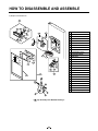
SHROUD, GRILLE FAN ..................................................................................................................................................... 94
ICEMAKER ......................................................................................................................................................................... 94
WATER VALVE DISASSEMBLY METHOD ........................................................................................................................ 95
FAN and FAN MOTOR DISASSEMBLY METHOD............................................................................................................. 95
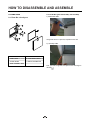
DISPENSER ....................................................................................................................................................................... 96
HOME BAR......................................................................................................................................................................... 98
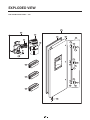
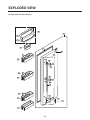
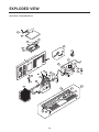
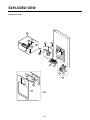
EXPLODED VIEW ................................................................................................................................................................ 99
-2-
WARNINGS AND PRECAUTIONS FOR SAFETY
8. Do not fray, damage, machine, heavily bend, pull out,
or twist the power cord.
Please observe the following safety precautions in order to
use safely and correctly the refrigerator and to prevent
accident and danger during repair.
9. Please check the evidence of moisture intrusion in the
electrical components. Replace the parts or mask it
with insulation tapes if moisture intrusion was
confirmed.
1. Be care of an electric shock. Disconnect power cord
from wall outlet and wait for more than three minutes
before replacing PWB parts. Shut off the power
whenever replacing and repairing electric components.
10. Do not touch the icemaker with hands or tools to
confirm the operation of geared motor.
2. When connecting power cord, please wait for more than
five minutes after power cord was disconnected from the
wall outlet.
11. Do not let the customers repair, disassemble, and
reconstruct the refrigerator for themselves. It may
cause accident, electric shock, or fire.
3. Please check if the power plug is pressed down by the
refrigerator against the wall. If the power plug was
damaged, it may cause fire or electric shock.
12. Do not store flammable materials such as ether,
benzene, alcohol, chemicals, gas, or medicine in the
refrigerator.
4. If the wall outlet is over loaded, it may cause fire. Please
use its own individual electrical outlet for the refrigerator.
13. Do not put flower vase, cup, cosmetics, chemicals,
etc., or container with full of water on the top of the
refrigerator.
5. Please make sure the outlet is properly earthed,
particularly in wet or damp area.
14. Do not put glass bottles with full of water into the
freezer. The contents shall freeze and break the glass
bottles.
6. Use standard electrical components when replacing
them.
7. Make sure the hook is correctly engaged.
Remove dust and foreign materials from the housing
and connecting parts.
15. When you scrap the refrigerator, please disconnect the
door gasket first and scrap it where children are not
accessible.
-3-
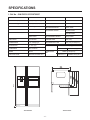
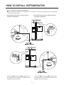
SPECIFICATIONS
1. Ref No. : GW-P227/L227/C227/B227
ITEMS
SPECIFICATIONS
ITEMS
SPECIFICATIONS
DIMENSIONS (mm)
894(W)X753(D)X1753(H)
FIRST DEFROST
4 - 5 Hours
NET WEIGHT (kg)
128(P227), 123(L227),119(B227),114(B227)
DEFROST CYCLE
13 - 15 Hours
COOLING SYSTEM
Fan Cooling
DEFROSTING DEVICE
Heater, Sheath
TEMPERATURE CONTROL
Micom Control
ANTI SWEAT HEATER
Dispenser Heater
DEFROSTING SYSTEM
Full Automatic
Home Bar Heater
Heater Defrost
ANTI-FREEZING HEATER
Damper Heater
INSULATION
Cyclo-Pentane
FREEZER LAMP
40W (1 EA)
COMPRESSOR
P.T.C. Starting Type
REFRIGERATOR LAMP
40W (1 EA) or 40W (2 EA)
EVAPORATOR
Fin Tube Type
REFRIGERANT
R134a (180g)
CONDENSER
Wire Condenser
DRIER
ID 0.83
CAPILLARY TUBE
MOLECULAR SIEVE XH-7
GW-P227***V
FREOL @ 10G (310 cc)
GW-P227***V
HTS55MT 10CST (190 cc)
1753
LUBRICATING
OIL
R600a (78g)
<Front View>
<Plane View>
-4-
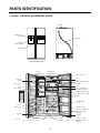
PARTS IDENTIFICATION
1. Ref No. : GW-P227/L227(INTERNAL FILTER)
Cover PWB
Dispenser Cover
Assembly
Water Tube
Ice & Water
Dispenser Button
Home Bar
*L227: Non Home bar
Freezer
Compartment
Refrigerator
Compartment
Milk product corner
Lamp
Shelf
Wine holder (Plastic or wire)
Door Rack
Automatic
Icemaker
Shelf or Drawer
Shelf
Can Server (Optional)
Snack drawer (Optional)
Lamp
Shelf or Drawer
Shelf (Folding or Normal)
Refreshment center (Optional)
Egg Box
Vegetable Drawer
(1 or 2)
Drawer
Door rack
Humidity switch
Drawer (2 or 3)
Miracle Zone (Optional)
Fresh compartment
(Optional)
Door Rack
Door rack
Conversion switch
(Meats/Vegetables)
(Optional)
Lower cover
-5-
PARTS IDENTIFICATION
2. Ref No. : GW-P227/L227(EXTERNAL FILTER)
Cover PWB
Dispenser Cover
Assembly
Ice & Water
Dispenser Button
Home Bar
*L227: Non Home bar
Freezer
Compartment
Refrigerator
Compartment
Milk product corner
Lamp
Shelf
Wine holder (Plastic or wire)
Door Rack
Automatic
Icemaker
Shelf or Drawer
Shelf
Can Server (Optional)
Snack drawer (Optional)
Lamp
Shelf or Drawer
Shelf (Folding or Normal)
Refreshment center (Optional)
Egg Box
Vegetable Drawer
(1 or 2)
Drawer
Door rack
Humidity switch
Drawer (2 or 3)
Miracle Zone (Optional)
Fresh compartment
(Optional)
Door Rack
Door rack
Conversion switch
(Meats/Vegetables)
(Optional)
Lower cover
-6-
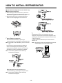
HOW TO INSTALL REFRIGERATOR
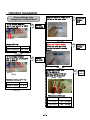
1. How to Adjust Door Height of Refrigerator
■ Make the refrigerator level first. (If the refrigerator is not installed on the flat floor, the height of freezer and refrigerator
door may not be the same.)
1. If the height of freezer door is lower than that of
refrigerator compartment :
2. If the height of freezer door is higher than that of
refrigerator compartment :
Insert a driver B into the groove A of adjusting screw
and rotate driver in arrow direction (clockwise) until the
refrigerator becomes horizontal.
Insert a driver B into the groove A of adjusting screw
and rotate driver in arrow direction (clockwise) until the
refrigerator becomes horizontal.
-8-
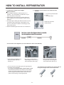
HOW TO INSTALL REFRIGERATOR
2. Connection to Main Water Supply
2-1. Check all correct items (In case of External Filter
Models).
Before Installation
1. The icemaker requires the water pressure of 1.5 8.5kgf/cm2. (It is acceptable if city water fills a cup of
180cc with water for 3 seconds)
2. Install booster pump where the city water pressure is
below 1.5kgf/cm2 for normal operation of water and ice
dispenser.
3. The total length of water pipe shall be less than 12m. Do
not bend the pipe at right angle. If the length is more
than 12m, there will be troubles on water supply due to
water pressure drop.
4. Please install water pipe where there is no heat around.
1 x Connector type Water Filter
2 x Clips
1 x 8mm Water Pipe
Plastic Pipe Connector
Rubber Washer
2-2. Connection to the Appliance (In case of External or Internal Filter Models).
At the back of the appliance you
will see the water inlet valve.
(See Fig. A)
Unscrew the metal thearded
collar and place it over one end
of the water pipe. (See Fig. B)
You now need to cut the water pipe to the right lenght for
connection of the water filter.
It is suggested that approximately 1.5mm of pipe is used
- this should allow the filter to be located in an accessible
position (for periodic replacement) and also allow some
slack in the pipe behind the machine so that it con be
pulled out for cleaning or servicing purposes.
-9-
Firmly push the water pipe onto
the water inlet valve and tighten
up the metal collar. (See Fig. C)
You must also ensure that the cut is square and not
at any sort of angle as this could cause a leak.
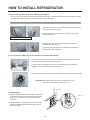
HOW TO INSTALL REFRIGERATOR
2-3. Connection of Water Filter (In case of External Filter Models).
Now you have cut the pipe from the back of the appliance to lenght. It needs to be attached to the water filter. The filter
is marked with with the direction of the water flow (i.e. from tap to fridge).
Remember however that the connection is being done from the refrigerator to the tap (i.e. the reverse of the water flow when in use).
Just insert tube into the end of the filter that the flow arrow points
until the tube stop. (See Fig. E)
After inserting tube, put together the clip strongly. The clip fix
the tube. (See Fig. F)
Note the direction markings on the filter!
Repeat on the other end of the filter using the remainder of
the water pipe. (See Fig. H)
If you have connector type filter, put together the clip strongly.
The clip fix the tube. (See Fig. I)
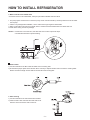
2-4. Connection to the Water Tap (In case of External and Internal Filter Models).
Cut the pipe that is connected to the water filter to the correct lenght. Again, make
sure that the cut is nice and square to avoid leaks.
Push the pipe into the smaller hole of the connector supplied in the plumbing
adapter kit. The pipe should be held firm. (See Fig. J)
Place the rubber washer inside the threaded tap connector and screw onto water tap.
CAUTION: feed pipe should be connected to cold water line. If it’s
connected to hot water line, trouble may occur.
Water Tube
2-5. Water Supply
1) After the installation of feed water, plug the refrigerator
to the earthered wall outlet, press the water dispenser
button for 2 - 3 minutes, and confirm that the water
comes out.
Water Tube
Nut
2) Check leakage at connecting part, then arrange water
tube and locate the refrigerator at its regular place if
there is no leaking.
- 10 -
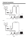
HOW TO INSTALL REFRIGERATOR
3. When customer uses bottled water.
*If customer wants to use bottled water, extra pump should be installed as shown below.
1. The pump system should not be on the floor (it may cause noise and vibration). Securely fasten the inlet and outlet
nuts of pump.
2. If there is any leakage after installation, cut the water tube at right angle and reassemble.
3. When put the water tube end into the bottle, leave a clearance between bottle bottom and water tube end.
4 Check water coming out and any leakage.
Caution : • If feed tube is more than 4m, less water will come out due to pressure drops.
• Use standard feed tube to prevent leaking.
Outternal Filter
1. Filter Fixation
1) Connect feed tube to the filter outlet and water valve connecting tube.
2) Fix the filter at proper place around the sink where it is easy to replace the filter and to receive the cleaning water.
Please consider the length of tube shall be less than 8m when locating filter.
2. Filter Cleaning
1) Connect feed tube to the inlet of feed valve and filter.
2) Clean the main valve and feed valve with water for at
least one minute until clean water comes out.
- 11 -
HOW TO INSTALL REFRIGERATOR
■ Install Water Filter (Applicable to some models only)
■ Before Installing water filter
1. Before installing the filter, take out the top shelf of the
refrigerator after tilting it to the direction (a) and lifting it
to the direction (b) and move it to the lower part.
2. Remove the lamp cover by pressing the protrusion
under the cover and pulling the cover to the front.
Control box
Aligning with the guide line
and the fastening indication line
Control box
Aligning with the guide line
and the loosening indication line
■ Installing water filter
1. Initial installation of water filter
Remove the filter substitute cap by turning it
counterclockwise (a) by 90 degrees and pulling it down.
■ After installing water filter
Reassemble the lamp cover and the top shelf of the
refrigerator. To place the top shelf of the refrigerator, raise
the front part of the shelf a bit so that the hook of the shelf
is fit into the groove.
In order to clean the water filter system, drain water for
about 3 min.
Note : Keep it safe to use it later when you do not use the
filter.
Note : Then open the door of the refrigerator and check for
water droppings on the shelf under the filter.
Remove the red cap from the filter and attach the
sticker. Insert the upper part of the filter (a) after
aligning with the guideline marked on the control box,
and fasten it by turning it clockwise by 90 degrees.
Note : Check that the guideline and the fastening
indication line are aligned.
Separation
of red cap
Substitute
cap
Adhesion
sticker
2. Replacement of water filter
While holding the lower part of the filter, turn it
counterclockwise (a) by 90 degrees and pull it down.
Note : Check that the guideline and the loosening
indication line are aligned.
- 12 -
HOW TO INSTALL REFRIGERATOR
3. How to Control the Amount of Water Supplied to Icemaker.
3-1. Confirm the amount of water supplied to the icemaker.
1. Remove the cover bucket : Lift the cover with a slight twisting.
2. Remove the ice bucket : Lift the lower part slightly and take the ice bucket out slowly.
• Caution : • Do not put your hands or tools into the
chute to confirm the operation of geared
motor. It may damage refrigerator or hurt
your hands.
• Check the operation of motor with its operation
noise.
3. Apply electricity after connecting water pipe.
1) Press test switch under the icemaker for two seconds as shown below.
2) The bell rings(ding~dong) and ice tray rotates and water comes out from the icemaker water tube.
3) The water shall be supplied two or three times into the tray. The amount of water supplied for each time is small.
Put a water container under the ice tray and press test switch.
4) When ice tray rotates, the water in it will spill. Collect the spilt water and throw away into the sink.
5) When ice tray has finished rotation, water comes out from the water tube. Confirm the amounts of water in the ice tray.
(refer to fig. The optimum amount of water is 80cc)
Confirm the amount
of water(Recommend:
the water should
not be over this
maximum level line).
Ice maker
Test Switch
* It is acceptable if the adjusted level of water is a bit smaller than maximum level.
- 13 -
HOW TO INSTALL REFRIGERATOR
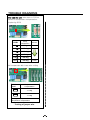
3-2. Control the amount of water supplied to the icemaker.
Caution : • Please unplug the power cord from the wall outlet and wait for more than three minutes before disconnecting
PCB cover as 310V is applied in the control panel.
(+) Driver
1. Disconnect PCB cover from the upper part of the refrigerator.
2. Adjust the amount of water supplied by using DIP switch.
Water Supplying Time Control Option
No
DIP SWITCH SETTING
WATER SUPPLY
TIME
REMARKS
S1
S2
S3
1
OFF
OFF
OFF
6.5 SEC
2
ON
OFF
OFF
5.5 SEC
3
OFF
ON
OFF
6 SEC
* The quantity of water supplied depends
on DIP switch setting conditions and
water pressure as it is a direct tap water
connection type. (the water supplied is
generally 60 cc to 100 cc)
4
ON
ON
OFF
7 SEC
* DIP switch is on the main PCB.
5
OFF
OFF
ON
7.5 SEC
6
ON
OFF
ON
8 SEC
7
OFF
ON
ON
9 SEC
8
ON
ON
ON
10 SEC
1) The water supplying time is set at 4.5 seconds when the refrigerator is delivered.
2) The amount of water supplied depends on the setting time and water pressure (city water pressure).
3) If ice cube is too small, increase the water supplying time. This happens when too small water is supplied into the ice tray.
4) If ice cube sticks together, decrease the water supplying time. This happens when too much water is supplied into the ice tray.
Caution : When adjusting the amount of water supplied, adjust step by step. Otherwise the water may spill over.
3. When adjustment of control switch for the amount of water supplied is complete, check the level of water in the ice tray.
Confirm the amount
of water(Recommend:
the water should
not be over this
maximum level line).
Switch ON
Switch OFF
- 14 -
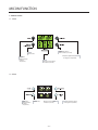
MICOM FUNCTION
1. Monitor Panel
1-1. LCD88
Light ON /OFF button /
Filter reset button (3 seconds)
Express freezer.
Temperature adjustment button
for refrigerator compartment.
Temperature
adjustment button
for freezer
compartment.
Dispenser selection button
Lock button (3 seconds)
1-2. LED88
Temperature
adjustment button
for freezer
compartment.
Express freezer.
Dispenser selection button
Lock button (3 seconds)
- 15 -
Temperature adjustment button
for refrigerator compartment.
MICOM FUNCTION
1-3. Display Second Function
1. Buzzer sound mute Mode
The buzzer sound is set to OFF.
It activates by sounding the recognition sound of “Ding~” after pressing and holding “Express FRZ” button more than 5
seconds. It inactivates when resetting the mode power.
2. Display Power saving Mode
It places display in standby mode until door is opened.
Press “Freezer” and “Express FRZ” buttons simultaneously to turn all leds become ON and then OFF with the recognition
sound of “Ding~” after 5 seconds. (Be sure not to press only one button to work.)
Once the mode activates, the display is always OFF. Until door is opened or display button is pressed. When 30 seconds
has elapsed after closing door or pressing button, the display turns OFF. To deactivate this mode is same as the
activation methods. The mode inactivates when resetting the power.
3. Exhibition Mode
This function is available when exhibiting a refrigerator in the shopping mall.
Function is inserted with recognition sound “Ding ~” if opening the refrigerator or freezer door and pressing both the
“Express FRZ” button and the “REFRIGERATOR” button at the same time for more than 5 seconds. If function is inserted,
all basic refreezing functions at the R/F room and the Storage room (COMP, F-FAN, C-FAN) turns off and the display
normally operates. However, the dispenser function normally operates.
The DEMO stops if pressing the button during DISPLAY DEMO, DEMO stops and the display normally operates but
performs DEMO operation again if not pressing the button again for more than 30 seconds (DEMO: Display scenario
when using the display).
Release method is same as input method.
The mode is released if power is reset.
- 16 -
MICOM FUNCTION
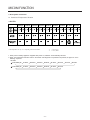
2. Description of Function
2-1. Funnction of Temperature Selection
< 88-LED >
Division
Power
Initially On
Change Type-1
of
Indication (88-LED) -19 ¡C
Lamp
1st Press
2nd Press
3rd Press
4th Press
5th Press
6th Press
7th Press
8th Press
3 ¡C -20 ¡C 2 ¡C -21 ¡C 1 ¡C -22 ¡C 0 ¡C -23 ¡C 6 ¡C -15 ¡C 5 ¡C -16 ¡C 4 ¡C -17 ¡C 3 ¡C -18 ¡C 2 ¡C
Freezer
Control
-19 ¡C
-20 ¡C
-21 ¡C
-22 ¡C
-23 ¡C
-15 ¡C
-16 ¡C
-17 ¡C
-18 ¡C
Refrigeration
Control
3 ¡C
2 ¡C
1 ¡C
0 ¡C
6 ¡C
5 ¡C
4 ¡C
3 ¡C
(Power
Initially
ON)
2 ¡C
(1 st Press)
* The temperature can vary ±3 °C depending on the load condition.
*(
*<
) : P227, L227
> : C227, B227
1. When power is initially applied or reapplied after power cut, “Medium” is automatically selected.
2. When the temperature selection switch in the freezer and refrigerator compartments is pressed, the light is on in the
following sequence:
< 88 - LED >
F Power Initially On
1st Press
2nd Press
3rd Press
4th Press
5th Press
6th Press
R Power Initially On
1st Press
2nd Press
3rd Press
4th Press
5th Press
6th Press
- 17 -
7th Press
8th Press
MICOM FUNCTION
2-2. Automatic ice maker
• The automatic ice maker can automatically make 6 pieces of ice cube at a time, 50~60 pieces a day. But these quantities
may be varied according to various conditions including how many times the refrigerator door opens and closes.
• Ice making stops when the ice storage bin is full.
• If you don’t want to use automatic ice-maker, change the ice-maker switch to ON-OFF.
If you want to use automatic ice-maker again, change the switch to OFF-ON.
NOTE : It is normal that a noise is produced when ice made is dropped into the ice storage bin.
2-3. When ice maker does not operate smoothly
Ice is lumped together
• When ice is lumped together, take the ice lumps out of the ice storage bin, break them into small pieces, and then place
them into the ice storage bin again.
• When the ice maker produces too small or lumped together ice, the amount of water supplied to the ice maker need to be
adjusted. Contact the service center.
✻ If ice is not used frequently, it may lump together.
Power failure
• Ice may drop into the freezer compartment. Take the ice storage bin out and discard all the ice then dry it and place it
back. After the machine is powered again, crushed ice will be automatically selected.
The unit is newly installed
• It takes about 12 hours for a newly installed refrigerator to make ice in the freezer compartment.
2-4. Express freezing
1. Express freezing is function to improve cooling speed of the freezing room by consecutively operating compressors and
freezing room fan.
2. Express freezing is released if power failure occurs and then returns to the original status.
3. Temperature setting is not changed even if selecting the express freezing.
4. The change of temperature setting at the freezing room or the cold storage room is allowed with express freezing
selected and prrocessed.
5. The cold storage room operates the status currently set with Express freezing selected and procesed.
6. If selecting the Express freezing, the Express freezing function is released after continuously operating compressor and
freezing room fan.
7. If frost removal starting time is arrived during Express freezing, Express freezing operation is done only for the remaining
time after completion of frost removal when the Express freezing operation time passes 90 minutes. If passing 90
minutes, Express freezing operation is done only for 2 hours after completion of frost removal.
8. If pressing Express freezing button during frost removal, the Express freezing LED is turned on but if pressing the
Express freezing, compressor operates after the remaining time has passed.
9. If selection Express freezing within 7 minutes (delay for 7 minutes of compressor) after the compressor stops,
compressor operates after the remaining time has passed.
10. The freezing room fan motor operates at the high speed of RPM during operation of Express freezing.
- 18 -
MICOM FUNCTION
2-5. Control of variable type of freezing room fan
1. To increase cooling speed and load response speed, MICOM variably controls freezing room fan motor at the high speed
of RPM and standard RPM.
2. MICOM only operates in the input of initial power or special freezing operation or load response operation for the high
speed of RPM and operates in the standard RPM in other general operation.
3. If opening doors of freezing / cold storage room or home bar while fan motor in the freezing room operates, the freezing
room fan motor normally operates (If being operated in the high speed of RPM, it converts operation to the standard
RPM). However, if opening doors of freezing room or home bar, the freezing room fan motor stops.
4. As for monitoring of BLDC fan motor error in the freezing room, MICOM immediately stops the fan motor by determining
that the BLDC fan motor is locked or poor if there would be position signal for more than 65 seconds at the BLDC motor.
Then it displays failure (refer to failure diagnosis function table) at the display part of refrigerator, performs re-operation in
the cycle of 30 minutes. If normal operation is performed, poor status is released and refrigerator returns to the initial
status (reset).
2-6. Control of M/C room fan motor
1. The M/C room fan motor performs ON/OFF control by linking with the COMP.
2. It controls at the single RPM without varying RPM.
3. Failure sensing method is same as in fan motor of freezing fan motor (refer to failure diagnosis function table for failure
display).
2-7. Door opening alarm
1. Buzzer generates alarm sound if doors are not closed even when more than a minute consecutively has passed with
doors of freezing / cold storage room or home bar opened.
2. Buzzer rings three times in the interval of 0.5 second after the first one-minute has passed after doors are opened and
then repeats three times of On/Off alarm in the cycle of every 30 seconds.
3. If all the doors of freezing / cold storage room or home bar are closed during door open alarm, alarm is immediately
released.
Doors of freezing /
cold storage room Closing Opening Closing
or home bar
Opening
Closing
3 Times 3 Times 3 Times 3 Times
BUZZER
Within
a minute
A minute
30
30
30
seconds seconds seconds
2-8. Ringing of button selection buzzer
1. If pressing the front display button, “Ding ~ “ sound rings.
2-9. Ringing of compulsory operation, compulsory frost removal buzzer
1. If pressing the test button in the main PCB, “Phi ~ “ sound rings.
2. In selecting compulsory operation, alarm sound is repeated and completed in the cycle of On for 0.2 second and Off for
1.8 second three times.
3. In selecting compulsory frost removal, alarm sound is repeated and completed in the cycle of On for 0.2 second , Off for
0.2 second, On for 0.2 second and Off for 1.4 second three times.
- 19 -
MICOM FUNCTION
2-10. Frost removal function
1. Frost removal is performed whenever total operation time of compressor becomes 7 ~ 7.5 hour.
2. In providing initial power (or returning power failure), frost removal starts whenever total operation time of compressor
becomes 4 ~ 4.5 hour.
3. Frost removal is completed if temperature of a frost removal sensor becomes more than 5°C after starting frost removal.
Poor frost removal is not displaced if it does not arrive at 5°C even if two hours have passed after starting frost removal.
4. No removal is done if frost removal sensor becomes poor (snapping or short-circuit).
2-11. Sequential operation of built-in product
Built-in products such as compressor, frost removal heater, freezing room fan, Cooling Fan and step motor damper are
sequentially operated as follows for preventing noise and part damage occurred due to simultaneous operation of a lot of
parts in applying initial power and completing test.
Function
When temperature
of a frost removal
sensor becomes
more than 45°C
(In purchase,
movement)
In applying Initial power
When
temperature of a
frost removal
sensor becomes
less than 45°C
(In power failure,
service)
Load Operation Sequence
POWER
ON
0.3
sec.
F-FAN
&
C-FAN
ON
0.3
sec.
R-STEP
MOTOR
DAMPER
ON
MIRACLE
ZONE
0.3
STEP
sec.
DAMPER
MOTOR
ON
0.3
sec.
HOME
BAR
HEATER
ON
If error occurs
during operation,
initial operation is
not done.
■ Sequence of
ON
DISP'
HEATER
ON
TEST MODE
Test mode 2
(Compulsory frost
removal)
COMP
ON
0.3
POWER sec.
0.3 PIPE
&
sec.
Test mode 1
(Compulsory
function)
0.3
sec.
Remark
TEST
S/W
(PRESS
Once)
TEST
S/W
(PRESS
2 Times)
6
sec.
FROST
REMOVAL
HEATER
ON
5
sec.
FROST
REMOVAL
HEATER
OFF
0.3
sec.
HOME
BAR
HEATER
ON
5
sec. HOME
BAR
HEATER
OFF
0.3
sec.
DAMPER 5 DAMPER
sec.
&
&
DUCT DOOR
DUCT DOOR
HEATER
HEATER
ON
OFF
load operation
when closing
F-room and
R-room.
MIRACLE
PIPE 0.3
0.3
0.3
0.3 ZONE 0.3
&
sec. COMP sec. F-FAN sec. R-STEP sec.
sec. HOME
STEP
&
BAR
MOTOR
DISP'
DAMPER
C-FAN
HEATER
DAMPER
HEATER
ON
MOTOR
ON
ON
ON
OFF
ON
OTHER
LOAD
0.3
sec.
COMP
0.3
sec.
ON
OFF
COMP
OFF
0.3
sec.
F-FAN
&
C-FAN
OFF
- 20 -
F-FAN
&
C-FAN
ON
0.3
sec.
0.3
sec.
R-STEP
MOTOR
DAMPER
ON
FROST
REMOVAL
HEATER
ON
0.3
sec.
0.3
sec.
MIRACLE
ZONE
STEP
DAMPER
MOTOR
CLOSE
R-STEP
MOTOR
DAMPER
CLOSE
If pressing switch
once more in the
test mode 2 or
temperature of a
frost removal
sensor is more
than 5°C, it
immediately
returns to the test
mode for initial
operation
(COMP operates
after 7 minutes).
MICOM
Error
Code
TROUBLE
DIAGNOSIS
1-1. Error Code Summary
! WARNING
When you check the Resistance values, be sure to turn off the power.
And wait for the voltage-discharge sufficiently.
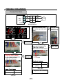
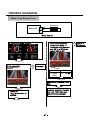
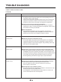
TROUBLE DIAGNOSIS
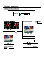
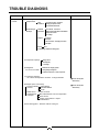
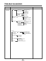
1-2. Troubleshooting With Error
Freezer Sensor Error
F-Sensor
CON7
Main PCB
1
2
white
white
Wiring diagram
Is it displayed under picture?
Disconnect CON7and
measure the value. Is
resistance value between
pins 1 & 2 of CON7 as
below? (WH to WH)
No
Replace
F-sensor
Yes
Is the connection loose?
(CON7)
Yes
Reconnect
Pin2
Pin1
Test Point
Result
Pin1 to pin2
1.4 ~ 120 ㏀
Yes
Reconnect CON7 and Power
ON
No
Power Off
Tip : To protection of
MICOM
If the same situation appears, Repla
ce the main PCB.
Otherwise, explain to the customer!
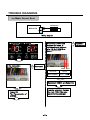
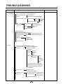
TROUBLE DIAGNOSIS
Refrigerator Sensor Error
R1-Sensor
CON8
Main PCB
5
6
white
white
Wiring diagram
Is it displayed under picture?
Disconnect CON8 and
measure the value. Is
resistance value between
pins 5 & 6 of CON8 as
below? (WH to WH)
No
Yes
Is the connection loose?
(CON8)
Yes Reconnect
Pin6 Pin5
Test Point
Result
Pin5 to Pin 6
6 ~ 300 ㏀
Yes
Reconnect CON8 and Power
ON
No
Power Off
Tip : To protection of
MICOM)
If the same situation appears, Repla
ce the main PCB.
Otherwise, explain to the customer!
Replace
R-sensor
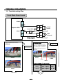
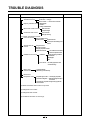
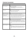
TROUBLE DIAGNOSIS
Defrost Sensor Error
D-Sensor
CON7
Main PCB
3
4
BO
BO
6
1
7
2
BO
BO
Housing-A
Wiring diagram
Is it displayed under picture?
Is resistance value between No
pins 1 & 2 of Housing- A as
below? (BO to BO)
Replace a
D-Sensor
Yes
Is the connection loose?
(CON7)
Yes
Pin2
Pin1
Reconnect
No
Power Off
Tip : To protection of MICOM
Test Point
Result
Pin1 to
pin2
1.156 ~
141.5 ㏀
Yes
Disconnect CON6 and
measure the value. Is
resistance value between
pins 3 & 4 of CON7 as
below? (BO to BO)
No
Replace
D_Sensor
Reconnect and Power ON
If the same situation appears, Repla
ce the main PCB.
Otherwise, explain to the customer!
Pin4 Pin3
Test Point
Result
Pin3 to Pin 4
6 ~ 300 ㏀
Yes
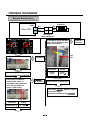
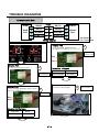
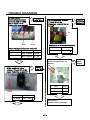
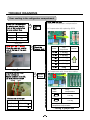
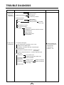
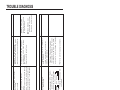
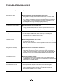
TROUBLE DIAGNOSIS
Defrost Heater Error
D-Sensor
BO
BO
1
6
2
7
BO
BO
Housing-A
3
4
5
Main
PCB
6
BN
8
2
9
1
BL/WH
BN
FUSE-M
BL
BK
DEF-Heater
1
CON7 CON3
BK
2
Wiring diagram
Enter the TEST 2 MODE
No
Is the voltage value
between pins 6(BL/WH) and
5 (BN) of CON3 230 V AC?
Is it displayed under picture?
Replace
MAIN PCB
Yes
Pin6 Pin5
Relay operation
Is the connection loose?
Yes
Reconnect
Test Point
Result
Pin5 To Pin6
230V
Yes
Enter the TEST 1 MODE
Is the voltage value
between pins 6(BL/WH) and
5 (BN) of CON3 0 V AC?
CON3
Pin6 Pin5
Relay Open
CON7
No
Test Point
Result
Pin5 To Pin6
0~2V
Yes
No
Replace
MAIN PCB
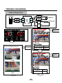
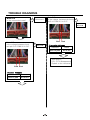
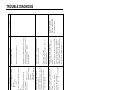
TROUBLE DIAGNOSIS
Is the resistance value
between pins 6(BL/WH) and
5 (BN) of CON3
like as below?
Pin6 Pin5
Resistance
No
Normal
Result
Pin5 To Pin6
180 ~ 230 Ω
Replace
Heater
No
(1) (2)
Heater Resistance
Pin1
Test Point
Is the resistance value
of heater like as
below?
Test Point
Result
(1) To (2)
180 ~ 230 Ω
Yes
Yes
Is the resistance value
No
of Fuse –M like
as below?
Reconnect
Is the resistance
value of DEF-sensor like No
as below? It depends on
the temperature.
Replace
DEF-sensor
(1) BL
(2) BN
(1) BO
(2) BO
Open or Short of Fuse-M
Test Point
Result
(1) To (2)
0~0.5 Ω
Yes
Defrost Sensor Resistance
Test Point
Result
Test Point
Result
-30℃
129.3 ㏀
10℃
19.53 ㏀
-20℃
76.96 ㏀
20℃
13.03 ㏀
-10℃
47.34 ㏀
30℃
8.896 ㏀
0℃
30 ㏀
40℃
6.201 ㏀
Yes
Explain to the customer!
: It can be occurred, when the gasket is not
stuck to product or when you put the high
temperature loads (hot foods) a lot
in the product.
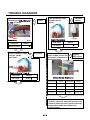
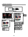
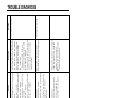
TROUBLE DIAGNOSIS
Freezer Fan Error
10
Main
PCB
12
11
CON7
PR
YL
BL
PR
5
1
4
2
3
3
RD
F-FAN
BK
Housing
Wiring diagram
Is it displayed under picture?
Does the cold-air come
N0
out of the top of the main
duct?
Check fan motor
(Connector,
Frozen, Locked)
Yes
Is the connection loose?
Yes
Reconnect
Yes
Is the feedback voltage bet
ween pin10 and pin11 of
No
CON7 like as below?
(from motor to main board)
No
Reset and
Enter the TEST 1 MODE
Is the output voltage betwe
en pin11 and pin12 of
CON6 like as below?
N0
Replace
MAIN PCB
Pin11
Pin10
Feedback Voltages
Pin12 Pin11
Test Point
Result
Pin10 To
pin11
1~4V
Yes
Freezer Fan Voltages
Test Point
Result
pin11 To pin12
Yes
12 ~ 16 V
Explain to the customer!
Replace
Main PCB
TROUBLE DIAGNOSIS
Condenser Fan Error
CON7
9
7
Main PWB
8
SB
GY
BN
1
1
2
2
3
3
PR
RD
C-FAN
BK
Housing
Wiring diagram
Is it displayed under picture?
Is the condenser fan
rotate?
N0
Check fan motor
(Connector,
Locked, mouse)
Yes
Is the connection loose?
Yes
Reconnect
Yes
Is the feedback voltage
between pin8and pin9 of
No
CON7 like as below?
(from motor to main board)
No
Reset and
Enter the TEST 1 MODE
Is the output voltage
between pin7 and pin8 of
CON6 like as below?
N0
Replace
MAIN PCB
Pin9 Pin8
Feedback Voltages
Test Point
Result
Pin8 To pin9
1~4V
Pin8 Pin7
Condenser Fan Voltages
Test Point
Result
pin7 To pin8
12 ~ 16 V
Yes
Yes
Explain to the customer!
Replace
Main PCB
TROUBLE DIAGNOSIS
Communication Error
Hinge
CON6
6
MAIN
PCB
5
4
3
RD(Rx)
BN(Tx)
BO(GND)
3
3
2
2
4
WH/BK(12V)
1
4
1
CON101
RD(Tx)
1
BN(Rx)
2
BO(GND)
DISPLAY
PCB
3
WH/BK(12V)
4
Rx: Receiver
Tx: Transmitter
Wiring diagram
Is Er-CO displayed?
Display PCB
Is the voltage between pin1
and pin3 of CON101 0 V or 5 V?
N0
Replace the
Display PCB
Pin3
Pin1
Yes
Display PCB
Is the connection loose?
Yes
Reconnect
Transmitter Voltages
Test Point
Result
pin1 To pin3
0 V or 5 V
Yes
No
Display PCB
Is the voltage between pins 2 and
pin 5 of CON101?
Is the joint connection
loose In the Hinge?
N0
Replace the
Display PCB
Pin3
Pin2
Receiver fail Voltages
Test Point
Result
pin2 To pin3
0 V or 5 V
Yes
No
Yes
Reconnect
TROUBLE DIAGNOSIS
MAIN PCB
Is the connection loose?
Yes
Reconnect
Main PCB
Is the voltage between pin4 and No
pin5 of CON6 0 V or 5 V?
Replace the
Main PCB
No
Main PCB
Is the voltage between pins 4
and pin 6 of CON6 0V or 5V?
Pin5 Pin4
No
Replace the
Main PCB
Transmitter Voltages
Test Point
Result
pin4 To pin5
0 V or 5 V
Yes
After plug in,
If Er-CO is disappeared,
Explain to the customer!
Pin6 Pin4
Receiver Voltages
Test Point
Result
pin4 To pin6
0 V or 5 V
Yes
TROUBLE DIAGNOSIS
Refrigerator2 Sensor Error
R2-Sensor
CON8
Main PCB
7
8
GY
GY
Wiring diagram
Is it displayed under picture?
Disconnect CON8 and
measure the value. Is
resistance value between
pins 7 & 8 of CON8 as
below? (GY to GY)
Yes
Is the connection
loose?(CON8)
Yes
Reconnect
Pin8 Pin7
Test Point
Result
Pin7 to pin8
6 ~ 300 ㏀
Yes
Reconnect CON8 and Power
ON
No
Power Off
Tip : To protection of
MICOM)
It can be occurred, Replace
the main PCB. Otherwise,
explain to the customer!
No
Replace a
R2-Sensor
TROUBLE DIAGNOSIS
Water Tank Sensor Error
WT-Sensor
CON6
Main PCB
10
9
GY
GY
Wiring diagram
Is it displayed under picture?
Disconnect CON6and
measure the value. Is
resistance value between
pins 9& 10 of CON6 as
below? (GY to GY)
Yes
Is the connection
loose?((CON6)
Yes
Reconnect
Pin10 Pin9
Test Point
Result
Pin9 to
pin10
6 ~ 300 ㏀
Yes
Reconnect CON5and Power
ON
No
Power Off
Tip : To protection of
MICOM)
It can be occurred, Replace
the main PCB. Otherwise,
explain to the customer!
No Replace a
WT-Sensor
TROUBLE DIAGNOSIS
Ice Maker Sensor Error
ICE-Sensor
CON10
Main PCB
GY
2
GY
1
Wiring diagram
Is it displayed under picture?
Disconnect CON10 and
measure the value. Is
resistance value between
pins 1 & 2 of CON10 as
below? (GY to GY)
No
Yes
Is the connection
loose?(CON10)
Yes
Reconnect
Pin2 Pin1
Test Point
Result
Pin1 to pin2
1.4 ~ 120㏀
Yes
Reconnect CON10 and Power ON
No
Power Off
Tip : To protection of
MICOM)
It can be occurred, Replace
the main PCB. Otherwise,
explain to the customer!
Replace a
ICE-Sensor
TROUBLE DIAGNOSIS
Ice Maker KIT Error
CON10
Main PCB
10
9
Motor
RD
V
WH
Wiring diagram
Is it displayed under picture?
Inspection Ice Maker
module part in freezer
room.
Yes
Is the connection
loose?(CON10)
Yes
Reconnect
No
explain to the customer!
No
Is the voltage between
pins 9 and pin 10 of
CON10 5V ~ 12V?
Pin10Pin9
Motor Receiver Voltages
Test Point
Result
pin9 To
pin10
5-12 V
Yes
N0
Replace the
Main PCB
Yes
Replace
ICE Maker
Unit
TROUBLE DIAGNOSIS
1-3. Troubleshooting Else
Crush Mode Doesn’t work
CON3
7
SB
11 SB
Dispenser PCB
Lever S/W
CON5
1
WH
4
1
2
2
BL
3
2
5
1
Wiring diagram
Is the connection loose?
(CON3,4)
Yes
Reconnect
CON4
Auger
Motor
Housing-B
BL
DISP
S
Solenoid
RD
Housing-C
5
V
Housing-C
In Crush Mode,
Is the voltage between
pin2 of CON5 and pin11
of CON3 like as below,
while pushing the lever
switch?
CON5
No
Replace
Main PCB
CON3
Pin1
Pin11
Output voltage of auger motor
CON3
No
Level switch
Test Point
Result
Pushing
pin1 To pin11
230 V
Normal
pin1 To pin11
0 ~ 2V
Yes
TROUBLE DIAGNOSIS
In Crush Mode,
No
Is the voltage between
pin1 and pin5 of CON5
like as below, while
pushing the lever switch?
Replace
Main PCB
Is the resistance between
(1) and (2) of the
Dispenser solenoid like as
below?
No
Replace
Dispenser
Solenoid
(1)
(2)
Pin1
Pin5
Resistance of Dispenser solenoid
Output voltage of dispenser solenoid
Level switch
Test Point
Result
Pushing
pin1 To pin5
230 V
Normal
pin1 To pin5
0 ~ 2V
Result
(1) To (2)
283 ~328 Ω
Yes
Is the condition of
the micro switch like as
below?
Yes
Is the resistance value
between (1) and (2) of the
Auger motor like as below?
No
(1)(2)
Test Point
Result
(1) To (2)
12.3 ~ 15.1 Ω
Yes
Test Point
Replace
Auger Motor
(1)
(2)
Status
Tester
Normal
Infinity
Push the Lever
0Ω
Yes
After plug in,
explain to the customer!
No
Replace
Micro
Switch
TROUBLE DIAGNOSIS
CUBE Mode doesn’t work
Housing-A
WH
PR
CON3
3
10
11 SB
Dispenser PCB
1
WH
2
1
4
1
2
Lever S/W
CON5
2
2
Housing-C
5
3
2
5
1
Wiring diagram
Is the connection loose?
Yes
Reconnect
BL
SB
BL
S
CUBE
Solenoid
V
Auger
Motor
Housing-B
BL
DISP
S
Solenoid
RD
Housing-C
In CUBE Mode,
Is the voltage between
pin2 of CON5 and pin10
of CON3 like as below,
while pushing the lever
switch?
No
Replace
Main PCB
CON4
CON5
CON3
Pin1
Pin10
Relay open of cube solenoid
CON3
Level switch
Test Point
Result
Pushing
pin1 To pin10
230 V
Normal
pin1 To pin10
0 ~ 2V
No
Yes
TROUBLE DIAGNOSIS
In Crush Mode,
Is the voltage between
pin2 of CON5 and pin11
of CON3 like as below,
while pushing the lever
switch?
CON5
Replace
Main PCB
No
Is the resistance value
between (1) and (2) of the
Auger motor like as below?
No
Replace
Auger Motor
(1)
(2)
CON3
Pin1
Pin11
Resistance of Auger Motor at 25℃
Output voltage of auger motor
Level switch
Test Point
Result
Pushing
pin1 To pin11
230 V
Normal
pin1 To pin11
0 ~ 2V
Yes
In Crush Mode,
No
Is the voltage between
pin1 and pin5 of CON5
like as below, while
pushing the lever switch?
Replace
Main PCB
Test Point
Result
(1) To (2)
12.3 ~ 20.1 Ω
Yes
Is the resistance value
between (1) and (2) of the
Cube solenoid like as
below?
No
Replace
Cube
Solenoid
(1)
(2)
Resistance of Cube solenoid
Pin5
Pin1
Output voltage of dispenser solenoid
Level switch
Test Point
Result
Pushing
pin1 To pin5
230 V
Normal
pin1 To pin5
0 ~ 2V
Yes
Test Point
Result
(1) To (2)
156.8 ~ 173.3 Ω
Yes
TROUBLE DIAGNOSIS
Is the resistance between
(1) and (2) of the
Dispenser solenoid like as
below?
No
Replace
Dispenser
Solenoid
(1)
(2)
Resistance of Dispenser solenoid
Test Point
Result
(1) To (2)
283 ~328 Ω
Yes
Is the condition of
the micro switch like as
below?
(1)
(2)
Status
Tester
Normal
Infinity
Push the Lever
0Ω
Yes
After plug in,
explain to the customer!
No
Replace
Micro
Switch
TROUBLE DIAGNOSIS
Water Mode Doesn’t work
Main
1
PCB
CON5
WH
Lever S/W
1
1
6
2
V
PILOT Valve
V
Water Valve
Housing-A
Main
PCB
7
PK
8
CON3
3
1
5
2
Housing-B
BK
Wiring diagram
Is the connection loose?
Yes
Reconnect
In Water Mode,
No
Is the voltage between
pin1 of CON5 and pin7 of
CON3 like as below, while
pushing the lever switch?
Replace
Main PCB
CON4
CON5
CON3
Pin1
Pin7
Output voltage of PILOT Valve
CON3
Level switch
Test Point
Result
Pushing
pin1 To pin7
230 V
Normal
pin1 To pin7
0 ~ 2V
No
Yes
TROUBLE DIAGNOSIS
In Water Mode,
No
Is the voltage between
pin1 of CON5 and pin8 of
CON3 like as below, while
pushing the lever switch?
CON5
Replace
Main PCB
CON3
Pin1
Pin8
Output voltage of Water Valve
Level switch
Test Point
Result
Pushing
pin1 To pin8
230 V
Normal
pin1 To pin8
0 ~ 2V
Yes
Water Valve
Is the resistance value of
Water Valve like as
below?
Replace
Water-valve
No
(1)
(2)
Ice Maker
Dispenser
Checking resistance of Water Valve
Test Point
Result
(1) To (2)
1.4 ~ 1.6 KΩ
Yes
After plug in,
explain to the customer!
TROUBLE DIAGNOSIS
Freezer-lamp Doesn’t work
BO
F-Lamp
12
RD
CON3
BL
5
Main PCB
6
2
CON7
RD
1
RD
2
F-DOOR Switch
RD
Housing
Wiring diagram
Is the condition of
No
the freezer door switch
like as below?
Replace
Door switch
Is the voltage between pin 5
and 6of CON7 like as
below?
No
Replace
Main PCB
(1)(2)
Pin6 Pin5
Voltage of Door switch
Status
Tester
Normal
0Ω
Push the Switch
Infinity
Test Point
Result
Closed
Pin5 To Pin6
5V
Open
Pin5 To Pin6
0V
Yes
Is the voltage between pin2
and pin12 of CON3 like as
below?
Yes
Is the connection
loose?(CON3/CON7)
Door
Yes
CON3
Replace
Main PCB
Reconnect
PIN12
PIN2
voltage of Freezer lamp
Door
Test Point
Result
Closed
Pin2 To Pin12
0~2V
Open
Pin2 To Pin12
230 V
Yes
CON7
No
No
Replace Lamp
TROUBLE DIAGNOSIS
Refrigerator-lamp Doesn’t work
Hinge
PR
1
BL
MAIN
PCB
4
BO
1
1
PK
3
3
H/BAR
DOOR S/W
BO
PK
122
2
CON4
R-Lamp
CON8
R-DOOR
S/W
Housing
Wiring diagram
Is the condition of
the Refrigerator door
switch like as below?
Replace
Door switch
No
Is the voltage between pin 3
and 4 of CON8 like as
below?
No
Replace
Main PCB
(1)(2)
Pin4 Pin3
Voltage of Door switch
Status
Tester
Normal
0Ω
Push the Switch
Infinity
Test Point
Result
Closed
Pin3 To Pin4
5V
Open
Pin3 To Pin4
0V
Yes
Is the voltage between pin 1
and pin3 of CON4 like as
below?
Yes
Is the connection
loose?(CON4/CON8)
Door
Yes
No
Replace
Main PCB
Reconnect
PIN3
PIN1
voltage of Refrigerator lamp
CON8
CON4
Door
Test Point
Result
Closed
Pin1 To Pin3
0~2V
Open
Pin1 To Pin3
230 V
Yes
No
Replace Lamp
TROUBLE DIAGNOSIS
Poor cooling in the
refrigerator compartment
Is the voltage between
pin 11 and pin 12 of CON7
like as below?
N0
Does the cold-air come out of
the top of the main duct?
Check the
Damper
itself
No
Replace
Main PCB
Pin12 Pin11
Yes
Voltage of F-fan
Test Point
Result
pin11 To pin12
12 ~ 16 V
Enter the TEST 1 MODE
Does not cold-air come
out of the top of the main
duct?
Yes
Check the
Damper
itself
Yes
Is the voltage between
pin 10 and pin 11 of CON7
like as below?
No
Replace
Main PCB
No
Checking Damper itself
Is the resistance
Values between (1) & (4),
(2) & (3) like as below?
Pin11
Pin10
(2)WH
(4)YL
Feedback voltage of F-fan
Test Point
Result
Pin10 To pin11
1~4V
Yes
(3)BL
(1)RD
Resistance of Damper
Test Point
Result
(1) To (4)
369 ~ 451 Ω
(2) To (3)
369 ~ 451 Ω
No
Replace
Damper
TROUBLE DIAGNOSIS
After reset the unit, take steps to PCB as
follows for temperature compensation.
1. replacing RCR1
RCR1
Temp.
Compension
Remark
10 ㏀
0 deg
Current
8.2 ㏀
- 0.5 deg
5.6 ㏀
- 1.0 deg
3.3 ㏀
-1.5 deg
2.0 ㏀
- 2.0 deg
470 Ω
- 2.5 deg
Colder
2. Compensate with Jump wire cutting
JUMP
WIRE
JCR3
JCR4
Temp.
Compensation
-1.0 deg
-1.0 deg
Cutting both jumpers affords a 2º
temperature compensation
* Cutting of jumper wire
TROUBLE DIAGNOSIS
Over cooling in the refrigerator compartment
Check the Fan operation
by placing your hand in
front of the vents to feel
for any cold air flow.
Door
Fan-Motor
Open
OFF
Closed
ON
After reset the unit, take steps to PCB as
follows for temperature compensation.
Yes
Replace
Fan
1. Compensate with replacing RCR1
No
Enter the TEST 1 MODE
Does the cold-air coming
out of the top of the main
duct.?
No
Check the
Damper itself
RCR1
Temp.
Compension
Remark
180 ㏀
+ 2.5 deg
Current
56 ㏀
+ 2.0 deg
33 ㏀
+ 1.5 deg
18 ㏀
+ 1.0 deg
12 ㏀
+ 0.5 deg
10 ㏀
0 deg
Colder
Yes
Checking Damper itself
Is the resistance
Values between (1) & (4),
(2) & (3) like as below?
(2)WH
2. Compensate with Jump wire cutting
No
Replace
Damper
(4)YL
JUMP
WIRE
(3)BL
(1)RD
JCR1
Temp.
Compensation
+1.0 deg
Resistance of Damper
Test Point
Result
(1) To (4)
369 ~ 451 Ω
(2) To (3)
369 ~ 451 Ω
JCR2
+1.0 deg
Cutting both jumpers affords a 2º
temperature compensation
* Cutting of jumper wire
TROUBLE DIAGNOSIS
1. How To Remove Terminal Position
Assurance (TPA)
* AC TPA
3. How To Start Test Mode
Push the TEST button on the Main PWB,
You can start the TEST MODE.
TEST BUTTON
* DC TPA
After measure the values,
you should put in the TPA again
*1 time : Comp / Damper / All FAN on,
(All things displayed)
2. Wire Color
BL: Blue
WH: White
BO: Bright Orange
BK: Black
BN: Brown
PR: Purple
RD: Red
GN: Green
SB: Sky Blue
GY: Gray
* 2 times : Damper closed
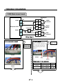
ICE MAKER AND DISPENSER WORKING PRINCIPLES AND REPAIR
1. Working Principles
1-1. Ice Maker Working Principles
Power Input
Initial Control
• Level Ice Maker Cube Mould for “Initial Control”
after power is input.
Ice Making Control
• Wait until the water in the cube mould is frozen
after ice maker starts operation.
Ice Ejection Control
• Check ice bucket is full of ice by rotating ice ejection
motor in normal and reverse direction and eject ice into
the ice bucket if ice bucket is not full.
Water Supply Control
• Conduct “Ice Making Control” after supplying water into the ice maker
cube mould by operating water valve.
Test Control
• This is for refrigerator assembly line and service. When “ice making test switch” is pressed,
it operates in the following steps: initial ice ejection water supply control steps.
1-2. Dispenser Working Principles
1. This function is available in Model GW-P227, GW-L227 where water and ice are available without opening freezer
compartment door.
2. “Crushed Ice” is automatically selected when power is initially applied or reapplied after power cut.
3. When dispenser selection switch is continuously pressed, light is on in the following sequence:
“Water” → “Cube Ice” → “Crushed Ice” .
4. Lamp is on when dispenser button is pressed.
5. In case of crushed ice mode, when dispenser button is pressed, dispenser solenoid and geared motor work so that
crushed ice can be dispensed if there is ice in the ice bank.
6. In case of cubed ice mode, when dispenser button is pressed, cube ice solenoid and geared motor work so that cube ice
can be dispensed if there is ice in the ice bank.
7. In case of water mode, when dispenser button is pressed, water valve opens and water is supplied if water valve is
normally installed on the right side of the machine room.
8. Ice and water are not available when freezer door is open.
- 24 -
ICE MAKER AND DISPENSER WORKING PRINCIPLES AND REPAIR
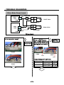
2. Function of Ice Maker
2-1. Initial Control Function
1. When power is initially applied or reapplied after power cut, it detects level of ice maker cube mould after completion of
MICOM initialization. The detecting lever moves up and down.
2. The level of ice maker cube mould is judged by output signal, high and low signal, of Hall IC. Make the cube mould to be
horizontal by rotating ice ejection motor in normal or reverse direction so that High/Low signal can be applied to MICOM
Pin No. 42.(bar LED: Pin NO. 46)
3. If there is no change in signals one minute after the geared motor starts to operate, it stops icemaker operation and check
the signal every hour. It resets initialization of icemaker when it becomes normal.
4. It judges that the initial control is completed when it judges the ice maker cube mould is horizontal.
5. Ice ejection conducts for 1 cycle irrespect of ice in the ice bucket when power is initially applied.
2-2. Water Supply Control Function
1. This is to supply water into the ice maker cube mould by operating water valve in the machine room when ice ejection
control is completed and ice maker mould is even.
2. The quantity of water supplied is determined by DIP switch and time.
<Water Supply Quantity Table>
DIP SWITCH SETTING
No
WATER SUPPLY
TIME
REMARKS
S1
S2
1
OFF
OFF
4.5 SEC
2
ON
OFF
4.0 SEC
3
OFF
ON
5.5 SEC
* The quantity of water supplied depends
on DIP switch setting conditions and
water pressure as it is a direct tap water
connection type. (the water supplied is
generally 60 cc to 100 cc)
4
ON
ON
6.5 SEC
* DIP switch is on the main PCB.
3. If water supply quantity setting is changed while power is on, water supplies for the amended time. If DIP switch is
changed during water supply, water shall be supplied for the previous setting time. But it will supply for the amended time
from the next supply.
4. When water supply signal is applied to water and ice valves at the same time during water supply, water shall be supplied
to water valve. If water supply signal is applied to ice valve during water supply, water shall be supplied to both water and
ice valves.
2-3. Ice Making Control Function
1. Ice making control is carried out from the completion of water supply to the completion of ice making in the cube mould.
Ice making sensor detects the temperature of cube mould and completes ice making. (ice making sensor is fixed below
ice maker cube mould)
2. Ice making control starts after completion of water supply control or initial control.
3. At first, It is judged that ice making is completed when ice making sensor temperature reaches at -8°C after 70 minutes
when water is supplied to ice maker cube mould.
4. Finally, It is judged that ice making is completed when ice maker sensor temperature reaches below -12 °C after 20
minutes in condition 3.
- 25 -
ICE MAKER AND DISPENSER WORKING PRINCIPLES AND REPAIR
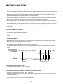
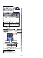
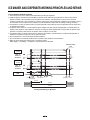
2-4. Ice Ejection Control Function
1. This is to eject ice from ice maker cube mould after ice making is completed.
2. If Hall IC signal is on within 3.6 seconds after ice ejection motor rotates in normal direction, it does not proceed ice
ejection but waits. If the ice bucket is full, ice ejection motor rotates in normal direction in every hour to check the
condition of ice bucket. If the ice bucket is not full, the water supply control starts after completion of ice ejection control. If
the ice bucket is full, ice ejection motor rotates in reverse direction and sops under ice making or waiting conditions.
3. If ice bucket is not full, ice ejection starts. The cube mould tilts to the maximum and ice is separated from the mould and
ice checking lever raises.
4. Ice ejection motor stops for 1 second if Hall IC signal changes from OFF (low) to ON (high) after 3.6 seconds when ice
ejection motor rotates in normal direction. If there is no change in Hall IC signals within 1 minute after ice ejection motor
operates, ice ejection motor stops as ice ejection motor or hall IC is out of order.
5. If ice ejection motor or Hall IC is abnormal, ice ejection motor rotates in normal direction to exercise initial operation. It
resets the ice maker if ice ejection motor or Hall IC is normal.
6. The mould stops for 1 second at maximum tilted conditions.
7. The mould returns to horizontal conditions as ice ejection motor rotates in reverse direction.
8. When the mould becomes horizontal, the cycle starts to repeat:
Water Supply → Ice Making → Ice Ejection → Mould Returns to Horizontal
Maximum tilting
point
Ice bucket is
not full
HALL IC
OUTPUT
SIGNALS
Ice bucket is
not full
HALL IC
OUTPUT
SIGNALS
ICE CHECKING LEVEL 30°
ICE CHECKING
AXIS
Lock
Ice making
Ice Checking
(Original point)
2±1 sec
Horizontal
Conditions
Ice Ejection
9±3 sec
8±3 sec
<Timing Chart During Ice Ejection>
Lock
Level Retrun
Conditions
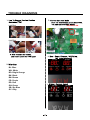
ICE MAKER AND DISPENSER WORKING PRINCIPLES AND REPAIR
2-5 Test Function
1. It is to force the operation during operation test, service, and cleaning. The test switch is mounted under the automatic
ice maker. The test function starts when the test switch is pressed for more than 0.5 second.
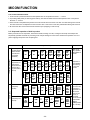
2. Test button does not work during ice ejection and water supply. It works when it is in the horizontal conditions. If mould is
full of ice during test function operation, ice ejection control and water supply control do not work.
3. When test switch is pressed for more than 0.5 second in the horizontal conditions, ice ejection starts irrespect of the
mould conditions. Water shall be splashed if test switch is pressed before the water in the mould freezes. Water shall be
supplied while the mould returns to the horizontal conditions after ice ejection. Therefore the problems of ice ejection,
returning to the horizontal conditions, and water supply can be checked by test switch. When test function performs
normally, buzzer sounds and water supply shall carry out. Check it for repair if buzzer does not sound.
4. When water supply is completed, the cycle operates normally as follows: Ice making → Ice ejection → Returning to
horizontal conditions → Water supply
5. Remove ice from the ice maker cube mould and press test switch when ice maker cube mould is full of ice as ice ejection
and water supply control do not work when cube mould is full of ice.
2-6. Other functions relating to freezer compartment door opening
1. When freezer door is open, ice dispenser stops in order to reduce noise and ice drop.
2. When freezer door is open during ice ejection and cube mould returning to horizontal condition, ice ejection and cube
mould level return proceed.
3. When freezer door is open, geared motor and cube ice solenoid immediately stop and duct door solenoid stops after 5
seconds.
4. Water dispenser stops in order to protect water drop when freezer door is open.
5. Test function operates normally irrespect of refrigearator compartment door opening.
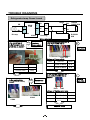
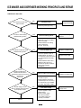
ICE MAKER AND DISPENSER WORKING PRINCIPLES AND REPAIR
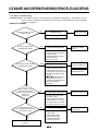
3. Ice Maker Troubleshooting
* Troubleshooting: it is possible to confirm by pressing freezer and refrigerator temperature control buttons for more
than 1 second. (ice maker is normal if all leds are on): refer to trouble diagnposis function in MICOM
function 2-8 (page 18)
<GW-P/L227: 88-LED>
Is DC Power (5V and 12V)
output normal?
No
Failed DC Power
Change main PWB
• Check DC power (5V, 12V).
Yes
Is cube ice led off during
troubleshooting check?
Yes
Yes
No
Yes
Normal
Failed ice maker unit test switch
Replace Ice Maker Unit
Replace Main PWB
Replace Ice maker Unit
• Are both ends 5,6 of CON8
test switch open?
• Defects between test switch
and board (Pin No. 40 of IC1).
• Are both ends (3,4) of CON8
ice maker stop switch short?
Yes
Is water suppy normal
after Ice ejection and level return
by ice ejection motor?
Failed Ice Maker Unit
• Is the resistance of both ends
9,10 of ice ejection motor of
CON8 between 18 and 22Ω?
• Is ice ejection motor drive circuit
(IC11 and peripheral circuits)
normal?
• Defects between Hall IC and
Board (Pin No. 42 of IC1).
• Confirm ice ejection and level
return when pressing
test switch.
No
Are ice
ejection and level return
normal when test switch is
pressed for more than 0.5 second?
Does the bell
sound once?
Replace Ice making
Sensor
• Check the resistance of
both ends (1,2) of ice making
sensor of CON8.
• Defects between ice making
sensor and board
(Pin No. 60 of IC1)
No
Is Crushed Ice LED off during
troubleshooting check?
Failed ice making sensor
No
Poor water supply
• Is power applied to water
supply valve?
• Does the water supply
valve work normally?
• Is the water supply line
normally connected?
Replace water
supply valve
ICE MAKER AND DISPENSER WORKING PRINCIPLES AND REPAIR
<GW-P/L227: Bar-LED>
Is DC Power (5V and 12V)
output normal?
No
Failed DC Power
Change main PWB
• Check DC power (5V, 12V).
Yes
Is cube ice led off during
troubleshooting check?
Yes
Yes
No
Yes
Normal
Failed ice maker unit test switch
Replace Ice Maker Unit
Replace Main PWB
Replace Ice maker Unit
• Are both ends 5,6 of CON8
test switch open?
• Defects between test switch
and board (Pin No. 42 of IC1).
• Are both ends (3,4) of CON8
ice maker stop switch short?
Yes
Is water suppy normal
after Ice ejection and level return
by ice ejection motor?
Failed Ice Maker Unit
• Is the resistance of both ends
9,10 of ice ejection motor of
CON8 between 18 and 22Ω?
• Is ice ejection motor drive circuit
(IC11 and peripheral circuits)
normal?
• Defects between Hall IC and
Board (Pin No. 46 of IC1).
• Confirm ice ejection and level
return when pressing
test switch.
No
Are ice
ejection and level return
normal when test switch is
pressed for more than 0.5 second?
Does the bell
sound once?
Replace Ice making
Sensor
• Check the resistance of
both ends (1,2) of ice making
sensor of CON8.
• Defects between ice making
sensor and board
(Pin No. 59 of IC1)
No
Is Crushed Ice LED off during
troubleshooting check?
Failed ice making sensor
No
Poor water supply
• Is power applied to water
supply valve?
• Does the water supply
valve work normally?
• Is the water supply line
normally connected?
Replace water
supply valve
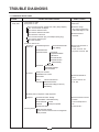
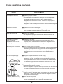
TROUBLE DIAGNOSIS
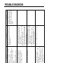
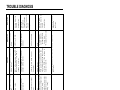
1. TROUBLE SHOOTING
CLAIMS.
1. Faulty start
CAUSES AND CHECK POINTS.
HOW TO CHECK
* Measuring instrument :
Multi tester
1) No power on outlet.
2) No power on cord.
Bad connection between adapter and outlet. (faulty adapter)
The Inner diameter of adapter.
The distance between holes.
The distance between terminals.
The thickness of terminal.
Bad connection between plug and adapter (faulty plug).
The distance between pins.
Pin outer diameter.
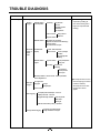
3) Shorted start circuit.
No power on Disconnected copper wire.
power cord.
Power cord is disconnected.
Faulty soldering.
Internal electrical short.
Faulty terminal contact.
Loose contact.
- Large distance between
male terminal.
- Thin female terminal.
■ Check the voltage.
If the voltage is within ±85%
of the rated voltage, it is OK.
■ Check the terminal
movement.
■ Check both terminals of
power cord.
Power conducts : OK.
No power conducts : NG
Terminal disconnected.
Bad sleeve assembly.
Disconnected.
O.L.P is off.
Weak connection.
Short inserted cord length.
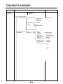
Worn out tool blade.
Capacity of O.L.P is small.
Characteristics of O.L.P is bad.
Bad connection.
Power is
Inner Ni-Cr wire blows out.
disconnected.
Bad internal connection.
Faulty terminal caulking (Cu wire is cut).
Bad soldering.
■ Check both terminals of
O.L.P.
If power conducts : OK.
If not : NG.
No electric power on compressor. - Faulty compressor.
Faulty PTC.
Power does not conduct. - Damage.
Bad characteristics. - Initial resistance is big.
Bad connection with Too loose.
compressor.
Assembly is not possible.
Bad terminal connection.
4) During defrost.
Start automatic defrost.
Cycle was set at defrost when the refrigerator
was produced.
■ Check the resistance of both
terminals.
At normal temperature 6 :
OK.
If disconnected : ∞.
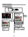
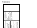
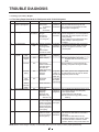
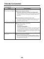
TROUBLE DIAGNOSIS
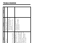
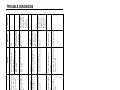
CLAIMS.
2. No cooling.
CAUSES AND CHECK POINTS.
2) Refrigeration system is clogged.
Moisture
clogged.
Residual moisture
in the evaporator.
Air Blowing.
Not performed.
Too short.
Impossible moisture
confirmation.
Low air pressure.
Leave it in the air.
Caps are missed.
No electric
power on
thermostat.
HOW TO CHECK
■ Check the clogged
evaporator by heating (as
soon as the cracking sound
begins, the evaporator start
freezing)
During rest time.
After work.
Residual moisture.
Not dried in the compressor.
Elapsed more than 6 months after drying
Caps are missed.
No pressure when it is open.
Insufficient drier
capacity.
Dry drier - Drier temperature.
Leave it in the air.
Check on package
condition.
Good storage after
finishing.
Residual moisture
in pipes.
Caps are missed.
During transportation.
During work.
Air blowing. Not performed.
Performed.
Too short time.
Low air pressure.
Less dry air.
Moisture penetration - Leave it in the air. - Moisture penetration.
into the refrigeration oil.
■ The evaporator does not cool
from the beginnig (no evidece
of misture attached).
The evaporator is the same
as before even heat is
applied.
Short pipe insert.
Weld joint
clogged.
Pipe gaps.
Too large.
Damaged pipes.
Too much solder.
The capillary tube inserted depth. - Too much.
Drier cloggeing.
Capillary tube melts. - Over heat.
Clogged with foreign materials.
Desiccant powder.
Weld oxides.
Drier angle.
Reduced cross section by cutting. - Squeezed.
Foreign material clogging.
Compressor cap is disconnected.
Foreign materials are in the pipe.
TROUBLE DIAGNOSIS
CLAIMS.
3. Refrigeration
is weak.
CAUSES AND CHECK POINTS.
1) Refrigerant Partly leaked.
Weld joint leak.
Parts leak.
2) Poor defrosting capacity.
Drain path (pipe) clogged.
HOW TO CHECK
■ Check visually.
Inject P/U into drain hose.
Foreign materials
penetration.
Inject through the
hole.
Seal with drain.
P/U lump input.
Screw input.
Other foreign materials
input.
Cap drain is not disconnected.
Defrost heater does not
generate heat.
Parts
disconnected.
Heater
Sheath
Wire is cut.
- Lead wire.
- Heating wire.
- Contact point
between heating and
electric wire.
Dent by fine evaporator.
Heating wire is corroded
- Water penetration.
Bad terminal connection.
■ Check terminal
Conduction: OK.
No conduction: NG.
If wire is not cut, refer to
resistance.
P=Power
V=Voltage
R=Resistance
V2
P= —
R
V2
R= —
P
TROUBLE DIAGNOSIS
CLAIMS.
3. Refrigeration
is weak.
CAUSES AND CHECK POINTS.
Residual
frost.
Weak heat from heater.
HOW TO CHECK
Sheath Heater - rated.
Heater plate - rated.
Too short defrosting time.
Defrost Sensor.
- Faulty characteristics.
Seat-D(missing, location. thickness).
Structural fault.
Gasket gap.
Air inflow through the fan motor.
Bad insulation of case door.
No automatic defrosting.
Defrost does not return.
3) Cooling air leak.
Bad gasket adhestion
Door sag.
Gap.
Bad attachment.
Contraction.
Bad adhesion.
Weak binding force at hinge.
4) No cooling air circulation.
Faulty fan motor.
Fan motor.
Door switch.
Self locked.
Wire is cut.
Bad terminal contact.
Faults.
Contact distance.
Button pressure.
Melted contact.
Contact.
Refrigerator and freezer switch reversed.
Button is not pressed. Poor door
attachment.
Door liner
(dimension).
Contraction inner
liner.
Misalignment.
Bad terminal
connection.
P/U liquid leak.
■ Check the fan motor
conduction: OK.
No conduction: NG.
TROUBLE DIAGNOSIS
CLAIMS.
3. Refrigeration
is weak.
CAUSES AND CHECK POINTS.
HOW TO CHECK
4) No cooling air circulation.
Faulty fan motor.
Fan is
constrained.
Fan shroud contact. - Clearance.
Damping evaporator contact.
Accumulated residual frost.
Small cooling air
discharge.
Insufficient
motor RPM
Fan overload. - Fan misuse.
Bad low termperature RPM characteristics.
Rated power misuse.
Low voltage.
Faulty fan.
Shorud.
Fan misuse.
Bad shape.
Loose connection. - Not tightly connected.
Insert depth.
Bent.
Ice and foreign materials on rotating parts.
5) Compressor capacity.
Rating misuse.
Small capacity.
Low valtage.
6) Refrigerant
too much or too little.
Malfunction of charging cylinder.
Wrong setting of refrigerant.
Insufficient compressor. - Faulty compressor.
7) Continuous operation
- No contact of temperature controller. - Foreign materials.
8) Damper opens continuously.
Foreign materials
P/U liquid dump.
jammed.
EPS water sediment.
Screw.
Failed sensor. - Position of sensor.
Characteristics
Bad characteristics of its own temperatue.
of damper.
Parts misuse.
Charge of temperature - Impact.
characteristics.
9) Food storing place. - Near the outlet of cooling air.
■ Check visually after
disassembly.
■ Check visually after
disassembly.
TROUBLE DIAGNOSIS
CLAIMS.
4. Warm
refrigerator
compartment
temperature.
CAUSES AND CHECK POINTS.
1) Colgged cooling path.
P/U liquid leak.
Foreign materials. –– P/U dump liquid.
2) Food storate.
5. No automatic
operation.
(faulty
contacts.)
Store hot food.
Store too much at once.
Door open.
Packages block air flow.
1) Faulty temperature sensor in freezer or refrigerator compartment.
Faulty contact.
Faulty temperature characteristics.
2) Refrigeration load is too much.
3) Poor insulation.
4) Bad radiation.
Food.
Too much food.
Hot food.
Frequent opening and closing.
Cool air leak.
Poor door close. – Partly opens.
High ambient temperature.
Space is secluded.
5) Refrigerant leak.
6) Inadequate of refrigerant.
7) Weak compressor discharging power.
Different rating.
Small capacity.
8) Fan does not work.
9) Button is positioned at "strong."
6. Dew and
ice formation.
HOW TO CHECK
1) Ice in freeezer compartment.
External air inflow. –– Rubber motor assembly direction(reverse).
Door opens
Weak door closing power.
but not closes.
Stopper malfunction.
Door sag.
Food hinders door closing.
Gap around gasket. –– Contraction, distortion, loose, door twisted, corner not
fully inserted.
Food vapor. –– Storing hot food. –– Unsealed food.
2) Condensation in the refrigerator compartment.
Insufficient closing.
Door opens
but not closes.
Door sag.
Food hinders door closing.
Gasket gap.
3) Condensation on liner foam.
Cool air leak
Not fully filled.
and transmitted.
Toop table part.
Out plate R/L part.
Flange gap. –– Not sealed.
Gasket gap.
■ Inspect parts measurements
and check visually.
TROUBLE DIAGNOSIS
CLAIMS.
6. Dew and
ice formation.
CAUSES AND CHECK POINTS.
HOW TO CHECK
4) Dew on door.
Dew on the duct door. - Duct door heater is cut.
Dew on the dispense
Recess Heater is cut.
recess.
Duct door is open. / Foreign material clogging.
Dew on the door surface.
Dew on the
gasket surface.
Not fully filled.
Surface.
Cormer.
P/U liquid contraction.
Liquid shortage.
Liquid leak.
Bad wing adhesion.
Wing sag(lower part).
Door liner shape mismatch.
Corner.
Too much notch.
Broken.
Home Bar heater is cut.
5) Water on the floor.
Dew in the refrigerator compartment.
Defrosted water overflows.
Clogged discharging hose.
Discharging hose
Evaporation tray located at wrong place.
location.
Tray drip.
Damaged.
Breaks, holes.
Small Capacity.
Position of drain.
7. Sounds
1) Compressor compartment operating sounds.
Compressor sound
Sound from machine itself.
inserted.
Sound from vibration.
Restrainer.
Rubber Too hard.
seat.
Distorted.
Aged.
Burnt.
Stopper. Bad Stopper Not fit
assembly.
(inner
diameter
of stopper).
Tilted.
Not
Compressor base not connected.
Bad welding compressor stand(fallen).
Foreign materials in the compressor
compartment.
O.L.P. sound.
Capacitor noise.
Pipe sound.
Chattering sound.
Insulation paper vibration.
Pipe contacts each other. – Narrow interval.
No vibration damper. Damping rubber-Q.
Damping rubber-S.
Capillary tube unattached.
TROUBLE DIAGNOSIS
CLAIMS.
7. Sounds
CAUSES AND CHECK POINTS.
1) Compressor compartment operating sounds.
Transformer sound.
Its own fault. –– Core gap.
Bad connection. –– Correct screw connection.
Drip tray vibration sound. Bad assembly.
Distortion.
Foreign materials inside.
Back cover machine sound.
Condenser drain sound.
Bad connection.
Partly damaged.
Not connected.
Bad pipe caulking.
2) Freezer compartment sounds.
Fan motor sound.
Normal operating sound.
Vibration sound.
Aged rubber seat.
Bad torque for assembling motor
bracket.
Sounds from fan
contact.
Fan guide contact.
Shroud burr contact.
Damping evaporator contact.
Residual frost contact.
Poor treatment Cord heater.
Narrow evaporator interval.
Unbalance fan sounds.
Unbalance.
Surface machining conditions.
Fan distortion.
Misshappen.
Burr.
Ice on the fan. –– Air intake (opposite to motor
rubber assembly.)
Motor shaft
contact sounds.
Resonance.
Evaporator noise.
Supporter disorted.
Tilted during motor assembly.
Evaporator pipe contact. –– No damping evaporator.
Sound from refrigerant. –– Stainless steel pipe shape in
accumulator.
Sound from fin evaporator and pipe during expansion
and contraction.
3) Bowls and bottles make contact on top shelf.
4) Refrigerator roof contact.
5) Refrigerator side contact.
6) Insufficient Lubricants on door hinge.
HOW TO CHECK
TROUBLE DIAGNOSIS
CLAIMS.
8. Faulty lamp
(freezer and
refrigerator
compartment).
CAUSES AND CHECK POINTS.
1) Lamp problem.
2) Bad lamp assembly.
3) Bad lamp socket.
Disconnection.
Short.
HOW TO CHECK
Filament blows out.
Glass is broken.
Not inserted.
Loosened by vibration.
Bad soldering.
Bad rivet contact.
Water penetration.
Low water
level in tray.
Bad elasticity of contact.
Bad contact(corrosion).
4) Door switch.
Its own defect.
Refrigerator and freezer switch is reversed.
Travlel distance.
Bad connection.
Bad terminal contact.
P/U liquid leak..
9. Faulty internal
voltage(short).
1) Lead wire is damaged.
Wire damage when assembling P.T.C. Cover.
Outlet burr in the bottom plate.
Pressed by cord heater. lead wire, evaporator pipe.
2) Exposed terminal.
Compressor Compartment terminal. - Touching other
components.
Freezer compartment terminal. - Touching evaporator pipe.
3) Faulty parts.
Transformer.
Coil contacts cover.
Welded terminal parts contact cover.
Compressor.
Bad coil insulation.
Plate heater.
Melting fuse.
Sealing is broken.
Moisture penetration.
Cord heater.
Pipe damaged.
Moisture penetration.
Bad sealing.
Sheath heater.
■ Connect conduction and
non-conduction parts and
check with tester.
Conduction: NG.
Resistance∞: OK.
TROUBLE DIAGNOSIS
CLAIMS.
10. Structure,
appearance
and others.
CAUSES AND CHECK POINTS.
1) Door foam.
Sag.
Weak torque of
hinge connection.
Weak gasket
adhesion.
Fixed tape.
Bolt is loosened during
transportaion.
Not tightly fastened.
Screw worn out .
Adhesion surface.
Not well fixed.
Noise during
operation.
Hinge interference.
Malfunction.
Not closed Interference between door liner and inner liner.
Refrigerator
Stopper worn out.
compartment is
Bad freezer compartment door
opened when freezer
assembly.
compartment is
No stopper.
closed (faulty stopper).
2) Odor.
Temperature of
refrigerator
compartment.
High.
Bigger door foam.
Hinge-Pin tilted-Poor flatness.
No washer.
No grease and not enough
quantity.
Faulty damper control.
Button is set at "weak".
Door is open (interference by
food).
Deodorizer.
No deodorizer.
Poor capacity.
Food Storage.
Seal condition.
Store special odorous food.
Long term storage.
Others.
Odors from chemical procucts.
HOW TO CHECK
operate.
does not
Compressor
Problems
Causes
- Compressor is frozen.
- Faulty PTC.
2-2. Compressor
penetration).
(tracking due to moisture and dust
- Short circuit of components
- High voltage.
- Electricity leakage.
- Short circuit by insects.
connected to high voltage.
- Low voltage products are
Fuse blows out. - Short circuit by wrong connection.
low voltage).
problem(ex. short, high voltage,
- Find and remove the cause of
- Reconnect the connecting parts.
-Reconnect the connecting parts.
-Replace the components.
Measures
OLP
contacted.
It starts as soon as it is
Power
Main winding
Auxiliary winding
• Refer to weld repair procedures.
evacuate, and recharge refrigerant.
compressor with new one, weld,
- Not operate: Replace the frozen
apply power directly to the
compressor to force operation.
- Operates: Check other parts.
- During forced operation:
- Check other parts.
- If it is not infinite, it is normal.
with new one.
- If resistance is infinite, replace it
Measures
normal(capacitor, PTC, OLP),
- If compressor assembly parts are
Vlaue:∞ is defective.
- Check the resistance.
Checks
with testerf (if it is 0Ω, it is shorted).
- Check the resistance of power cord
(between power cord and products). - Replace with rated fuse.
- Check the input volt are with tester
or visually.
- Check the fuse with tester
- Check visually.
- Faulty connection between plug
and adapter.
- Check visually.
- Check the voltage with tester.
- Power cord cut.
- Faulty connector insertion.
Checks
outlet.
Causes
No power on
Problems
2-1. Power
2. Faults
Remarks
the cause and prevent.
frequently, reconfirm
■ If fuse blowns out
its specification.
fuse after confirming
- Replace with rated
Remarks
TROUBLE DIAGNOSIS
refrigerator and wall (50 mm in
compressor compartment.
from grill for easy heat radiation.
while the refrigerator is off.
cleaner from the coils condenser
refrigerator is on.
performs while the
50mm).
- Remove dust and contaminants
broken if cleaning
- The fan may be
Remarks
refrigerator and walls (minimum
- Keep clearance between
attach sheets.
- Door liner bent:replace door or
- Door sag: fix door.
- Replace door switch.
- Confirm icing causes and repair.
deformation).
is constrained by shroud
(Repair and/or replace shroud if fan
- Maintain clearance and remove ice
- Reconnect and reinsert.
- Replace fan motor.
Measures
- Check dust on the coils condenser. - Remove the dust with vacuum
compressor compartment.
- Check dust on the grill in
minimum).
- Check the clearance between the
button: Check visually.
- Door cannot press door switch
Press button to check operation.
- Faulty button pressure and contact:
Press button to check
- Iced button (faulty) operation:
Confirm visually.
– Fan icing:
visually.
contact: Confirm
- Fan constraint. – Fan shroud
terminal visually.
- Bad terminal contact: Check
- Wire is cut.
rotation.
Bad radiation conditions in
switch operation.
Faulty fan motor due to faulty door
compartment.
- Rotate rotor manually and check
0Ω: short.
∞Ω: cut.
in the freezer
tester.
fan motor.
temperature
Checks
Poor cool air circulation due to faulty - Lock –– Check resistance with a
Causes
High
Problems
2-3. Temperature
TROUBLE DIAGNOSIS
Shortage of refrigerant.
auxiliary in the compressor
compartment.
refrigerant.
Weld the leaking part, recharge the
Measures
- If it does not, it is not good.
surface, it is OK.
refrigerant.
refrigerant, and recharge new
- No leaking, remove the remaining
refrigerant.
compartment.
- If the frost forms evenly on the
evacuate, and recharge the
of evaporator in the freezer
Check frost formation on the surface - Find out the leaking area, repair,
freezer compartment).
compartment and evaporators in
5. Check other parts (compressor
happen during bending).
compartment (cracks can
condenser pipe in compressor
4. Check bending area of wire
(Cu + Fe / Fe + Fe).
3. Check silver soldered parts.
sealing pipe (low pressure side).
2. Check the end of compressor
compartment (high pressure side).
drier inlet and outlet and drier
in the freezer
Check sequence
Checks
1. Check the welded parts of the
Refrigerant leak.
Causes
temperature
High
Problems
2-4. Cooling
Drier must be replaced.
Drier must be replaced.
Remarks
TROUBLE DIAGNOSIS
the refrigerant.
joints might be clogged.
1. Check cooling fan operation.
compartment.
disconnected from the motor.
2. Check that cooling fan is
Check sequence.
Faulty cooling fan in the compressor
compartment.
evaporator in the freezer
and the frost forms partly on the
condenser is warm, It is not warm
1. Manually check whether
(discharge) in compressor.
causes, evacuate, and recharge
joints might be colgged.
Check sequence.
Disconnect with torch, remove the
If it is not, condenser outlet weld
Leak at loop pipe weld joint
joints might be clogged.
If it is warm, it's OK.
and assembly sequence.
■ Refer to fan motor disassembly
damage and reassemble it.
- If fan is disconnected, check fan
- Replace if motor does not operate.
evacuate, and recharge refrigerant.
Replace the compressor, weld,
seal refrigerant.
condenser discharging line weld
pipe is warm.
- If it's warm, it's OK. If it's not,
weld, evacuate, and recharge
2. Manually check whether hot line
Remove the causes of clogging,
If it is warm, it is OK.
If it is not, compressor discharging
the pipes, and check the clogging.
weld joints with touch, disconnect
- Heat up compressor discharging
Measures
compartment.
1. Check temperature of condenser
Check sequence.
Checks
manually.
Cycle pipe is clogged.
Causes
the freezer
temperature in
High
Problems
Drier must be replaced.
Direr must be replaced.
Remarks
TROUBLE DIAGNOSIS
No defrosting.
Problems
Causes
0Ω: Short. ∞Ω: Cut.
through the hole to check.
1. Impurities.
2. Confirm the capacity after
assembly).
Tolerance: ±7%
Compare P and lavel capacity.
V2 (V: Rated voltage of user country)
P= ––
R (R: Resistance of tester[Ω])
into the formula.
substituting the resistance value
1. Check heater label.
1. Confirm in the Sucking duct.
Wrong heater rating (or wrong
Heater plate(Ice in the gap).
Gap between Sucking duct and
(check drains outside).
2. Put hot water into the drain
of ice, insert the copper line
2. Ice.
explanations.
• Parts replacement: Refer to parts
Heating wire is short and wire is cut.
Measures
- How to replace: Refer to main parts.
Faults:replace.
the disconnected parts.
bottom with hand and assemble
2) Push the Heater plate to drain
gap melts down.
supply hot water until the ice in the
impurities and ice in the gap, and
1) Turn off the power, confirm
disconnected parts.
duct manually and assemble the
4) Push the heater plate to sucking
3) Check the water outlet.
2) Put in hot water to melt down frost.
frost is severe.)
3hours and pour in hot water if
copper wire.(Turn off more than
1. Confirm foreign materials. In case 1) Push out impurities by inserting
are clogged:
Sucking duct and discharging hole
Tens to thousands Ω: Short.
3) Heating wire at lead wire contacts
is cut.
surface.
housing terminal and heater
2) Lead wire of heater is cut.
inserting into the evaporator.
Tens to thousands Ω: OK.
2. Check the resistance between
is shorted.
1) Heating wire is damaged when
0Ω: Short. ∞Ω: Cut.
1. Check the resistance of heater.
Checks
the heating wire is cut or the circuit
Heater does not generate heat as
2-5. Defrosting failure
repair.
lead wire is accessible to
contraction tube if the cut
insulation tape and heat
Seal the lead wire with
Remarks
TROUBLE DIAGNOSIS
is OK).
insertion into housing of heater,
from the assembly).
model: disconnect thermostat
described in 1, 2 (mechanical
3. Check the parts which have faults
the sheath heater.
on the heater. Do not put hands on
defrost, and confirm heat generation
around the housing visually,
compartment, check the connection
2. Disconnect parts in the refrigerator
operates (If it operates, motor fan
melting, fuse and motor fan).
door, check that motor fan
contact and insertion (bad connector
1. Turn on power, open or close the
copper not to impair heating wire).
wire into the duct (soft and thin
2. Check by inserting soft copper
1. Check the inner duct with mirror.
and bad defrosting due to faulty
Bad cool air inflow and discharge,
3) Icing by the gap of heater plate.
the gap of heater plate.
2) Icing by cool air inflow through
duct.
1) Icing by foreign materials in the
Ice in the Sucking duct.
If ∞Ω: wire is cut.
2) Bad soldering.
- Check melting fuse with tester. If 0Ω: OK.
Melting fuse blows out.
No defrosting
Checks
1) Lead wire is cut.
Causes
Problems
with a new one.
remove the parts and replace it
2) If the parts are very damaged,
assembled parts.
housing and reassemble wrongly
1) Check the faulty connector of
3) Reassemble the heater plate.
defrosting.)
on, melt the frost by forced
the ice melt naturally. (If power is
support the front side legs, and let
2) Raise the front side(door side),
1) Turn power off.
resistance with a tester.
- Check wire color when maeasuring
Faullty parts: parts replacement.
Measures
Remarks
TROUBLE DIAGNOSIS
pipe icing.
grille.
and high load.
- High temperature, high moisture,
- Door opens.
this machine.
5) Customers are not familiar with
- Check ice on the ceilings.
closing.
- Check food interferes with door
and refrigerator compartment.
- Check ice on intake port of freezer
- Defective defrost sensor.
- Defrosing cycle.
after dissembling shroud and fan
- Check frost on the evaporator
- Check parts are faulty.
pressed on "weak").
is overcooled (when button
- Check refrigerator compartment
- Check door assembly conditions.
- Check gasket attached conditions.
compartment.
freezer and refrigerator
- Check icing at intake ports of
dissembling the container box.
baffle and cool air path (pipe) after
- Check icing on the surface of
are clogged).
(check discharge and intake port
- Check the food is stored properly
Checks
- Heater wire is cut.
4) Bad defrosting
- Faulty MICOM (faulty sensor)
compartment.
- Faulty damper in the refrigerator
compartment.
3) Overcooling in the refrigerator
- Faulty assembly.
- Faulty gasket.
compartment.
2) Faulty door or refrigerator
- Bad defrosting.
the discharge port.
- Pipe icing.
- Discharging
- Sealing is not good.
- Too much food is stored and clogs
- Damper icing.
refrigerator compartment.
- Clogged intake port in the
refrigerator
compartment.
1) Bad circulation of cool air.
Causes
Icing in the
Problems
2-6. Icing
- Be acquainted with how to use.
evaporator and pipe.)
- Check defrosting. (Check ice on the
- Check parts related to defrosting.
- Replace faulty parts.
- Door assembly and replacement.
conditions and replace it.
- Correct the gasket attachment
evaporator and pipes.)
defrosting, check ice in the
- Check defrost. (After forced
it if it has defects.
- Check the damper and replace
- Sealing on connecting parts.
- Be acquainted with how to use.
Measures
suppresses sublimation.
circulation, and
interferes with cool air
condensed and iced,
refrigerator, being
can be sucked into the
on the evaporator but
- Moisture cannot frost
cannot be repaired.
be done when it
- Replacement should
defrosting.
is caused by faulty
related parts if problem
- Check the defrost
Remarks
TROUBLE DIAGNOSIS
Causes
- Discharging port is Clogged.
compartment.
- Intake port is colgged in the freezer
- Bad defrosting.
shute.
- Icing in the
- High moisture food(water) is stored.
- Door opens.
use.
5) User is not familiar with how to
- Defrosting cycle
- Faulty defrost sensor.
- Heater wire is cut.
4) Bad defrosting.
- Faulty MICOM.
-Replace defective parts.
- Door assembly and replacement.
conditions and replace it.
- Correct the gasket attachement
defrosting).
evaporator and pipes after forced
- Check defrost (Check ice on the
- Be acquainted with how to use.
Measures
- Check ice on the ice tray.
- Check food holds door open.
refrigerator compartment.
- Check ice on the intake port in the
dissembling shroud and grille.
- Be acquainted with how to use.
defrosting.)
evaporator and pipes after forced
- Check defrosting.(Check ice on the
- Check frost on the evaporator after - Check parts related to defrosting.
though the notch is set at "weak".
refrigerator compartment even
over freezing happens in the
compartment is satisfactory, but
- The Temperature of freezer
intermittently)
(Check if it is operated
- Refrigerator operates pull down.
3) Over freezing in the freezer
compartment.
- Check door assembly conditions.
conditions.
- Check gasket attachment
refrigerator compartment.
- Check icing at intake port of
dissembling shroud and fan grille.
- Check frost on the evaporator after
volume(Less than 75%).
- Check food occupation ratio in
and discharging port of cooling air.)
visually.(Check clogging at intake
- Check food storage conditions
Checks
- Faulty assembly
- Faulty gasket
- Food surface. 2) Bad freezer compartment door
area.
- Basket(rack)
discharging port.
- Cool air
compartment.
- Wall of freezer - Too much food is stored.
grille.
- Surface of fan
compartment.
Ice in the freezer 1) Bad cooling air circulation.
Problems
be repaired.
- Replace when it can not
the faulty defrosting.
problem is caused by
to defrosting if the
- Check the parts related
Remarks
TROUBLE DIAGNOSIS
"Whizz" sound
Problems
2-7. Sound
bell mouth of the fan guide.
conditions in pipes.
sound).
compressor compartment.
4. Fan operation sound in the
compartment.
blade damage.
drip tray.
conditions at condenser and
4.3 Check the screw fastening
4.2 Check drip tray leg insertion.
refrigerator.
4.1 Same as fan confirmation in the
and aging conditions.
3.4 Check fan motor rubber insertion
3.3 Check fan motor.
structures.
3.2 Check the interference with
freezer shroud.
pipes and suction pipe touch
9) Leave a clearance if evaporator
sound.
8) Reassemble the parts which make
interfering parts and seal gaps in
the structures.
-driver (check the change of
2.3 Touch pipes with hands or screw 7) Leve a clearance between
6) Adjust fan to be in the center of
motor.
5) Replace defective fan and fan
4) Avoid pipe interference.
reduces noise in the pipe.
3) Insert rubber where hand contact
are sagged and aged.
2) Replace rubber and seat if they
1) Maintain horizontal level.
Measures
2.2 Check rubber inserting
and their interference.
connected to the compressor
2.1 Check the level of pipes
conditions (sagging and aging).
1.2 Check the rubber seat
refrigerator.
1.1 Check the level of the
Checks
3. Fan operation sound in the freezer 3.1 Check fan insertion depth and
connected to the compressor.
2. Pipes resonat sound which is
operation.
1. Loud sound of compressor
Causes
Remarks
TROUBLE DIAGNOSIS
Causes
vibration.
5. Other structure and parts
4. Moving wheel vibration.
3. Compressor stopper vibration.
compartment.
tube touching in the compressor.
2. Pipes interference and capillary
the refrigerator.
("Click").
them (freezer shroud or inner case).
structures, leave a clearance between
2) If evaporator pipe contacts with other
between operation and defrosting
can make sounds.
and that the temperature difference
1) Explain the principles of refrigeration
vibtates severely.
4) Replace compressor stopper if it
(especially, compressor and pipe).
and restrainer if it is severe.
3) Reduce vibration with rubber
interfere with each other.
2) Leave a clearance where parts
vibration is severe.
and insert foam or cushion where
1) Reassemble the vibrating parts
Measures
shelves, and pipes in the
sources.
1-1 Check time and place of sound
5-1 Touch other structures and parts.
moving wheels.
4-1 Check vibration of front and rear
vibration.
3-1 Check compressor stopper
cover back.
2-2 Check capillary tube touches
compartment with hands.
2-1. Touch pipes in the compressore
on the shelves.
1-2. Check light food and container
shelves in the refrigerator
1-1. Remove and replace the
Checks
refrigerator.
and contraction of evaporator,
Irregular sound. 1. It is caused by heat expansion
("Cluck")
Vibration sound. 1. Vibration of shelves and foods in
Problems
Remarks
TROUBLE DIAGNOSIS
Causes
Checks
compartment.
- Seal the gap with sealant between out
and inner cases of hinge in door.
below atomosphere and sucks air into
the refrigerator, making the whistle
sound.
defrosting in the compressor
- Broaden the cap of discharge hose for
closes.
closing the refrigerator or freezer doors.
- Check the sound by opening and
When door closes, the internal pressure
of the refrigerator decreases sharply
when door
accumulator with foam and restrainer.
- If sound is servere, wrap the
internal pressure difference.
and refrigerant flowing phenomenon by
- Explain the principles of freezing cycles
cycles.
- Explain the principles of freezing
Sound of whistle
turned off.
condenser and evaporator.
turned on.
- Check the sound when compressor is
orifice in accumulator internal pipes by
flowing sound.
- Check the sound when compressor is
pipes or detach in the compressor
capillary tube weld joints.
compartment.
- Fasten the capillary tube to suction
capillary tube again (depth:15±3mm)
- If it is continuous and servere, insert
joints and attach another restrainer.
evaporator and capillary tube weld
- Check the restrainer attached on the
Measures
conditions on the evaporator and
the pressure difference between
It happens when refrigerant passes
Water boiling or
starts operation after forced defrosting.
sound).
- Check the restrainer attachment
- Check the sound when the refrigerator
initial installation.
as animals crying
(almost the same at the end of capillary tube.
Sound "Burping" It happens when refrigerant expands - Check the sound of refrigerant at the
Problems
Remarks
TROUBLE DIAGNOSIS
deodorizer.
Odor from the
Odors of mixed food and plastic
Plastic Odor.
Odor from the old deodorizer.
odors.
Food (garlic, kimchi, etc)
Causes
Food Odor.
Problems
2-8. Odor
- Check the deodorizer odors.
- It happens in the new refrigerator.
plastic bowl and bag.
- Check wet food is wrapped with
- Chedk food cleanliness.
- Check the food in the vinyl wraps.
wall are stained with food juice.
- Check the shelves or inner
- Check the food is not wrapped.
Checks
deodorants.
- Remove and replace the
then in the shiny and windy place.
- Dry the deodorizer with dryer and
or odorous foods.
plastic bag or wraps with wet food
- Persuade customers not to use
- Clean the refrigerator.
button at "strong".
- Clean the refrigerator and set
container instead of vinyl wraps.
- Store the food in the closed
windy place.
- Dry deodorizer in the shiny and
Measures
*Deodorizer : option
Remarks
TROUBLE DIAGNOSIS
and display circuit.
module.
Defective LED
between Main PCB
damaged.
operation
STR Parts are
display LED
Check if STR No. 2 and 3 pins
are cut when power is off.
fuse is burnt out.
Defective LED.
more than one second.)
pressed at the same time for
key and power freezer key are
pressed (or when both freezer
Main PCB Test switch is
Check if all LEDs are on when
PCB.
Replace display
Lead Wire.
bad.
connect defective
Wire and directly
contact terminal to
display PCB with a tester.
connecting Main PCB and
Reconnect Lead
Replace parts.
Replace PCB fuse.
Replace regulator.
terminal connection is
PCB is cut or connector
main PCB and display
Check Lead Wire terminals
terminal with a tester.
PCB electric terminal
Lead Wire connecting
Check fuse in PCB electric
(7812, 7805).
Check voltage at input/output
terminals.
Defective regulator IC
circuit parts.
trans winding is cut).
DefectivePCB electric
fuse is burnt out.
PCB Trans temperature a tester. (If resistance is infinity,
PCB Trans winding is
cut.
Defective PCB trans.
or PCB.
Check resistance of PCB Trans Replace PCB Trans
input and output terminals with
PCB to display PCB.
connector.
Reconnect
Measures
and display circuit.
connection.
Visual check on connector
Checks
connection from main
Bad connector
Causes
between Main PCB
Bad connection
LEDS are off.
electric power.
Bad connection
Abnormal
All display
Symptom
Bad PCB
Problems
2-9. Micom
explanation.
circuit in circuit
Refer to display
dispenser.
model with
Applicable to
explanation.
circuit in circuit
Refer to electric
dispenser.
model without
Applicable to
Remarks
TROUBLE DIAGNOSIS
Bad cooling.
Problems
Faulty defrost.
driving relay.
diagnosis
functions.
function.
Refer to trouble
• Replace fan motor.
explanation.
circuit
refrigerator and
home bar).
driving circuits in
Refer to load
explanation.
circuit
table of sensor in
characteristics
resistance
Refer to
switch (freezer,
• Replace door
wire.
Reconnect lead
sensor housing
Repair main PCB
sensor.
Replace freezer
Refer to faulty defrost items in trouble diagnosis
normal, it is OK.
motor after pressing test switch
home bar).
• Defective fan motor
PCB power blue line and fan
(freezer, refrigerator,
of Main PCB. If the voltage is
Measure the voltage between
• Defective door switch
• Defective fan motor.
with a tester.
is cut.
motor.
sensor.
Check fan motor lead wire
circuits (main PCB sensor
housing).
substituted for other
Fan motor lead wire
Confirm the color of sensor in
Freezer sensor is
Defective freezer fan
sensor with a tester.
sensor parts.
sensor.
Check resistance of freezer
Defective Freezer
explanation.
driving circuit in
voltage is normal.
(RY1) or PCB.
Refer to load
Remarks
circuit
(5&7) after pressing main PCB
driving relay.
Replace relay
Wire.
Reconnect Lead
Measures
test switch once. It is OK if
Measure voltage at PCB CON1
with a tester.
Check compressor Lead Wire
Checks
Defective compressor
is cut.
Compressor Lead Wire
Causes
Defective freezer
not start.
temperature is
high.
Compressor does
Freezer
Symptom
TROUBLE DIAGNOSIS
Bad cooling
Problems
Refer to AC damper in parts
repair guide.
part.
Check AC damper
Motor driving relay in
Check if refrigerator sensor
is not fixed at cover sensor but
inner case visually.
sensor assembly
condition.
housing.)
sensor.
Defective refrigerator
circuit. (main PCB sensor
substituted for other
refrigerator sensor.
Fix again the
sensor housing.
Repair main PCB
Check the sensor color in the
Replace refrigerator
Refrigerator sensor is
Check the resistance of
refrigerator sensor with a tester. sensor.
Box Assembly.
or refrigerator control
Defective refrigerator
damper baffles
Replace AC damper
sensor parts.
wire is cut with a tester.
Ice formation on AC
Remove foreign
materials.
sensor
Check if AC damper Heater
damper baffles
PCB.
Replace relay or
box Assembly.
or refrigerator control
Replace AC damper
wire.
Reconnect lead
Measures
Defective refrigerator
Check AC damper baffle
visually.
Foreign materials in AC
PCB.
Refer to AC damper in parts
repair guide.
Check AC damper
cut with a tester.
and lead wire are cut.
temperature.
reed switch lead wire are
Check if AC damper motor and
Checks
motor and reed switch
Defective AC Damper. Check AC damper
Causes
Refrigerator
Wrong
Symptom
explanation.
table in circuit
characteristic
resistance
Refer to sensor
explanation.
in circuit
driving circuits
motor damper
Refer to single
Remarks
TROUBLE DIAGNOSIS
Defrost is not
Bad defrost.
pressed.
Disassemble frame display and confirm
visually.
Key is continuously depressed due to
structural interference.
structures.
interfering
Adjust or replace
lead wire.
button is
directly connect bad
wire and replace or
Reconnect lead
Replace door switch.
contact terminal to
not ring and
key does not
display button
Check input wire with a tester.
guide.
Refer to door switch in parts repair
switch with a tester.
Repair lead wire.
sensor.
with a tester.
Check lead wire related to door
Replace defrost
explanation.
circuit in circuit
Refer to display
explanation.
table of circuit
characteristic
resistance
Refer to sensor
explanation.
Check the resistance of defrost sensor
check in circuit
driving conditions
If the voltage is normal then it is OK.
or PCB.
with a tester after pressing main
Refer to load
Remarks
PCB test switch twice.
Replace relay
Wire.
Reconnect Lead
Measures
Check the voltage of CON2
tester.
Check if defrost lead wire is cut with a
Checks
sense even
terminal contact in main PCB and
display PCB connecting lead wire.
Buzzer does
Defective
does not work.
Key input wire is cut or bad connector
Defective door switch parts.
rings or door
opening alarm
main PCB to door switch.
continuously
buzzer
Defective connecting lead wire from
Buzzer
Defective defrost sensor parts.
Defective defrost driving relay.
Defrost lead wire is cut.
Causes
Defective
working.
Symptom
Problems
TROUBLE DIAGNOSIS
switch parts.
opening alarm
Check lead wire associated with door
Check resistance of parts with a tester.
parts.
Replace defective
dispenser.
Defective parts associated with water
Replace defective
parts.
Replace defective
relay.
relay.
Check relay with a tester
Check resistance of parts with a tester.
Check relay with a tester.
dispense.
Defective relay associated with water
dispenser solenoid).
dispense (geared motor, cube and
Defective parts associated with ice
dispenser solenoid).
dispense (geared motor, cube and
between 0V - 5V.
pressed. It is OK if voltage change is
Replace defective
Replace photo
coupler IC or PCB.
Check voltage change at photo coupler
output terminals with lever switch
Defective photo coupler IC parts.
Defective relay associated with ice
Refer to door switch in parts repair guide. Replace lever switch.
Defective lever switch parts
dispensed.
switch with a tester.
Main PCB to lever switch.
are not
Repair lead wire.
switch.
compartment door
Replace Freezer
Repair lead wire.
dispenser.
Check Lead Wire associated with lever
guide.
Refer to door switch in parts repair
switch.
Ice and water
Defective connecting lead wire from
Defective freezer compartment door
rings or door
does not work.
Defective connecting lead wire from
main PCB to door switch.
Buzzer
continuously
Bad water/ice
Door Buzzer
pressed.
with dispenser.
Check model
explanations.
button is
Refer to mode
function
Repair troubles
not sense even
Check trouble diagnosis function.
Remarks
indication in
Trouble mode indication.
Measures
but key does
Checks
Buzzer rings
Causes
display button.
Symptom
Defective
Problems
TROUBLE DIAGNOSIS
TROUBLE DIAGNOSIS
3. Cooling Cycle Heavy Repair
3-1. The Heavy Repair Standards for Refrigerator with R134a Refrigerant
NO.
1
Items
Pipe and piping
system opening time.
2
Welding.
3
N2 sealed parts.
4
Refrigeration
Cycle.
Unit
Min.
Nitrogen
Pressure.
Confirm N2
leak.
Evacuation
time
Vacuum
degree
Min.
Vacuum
EA
Vacuum
piping
EA
Pipe
coupler
EA
5
Outlet
(Socket)
Plug
Refrigerant weighing.
6
Drier replacement.
7
Leak check.
Torr
EA
Standards
Purposes
Remarks
Pipe:within 1 hour. To protect The opening time should be reduced to a
Comp:within
Moisture
half of the standards during rain and
10 minutes. Penetration. rainy seasons (the penetration of water
Drier:within
into the pipe is dangerous).
20 minutes.
Weld under
To protect - Refet to repair note in each part.
Nitrogen
oxide scale - R134a refrigerant is more susceptible to
atmosphere
formation.
leaks than R12 and requires more care
(N2 pressure:
during welding.
0.1~0.2 kg/cm2)
- Do not apply force to pipes before and
after welding to protect pipe from
cracking.
Confirm air leaking To protect - In case of evaporator parts, if it doesn't
sounds when
moisture
noise when removing rubber cap blow
removing rubber
penetration. dry air or N2 gas for more than 1 min
cap.
use the parts.
Sound:usable
No sound:not usable
More than
To remove
40 minutes.
moisture.
Below 0.03(ref)
Note:Only applicable to the model
equipped with reverse flow protect
plate.
High and low
Vaccum efficiency can be improved by
Pressure sides are
operating compressor during evacuation.
evacuated at the
same time for
models above 200
Use R134a
To protect The rubber pipes for R12 refrigerant shall
exclusive
mixing of be melted when they are used for R134a
manifold.
mineral and refrigerant(causes of leak).
ester oils.
Use R134a
To protect
cxclusive.
R12 Refrigerant mixing.
R134a exclusive.
R134a exclusive
Use R134a
Do not mix
exclusively.
with R12
Weighing
refrigerant.
allowance:±5g
Note:Winter:-5g
Summer:+5g
-Use R134a exclusively To remove
for R134a refrigerator the moisture
-Use R12 exclusively from pipe.
for R12 refrigerator
-Replace drier whenever
repairing refrigerator
cycle piping.
-Do not use soapy
Detect
water for check.
refrigerant
it may be sucked
leak area.
into the pipe by.
- Do not weight the refrigerant at too hot or
too cold an area.(25°C is adequate.)
- Use copper bombe
Socket:2SV Plug: 2PV R134a
Note:Do not burn O-ring (rubber) during
welding.
-Check oil leak at refrigerant leak area.
Use electronic leak detector if oil leak is
not found.
-The electronic leak detector is very
sensitive to halogen gas in the air. It also
can detect R141b in urethane. Please
practice, therfore, many times before use.
NOTE) Please contact Songso company on +82-53-554-2067 if you have inquiry on heavy repair special facility.
TROUBLE DIAGNOSIS
3-2. Summary Of Heavy Repair
Process
Contents
Tools
Trouble
diagnosis
Remove refrigerant
Residuals
- Cut charging pipe ends and discharge refrigerant from
- Use R134a oil and refrigerant for compressor and drier
Parts
replacement
and welding
Filter, side cutters
drier and compressor.
Pipe Cutter, Gas welder, N2 gas
- Confirm N2 sealing and packing conditions before use.
Use good one for welding and assembly.
- Weld under nitrogen gas atmosphere.(N2 gas pressure:
0.1-0.2kg/cm2).
- Repair in a clean and dry place.
- Evacuate for more than forty minutes after connecting
manifold gauge hose and vacuum pump to high (drier)
Vacuum
Vacuum pump(R134a
exclusively), Manifold gauge.
and low (compressor refrigerant discharging parts)
pressure sides.
- Evacuation Speed:113l/min.
Refrigerant
charging and
charging
inlet welding
- Weigh and control the allowance of R134a bombe in a
charge through compressor inlet
manifold gauge, electronic
(Charge while refrigerator operates).
scales, punching off flier,
- Weld carefully after inlet pinching.
gas welding machine
- Check leak at weld joints.
Electronic Leak Detector,
Minute leak: Use electronic leak detector
Check
refrigerant leak
and cooling
capacity
R134a exclusive bombe(mass
vacuum conditions to be ±5 g with electronic scales and cylinder), refrigerant(R134a)
Driver(Ruler).
Big leak: Check visually or fingers.
Note:Do not use soapy water for check.
- Check cooling capacity
➀ Check radiator manually to see if warm.
➁ Check hot line pipe manually to see if warm.
➂ Check frost formation on the whole surface of the
evaporator.
Compressor
compartment
and tools
arrangement
- Remove flux from the silver weld joints with soft brush
or wet rag.(Flux may be the cause of corrosion and
leaks.)
- Clean R134a exclusive tools and store them in a clean
tool box or in their place.
Transportation
and
installation
- Installation should be conducted in accordance with the
standard installation procedure.(Leave space of more
than 5 cm from the wall for compressor compartment
cooling fan mounted model.)
Copper brush, Rag, Tool box
TROUBLE DIAGNOSIS
3-3. Precautions During Heavy Repair
Items
Precautions
1. Use of tools.
1) Use special parts and tools for R134a.
2. Removal of retained
1) Remove retained refrigerant more than 5 minutes after turning off a refrigerator.
refrigerant.
(If not, oil will leak inside.)
2) Remove retained refrigerant by cutting first high pressure side (drier part) with a nipper and
then cut low pressure side. (If the order is not observed, oil leak will happen.)
Evaporator
Compressor
Drier
2
Low pressure side
Condenser
1 High pressure side
3. Replacement of drier.
1) Be sure to replace drier with R134a only when repairing pipes and injecting refrigerant.
4. Nitrogen blowing
1) Weld under nitrogen atmosphere in order to prevent oxidation inside a pipe.
welding.
5. Others.
(Nitrogen pressure : 0.1~0.2 kg/cm2.)
1) Nitrogen or refrigerant R134a only should be used when cleaning inside of cycle pipes
inside and sealing.
2) Check leakage with an electronic leakage tester.
3) Be sure to use a pipe cutter when cutting pipes.
4) Be careful not the water let intrude into the inside of the cycle.
TROUBLE DIAGNOSIS
3-4. Practical Work For Heavy Repair
Items
Precautions
Evaporator
1. Removal of residual
Low pressure side
refrigerant.
KEYPOINTING
Observe the sequence for
removal of refrigerant.
(If not, compressor oil may
leak.)
Compressor
Drier
Suction
Refrigent
Intake
Release Condenser
High pressure side
1) Remove residual refrigerant more than 5 minutes later after turning off the refrigerator.
( If not, compressor oil may leak inside.)
2) Remove retained refrigerant slowly by cutting first high pressure side (drier part) with a
nipper and then cut low pressure side.
2. Nitrogen blowing
Evaporator
welding.
1
2
1
Drier
Refrigent
Intake
2
Condenser
KEYPOINTING
Welding without nitrogen
blowing produces oxidized
scales inside a pipe, which
affect on performance and
reliability of a product.
High pressure side
When replacing a drier:
Weld a and b parts by blowing nitrogen(0.1~0.2kg/cm2) to high pressure side after
assembling a drier.
When replacing a compressor:
Weld a and b parts by blowing nitrogen to the low pressure side.
Note) For other parts, nitrogen blowing is not necessary because it does not produce oxidized
scales inside pipe because of its short welding time.
3. Replacement of drier.
* Unit : mm
+3
12 -
0
Filter
KEYPOINTING
Be sure to check the
inserted length of capillary
tube when it is inserted. (If
too much inserted, a
capillary tube is clogged by
a filter.)
Inserting a capillary tube
Measure distance with a ruler and put a mark(12+3/-0)on the capillary tube. Insert tube to the
mark, and weld it
TROUBLE DIAGNOSIS
Items
Precautions
4.Vacuum degassing.
Evaporator
Suction pipe
Compressor
Drier
Condenser
3
2
1
Low
pressure
High
pressure
Blue
Yellow
Red
Vaccum
Pump
KEYPOINTING
- If power is applied
during vacuum
degassing, vacuum
degassing shall be
more effective.
Pipe Connection
Connect a red hose to the high pressure side and a blue hose to the
low pressure side.
Vacuum Sequence
Open a, b valves and evacuate for 40 minutes. Close valve a.
- Operate compressor
while charging
refrigerant. (It is
easier and more
certain to do like
this.)
5.Refrigerant charging.
Charging sequence
1) Check the amount of refrigerant supplied to each model after completing vacuum
degassing.
2) Evacuate bombe with a vacuum pump.
3) Measure the amount of refrigerant charged.
- Measure the weight of an evacuated bombe with an electronic scale.
- Charge refrigerant into a bombe and measure the weight. Calculate the weight of
refrigerant charged into the bombe by subtracting the weight of an evacuated bombe.
Indicate the weight of
an evacuated bombe
R134a
KEYPOINTING
- Be sure to charge
the refrigerant at
around 25°C.
- Be sure to keep -5g
in the winer and
+5g in summer
Calculation of amount of refrigerant charged
the amount of refrigerant charged= a weight after charging a weight before charging (a weight of an evacuated cylinder)
TROUBLE DIAGNOSIS
Items
Precautions
Evaporator
Compressor
Drier
Condenser
Bombe
4) Refrigerant Charging
Charge refrigerant while operating a compressor as shown above.
5) Pinch a charging pipe with a pinch-off plier after completion of charging.
6) Braze the end of a pinched charging pipe with copper brazer and take a gas leakage test
on the welded parts.
6. Gas-leakage test
* Take a leakage test on the welded or suspicious area with an electronic leakage tester.
7. Pipe arrangement
Check each pipe is placed in its original
in each cycle
place before closing a cover back-M/C
after completion of work. Particularly
Rubber
control the size of Joint Drain Pipe
3-5. Standard Regulations For Heavy Repair
1) Observe the safety precautions for gas handling.
2) Use JIG (or wet towel) in order to prevent electric wires from burning during welding. (In order to prevent insulation
break and accident.)
3) The inner case shall be melted and insulation material (polyurethane) shall be burnt if not cared during welding inner
case parts.
4) The copper pipe shall be oxidized by overheating if not cared during welding.
5) Not allow the aluminum pipes to contact to copper pipes. (In order to prevent corrosion.)
-0 mm.
6) Observe that the inserted length of a capillary tube into a drier should be 12 +3
Drier
Molecular Pipe
Molecular
Sieves
+3
12 - mm
0
7) Make sure that the inner diameter should not be distorted while cutting a capillary tube.
8) Be sure that a suction pipe and a filling tube should not be substituted each other during welding. ( High efficiency
pump.)
TROUBLE DIAGNOSIS
3-6. Brazing Reference Drawings
1) Type A
PIPE ASSEMBLY
HOT LINE
(Refrigerator)
Copper Brazer
CAPI - TUBE
PIPE ASSEMBLY
HOT LINE
(Freezer)
Copper(Silver)
Brazer
DRIER ASSEMBLY
PIPE ASSEMBLY SUCTION
Silver
Brazer
Silver Brazer
PIPE ASSEMBLY JOINT
Copper
Brazer
PIPE ASSEMBLY
JOINT
Copper Brazer
Copper Brazer
CONDENSER ASSEMBLY WIRE
Silver Brazer
Coppper Brazer
2) Type B
PIPE ASSEMBLY HOT LINE
(Freezer)
Copper Brazer
CAPI - TUBE
Copper(Silver)
Brazer
DRIER ASSEMBLY
Silver Brazer
PIPE ASSEMBLY SUCTION
PIPE ASSEMBLY JOINT
Copper
Brazer
Copper Brazer
PIPE ASSEMBLY
JOINT
Copper Brazer
Coppper Brazer
CONDENSER ASSEMBLY WIRE
Silver Brazer
TROUBLE DIAGNOSIS
4. HOW TO DEAL WITH CLAIMS
4-1. Sound
Problems
"Whizz" sounds
Checks and Measures
■ Explain general principles of sounds.
• All refrigerator when functioning properly have normal operating sound. The
compressor and fan produce sounds.
There is a fan in the freezer compartment which blows cool air to freezer and
refrigerator compartments. "Whizz" sounds are heard when the air passes
through the narrow holes into the freezer and refrigerator compartments.
■ Cooling Fan sound in the compressor compartment.
• There is a fan on the back of the refrigerator, which cools the compressor
compartment. If there is a small space between the refrigerator and the wall, the
air circulation sounds may be noticeable.
■ Noise of Compressor.
• This operating sound happens when the compressor compresses the
refrigerant. The compressor rotates at 3600RPM. The sound of compressor
operation becomes louder as the refrigerator capacity increases.
"Click" sounds
■ Explain the principles of temperature change.
• The sounds happens when pipes and internal evaporator in the refrigerator
compartment expand and contract as the temperature changes during the
refrigerator operation. This sound also happens during defrosting, twice a day,
when the ice on the evaporator melts.
"Clunk" sound
■ Explain that it comes from the compressor when the refrigerator starts.
• When the refrigerator operates, the piston and motor in the compressor rotate
at 3600RPM. This sound is caused by the vibration of motor and piston when
they start and finish their operation. This phenomena can be compared with that
of cars. When the car engine ignites and starts to rotate, the loud sound
becomes gradually quiet. When the engine stops, it stops with vibration.
Vibration sound
■ Check the sound whether it comes from the pipes vibration and friction.
• Insert rubber or leave a space between pipes to avoid the noise.
• Fix the fan blade if the noise is due to the collision of fan and shroud.
• Fix the drip tray if it is loosened.
■ Sound depends on the installation location.
• Sound becomes louder if the refrigerator is installed on a wooden floor or near a
wooden wall. Move it to the another location.
• If the refrigerator is not leveled properly, a small vibration can make a loud
sound. Please adjust the level of the refrigerator.
TROUBLE DIAGNOSIS
Problems
Checks and Measures
Sounds of water flowing
■ Explain the flow of refrigerant.
• When the refrigerator stops, the water flowing sound happens.
This sound happens when the liquid or vapor refrigerant flows from the
evaporator to compressor.
"Click" sounds
■ Explain the characteriistics of moving parts.
• This noise comes from the MICOM controller's switch on the top of the
refrigerator when it is turned on and off.
Noise of ice maker operation
■ Explain the procedure and principles of ice maker operation.
(applicable to model with ice maker).
• Automatic ice maker repeats the cycle of water supplying ➝ icemaking ➝ ice
- Noise produced by ice dropping
ejection. When water is supplied, the water supply valve in the machine room
and hitting ice bank.
makes sounds like “Whizz” and water flowing also makes sound. When water
- Noise from motor sounds “Whizz”.
freezes to ice, freezing sounds such as “click, click” are heard. When ice is
being ejected, sounds like “Whizz” produced by a motor to rotate an ice tray
and ice dropping and hitting ice bank sounds are also heard.
Noise when supplying water.
■ Explain the principles of water supplied to dispenser.
• When the water supply button in the dispenser is pressed, the water supply
valve in the compressor compartment opens and let the water flow to the water
tank in the lower part of the refrigerator compartment. The water is dispensed
by this pressure. When this happens, motor sound and water flowing sound are
heard.
Noise when supplying ice.
■ Explain the principles of ice supply and procedure of crushed ice making in a
dispenser.
• When ice cube button is pressed, ice stored in the ice bank is moved by a Helix
Pusher and dispensed. If crushed ice button is pressed, the cube ice is
crushed. When this happens, ice crushing and hitting ice bank sounds are
heard.
TROUBLE DIAGNOSIS
4-2. Measures for Symptoms on Temperature
Problems
Checks and Measures
Refrigeration is weak.
■ Check temperature set in the temperature control knob.
• Refrigerator is generally delivered with the button set at “normal use” (MID).
But customer can adjust the temperature set depending on their habit and taste.
If you feel the refrigeration is weak, then set the temperature control button at
“strong” position. If you adjust the button in the freezer compartment as well,
the refrigeration is stronger than adjusting refrigerator only.
The food in the chilled drawer is .
not frozen but defrosted
■ The chilled drawer does not freeze food.
• Use chilled drawer for storing fresh meat or fish for short periods. For storing for
a long periods or freezing food, use a freezer compartment. It is normal that
frozen foods thaw above the freezing temperature (in the chilled drawer).
Refrigerator water is not cool.
■ Check the water storage location.
• If water is kept in the door rack, please ask to keep it in the refrigerator
compartment shelf. It will then become cooler.
Ice cream softens.
■ Explain the characteristics of ice cream.
• The freezing point of ice cream is below -15°C. Therefore ice cream may melt if
it is stored in the door rack.
• Store ice cream in a cold place or set the temperature control button of a freezer
at “strong” position.
Refrigeration is too strong.
■ Check the position of temperature control button.
• Check if refrigeration is strong in whole area of the refrigerator or partly near the
outlet of the cooling air. If it is strong in whole area, set the control button at
“weak”. If it is strong only near the outlet of cool air, keep food (particularly wet
and easy to frozen such as bean curd and vegetables) away from the outlet.
Vegetables are frozen.
■ Check the vegetables storage.
• If vegetables are stored in the refrigerator shelf or chilled drawer instead of
vegetable drawer, they will be frozen. Set the control button at “weak” if they are
also frozen in the vegetable drawer.
The food stored at inside of
the shelf freezes even the
control button is set at “MID”.
■ Check if food is stored near the outlet of the cooling air.
• The temperature at cooling air outlet is always below the freezing point.
Do not store food near the outlet of the cooling air as it block the air circulation.
And do not block the outlet. If the outlet of the cooling air is blocked, the
refrigerator compartment will not be cooled.
- 167 -
TROUBLE DIAGNOSIS
4-3. Odor and Frost
Problems
Odor in the refrigerator compartment.
Checks and Measures
■ Explain the basic principles of food odor.
• Each food has its own peculiar odor. Therefore it is impossible to prevent or
avoid food odor completely when food is stored in the completely sealed
refrigerator compartment. Deodorizer can absorb some portions of the odor but
not completely. The intensity of odor depends on refrigerator conditions and
environments.
■ Check the temperature control button and set at “strong”.
• Clean inside of the refrigerator with detergent and remove moisture. Dry inside
the refrigerator by opening the door for about 3 or 4 hours and then set the
temperature control button at “strong”.
Frost in the freezer compartment
■ Explain the basic principles of frost formation.
• The main causes for frosting:
- Door was left open.
- Air penetration through the gasket
- Too frequent door opening. (parties. etc.)
- Hot foods are stored before they are cooled down. The temperature of freezer
is -19°C. if temperature is set at “MID”. If hot air comes into the refrigerator,
fine frost forms as cold air mixes with hot air. If this happens quite often, much
frost forms inside of the refrigerator. If the door is left open in Summer, ice may
form inside of the refrigerator.
Frost in ice tray.
■ Explain basic principles of frost formation.
• When ice tray with full of water is put into a freezer compartment, the water
evaporates. If cool air fan operates, the moisture attached to the jaw (protruded
part) of ice mold shall freeze and form frost. If warm water was put into the ice
mold, the situation will become worse.
TROUBLE DIAGNOSIS
4-4. Others
Problems
Checks and Measures
The refrigerator case is hot.
■ Explain the principles of radiator.
• The radiator pipes are installed in the refrigerator case and partition plate
between the refrigerator and the freezer compartment in order to prevent
condensation formation. Particularly in summer or after installation of
refrigerator, it may feel hot but it is normal. If there is no enough space to
dissipate heat, it can be hotter due to lack of heat radiation. Please install a
refrigerator in a well-ventilated place and leave a clearance between refrigerator
and wall:
Small holes in a door liner
■ Explain that the hole is for releasing gas.
• A small hole in the door liner is for releasing gas during insulation materials
lining work. With a releasing hole, forming can be easily done .
Electric bills are too much.
■ Check the use conditions.
• Too frequent door opening and hot food storing cause the compressor to
operate continuously and hence increase the electric consumption and bills.
Condensation on the inside
wall of the refrigerator
compartment and the cover of
properly vegetable drawer.
■ Explain how to store foods
• Condensation forms when refrigerator is installed at damp area, door is
frequently opened, and wet foods are not stored in the air tight container or
wrapped. Be sure to store wet foods in the air tight container or in the wrap.
When is the power connected?
■ When should the power be connected ?
• You can connect the power right after the installation. But if the refrigerator was
laid flat during transportation for a long period of time and the refrigerant and
compressor oils are mixed up, then this will affect badly the performance of a
refrigerator. Be sure to connect the power 2~3 hours after refrigerator is
installed.
Door does not open properly.
■ Refrigerator compartment door does not open properly.
• When the door is open, warm open air comes into the compartment and is
mixed up with cool air. This mixed air shall be compressed and increase the
internal pressure when door is closed. This causes the door sticked closely to
the refrigerator in a moment. (If the refrigerator is used for a long time, it will
then open smoothly.)
The front side should
be raised a little bit higher
than the rear side.
■ When the refrigerator compartment door is open and close, the freezer
compartment door moves up and down.
• When the refrigerator compartment door is open and close, fresh air comes into
the freezer compartment and moves up and down the freezer compartment
door.
■ Door opens too easily.
• There is a magnet in the gasket rubber so that it is ok. if door is securely closed
without a gap. It can be open easily if the foods in the refrigerator or freezer
compartments hold the door open.
■ A door does not close properly.
• If the rear side of the refrigerator is raised higher than front side, door shall not
be easily closed. Adjust the level of refrigerator with levelling screws.
HOW TO DISASSEMBLE AND ASSEMBLE
1. DOOR
1) Remove lower cover and disconnect water supply
tube in the lower part of freezer door.
• Pull a water supply tube
forward while pressing
to disconnect water supply tube as shown below.
(3) Disconnect upper hinge
from a hinge supporter
by grasping the front part of upper hinge and lifting up
(Hinge Assembly, U) in arrow direction A and pull
forward in arrow B direction. Be careful as the door
may be fallen down.
part
1
2
A
A
B
1
2
2) Remove a freezer door.
(1) Loosen hinge cover screw of freezer door and remove
cover.
Disconnect all connecting lines except earthing cord.
Cover, Hinge
in arrow direction and
(4) Lift up the freezer door
disconnect the door from the lower hinge . Don’t pull
a door forward.
Connecting
2 Line
1
Earthing
Cord
(2) Turn hinge lever in arrow A direction until it is
loosened and take it out in arrow B direction.
Lever, Hinge
A
B
Note : • When disconnecting refrigerator door, turn hinge
lever counterclockwise.
• If hinge lever or bracket hinge pin is deformed
during assembling freezer and refrigerator doors,
fix two screws (Tap Tite Screw, M6: Hinge, L fixing
screw) in the hole of upper hinge.
2
Note : • Lift up a freezer door until a water supply tube is
fully taken out.
(5) Assembly is the reverse order of disassembly
HOW TO DISASSEMBLE AND ASSEMBLE
2. HANDLE
1) Aluminum short handle Model
(1) Grasp the handle by both hands and hold it upward.
4) Disassembly of a grille fan(L) : Hold upper part of a grill
fan(L) and pull forward carefully
5) Check foam PU sticking conditions around a shroud,
F(U) and F(L) during assembling. If damaged, torn or
badly sticked, assemble with a new one after sealing
well.
4. ICEMAKER ASSEMBLY
1. How to disassemble :
(1) Remove the cover and ice bucket from the freezer door.
(2) Disassemble the Motor, AC and icemaker
Loosen four
screws.
Lift up the Motor,
AC assembly
Pull out the Motor,
AC with swing like
this figure.
• Caution : When pulling out the Motor AC, do not damage
the water injector.
(3) Disconnect housing and loose screws
3. SHROUD, GRILLE FAN
1) Loosen screws after disconnecting a cap screw of a grill
fan(U) with a blade screwdriver.
2) Disassembly of a grille fan(U) : Pull forward after
opening hook at
part with a blade screwdriver.
3) Disconnect housing and disassembly of shroud F(U)
: holding upper part and pull forward
Disconnect the
housing
Loosen screw of
guide water
Loosen screws of
icemaker and pull
out the icemaker.
HOW TO DISASSEMBLE AND ASSEMBLE
4. WATER VALVE DISASSEMBLY
METHOD
5) Separate the housing and pull out the valve.
Open the FREEZER and REFRIGERATOR Door and
disassemble the Lower Cover.
Housing
5. FAN AND FAN MOTOR DISASSEMBLY
METHOD
from the water tank.
Then press the collet to separate the tube from the
connector and pour out the water until emptied.
1) Using a short screwdriver, loosen one SCREW in
DRAIN PIPE ASSEMBLY and one connected to the
MOTOR COVER.
(Refer to the label attached on Front L on how to
separate the tube.)
DRAIN PIPE ASSEBLY
MOTOR COVER
2) Pull and separate the FAN ASSEMBLY and MOTOR
turning counterclockwise based on the MOTOR SHAFT.
FAN ASSEMBLY
MOTOR
valve.
The assembly is in the reverse order of the disassembly
and take special care for the following details.
1. Be careful not to bend the tube during assembly.
2. Press the WATER DISPENSER button until water pours
out and check for leakage in the CONNECTOR TUBE (It
4). Separate the Mechanical Cover and Valve Screw.
minutes until water pours out.)
Mechanical Cover
- 95 -
HOW TO DISASSEMBLE AND ASSEMBLE
7. DISPENSER
1) Disconnect funnel assembly by pulling down and
forward.
5) Loosen fixed screws with a screwdriver and pull the
funnel assembly to disconnect.
Farme Funnel, Assembly
Button
2) Disconnect the cover by pulling it fully to the front
and
pull up the rear end of the cover
slightly to pull it out
.
You can change LED Lamp in this disassemble state
6) The duct cap assembly can be disconnected if the hold
lever connecting screw is loosened with a screwdriver.
1
3
Solenoid Assembly
Holder
Lever
3) Remove a dispenser cover assembly by pulling a low
side. It is attached with a hook so be pulled carefully
Duct Cap
Assembly
7) To install the duct cap assembly, insert one end of the
spring into the right hole of the dispenser lever and
insert the other end into the right hole in the top part of
the dispenser. Then attach the holder at the solenoid
switch.
4) Remove a dispenser cover assembly by pulling a right
and left side. It is attached with a hook so be pulled
carefully. After sepsrating a dispenser cover, you have
to disconnect its housing
Heater
Spring
Dispenser Lever
Solenoid Assembly
HOW TO DISASSEMBLE AND ASSEMBLE
8) Dispenser Related Parts
5
7
6
8
13
15
17
9
16
12
10
14
11
27
26
4
3
23
25
24
22
1
2
19
21
18
20
< 17 Cap Assembly, Duct Detailed Drawings>
1
2
3
4
5
6
7
8
9
10
11
12
13
14
15
16
17
18
19
20
21
22
23
24
25
26
27
COVER ASSEMBLY, DISPENSER
COVER, DISPENSER
DECO COVER, DISPLAY
PWB(PCB) ASSEMBLY, DISPLAY
FRAME FUNNEL, ASSEMBLY
FRAME, FUNNEL
LEVER, DISPENSER
BUTTON, LEVER
SWITCH, MICRO
PCB ASSEMBLY, DISPLAY
SUPPORTER, HOLDER
SHEET DUCT
SPRING, LEVER
SOLENOID, ASSEMBLY
SPRING
LEVER, HOLDER
CAP ASSEMBLY, DUCT
CAP, DUCT
DISPENSER, LEVER
FOAM, NEW
RUBBER, CAP
FUNNEL, ASSEMBLY
FUNNEL
DECO, COVER
DECO, PANEL
DECO, DRAIN
DECO, DRAIN(COVER)
HOW TO DISASSEMBLE AND ASSEMBLE
8-2. Home Bar parts disassembly and assembly
8. HOME BAR
1) Disassmble H/Bar.
8-1. Home Bar related parts
6
7
5
4
2
3
4
1
3
Using a flat driver or a pick tool, separate a home bar
2) Assembly H/Bar.
1 DOOR ASSEMBLY, H/BAR
5 COVER, LEVER
2 GASKET, H/BAR
6 HOLDER ASSEMBLY, BRACKET
3 COVER, FRAME
7 SWITCH, PUSH BUTTON
4 HINGE ASSEMBLY, H/BAR
First, you insert a right side, and push a home bar hinge on
left side( ).
EXPLODED VIEW
FREEZER DOOR PART : GW
200A
612A
611B
202A
201A
205F
600A
205B
610A
205L
205M
205K
606A
614A
205L
205M
205B
210B
205K
205D
210B
205L
205M
205B
210B
203A
205K
EXPLODED VIEW
REFRIGERATOR DOOR PART
241A
230A
241C
241B
147A
232A
239A
205F
240A
205B
205L
205M
205K
243A
205L
240A
205M
205B
205K
205D
243A
205L
205M
240A
205B
240D
- 100 -
205K
231A
233A
EXPLODED VIEW
FREEZER COMPARTMENT
101A
138A
270A
271B
271A
138B
137B
137A
136D
402A
403A
136C
136B
136A
152A
135A
137C
120D
316B
409B
302B
128C
128D
120D
130A
128E
120B
400A
128F
120B
616C
621A
616D
619A
619B
120C
621B
404A
272A
103A
408A
135B
105B
312A
125A
126A
- 101 -
EXPLODED VIEW
REFRIGERATOR COMPARTMENT
140A
146B
101B
140A
270B
271B
271C
115A
140A
116A
115B
402A
152A
151C
409B
177A
177B
162A
150A
166A
162B
272B
165A
409B
150B
103A
167E
165A
504A
624A
167B
167A
167C
120E
168A
EXPLODED VIEW
MACHINE COMPARTMENT
406A
502A
410L
407B
303A
500A
502B
304A
303C
313A
316A
300A
310B
307A
307A
317A
308B
317B
403B
309C
104A
309B
309A
308A
308C
305A
301A
306A
305B
305C
305C
305B
- 103 -
EXPLODED VIEW
DISPENSER PART
278A
280B
278C
278B
275A
276A
402D
276B
405A
278F
276B
281A
281B
278G
278J
278H
290A
280A
501A
207B
207A
- 104 -
MAY., 2009 Printed in EU