1
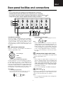
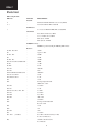
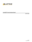
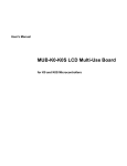
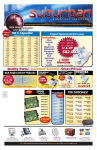
RDA-7
SERVICE MANUAL
Ref NO. 3651
May 2000
Seven Channel Amplifier
RDA-7
Silver model
UPP 230 V AC
UDT 120 V AC
UPT
230 V AC
SAFETY-RELATED COMPONENT
WARNING!!
COMPONENTS IDENTIFIED BY MARK
TABLE OF CONTENTS
1
2
3
4
5
7
8
16
18
19
20
22
ON THE
SCHEMATIC DIAGRAM AND IN THE PARTS LIST ARE
CRITICAL FOR RISK OF FIRE AND ELECTRIC SHOCK.
REPLACE THESE COMPONENTS WITH ONKYO PARTS
WHOSE PART NUMBER APPEAR AS SHOWN IN THIS
MANUAL.
MAKE LEAKAGE-CURRENT OR RESISTANCE MEASUREMENTS TO DETERMINE THAT EXPOSED PARTS
ARE ACCEPTABLY INSULATED FROM THE SUPPLY
CIRCUIT BEFORE RETURNING THE APPLIANCE TO
1
Cover page
Specifications, Supplied accesories
Unpacking abd storing the packing materials
Front panel
Rear panel
Chassis-exploded view
Parts list
Screws
Adjustment procedures
Pcboard
Primary connections
Circuit diagrams
RDA-7
Specifications
AMPLIFIER SECTION
Number of channels:
7
Power:
150 watts per channel min. RMS at 8 ohms, 2 channels
driven from 20 Hz to 20 kHz with no more than 0.1 % total
harmonic distortion.
300 watts per channel min. RMS at 4 ohms, 2 channels
driven at 1 kHz with no more than 0.1 % total harmonic
distortion.
Frequency response @ -3 dB: 3.5 Hz - 250 kHz
Input Impedance:
47 kohm each phase
Input signal for max output power:
1.2 V
Input Sensitivity (Unbalanced):
100 mVrms
Input Sensitivity (Balanced): 200 mV
THD:
0.03 %(20 Hz to 20 kHz)
Damping Factor:
40 at 8 ohm
Power consumption
USA, Canada and some Asian model:
15 A
Other models:
10 A
Rated Speaker Impedance:
GENERAL
Power Supply:
Dimensions (W × H × D):
Weight:
4 ohms
AC 120 V, 60 Hz
AC 230 V, 50 Hz
AC 220 V, 50/60 Hz
450 × 195 × 596 mm
17-11/16" × 7-11/16" × 23-7/16"
51.0 kg, 112.4 lbs.
Specifications and features are subject to change without
notice.
Power supply and voltage vary depending on the area in
which the unit is purchased.
Supplied accessories
Instruction Manual
Check that the following accessories are supplied with the RDA-7.
RDA-7
Power cord
Poly bag
Power cord × 1
The power cord may differ
depending on the region.
Inner carton
2
RDA-7
Unpacking and storing the packing
materials
Unpacking
When unpacking the RDA-7, be sure to remove all
accessories from the cardboard box and then check
that all are included and none are missing.
Inner carton
Removing the RDA-7
After removing the RDA-7, carefully inspect it to make
sure that it has not been damaged during the shipping
processes. If damaged, contact an Onkyo service
station or representative immediately. Also, take down
the name of the carrier in case it is necessary to obtain
compensation from the carrier service.
Storing the packing materials
After unpacking, store the cardboard box and packing
materials in a safe place; do not throw them away. If
you are to transport the RDA-7 at a later date, you will
need this cardboard box and the packing materials.
The RDA-7 is very heavy and may become damaged if
it is transported in a different box.
Outer carton
(Shipping carton)
Pad
Poly bag
Pad
Inner carton
3
RDA-7
Front panel facilities
On
Power
On
Standby
Of f
Seven Channel Amplifier
Power
On /
Off
RDA-7
On/Standby
Pressing this switch connects the RDA-7 to the main
Power outlet and the On indicator lights blue. Sound will
be heard after approximately 9 seconds. If you want to
operate the RDA-7 using a 12-volt trigger, connect to
the 12V TRIGGER terminal of a control amplifier or preamplifier and leave the Power switch of the RDA-7 set to
On.
For example, to control the RDA-7 while it is connected
to the RDC-7 AC controller, connect the 12V TRIGGER A
jack of the RDC-7 to the 12V TRIGGER IN jack of the RDA7 with a 3.5-mm (1/8-inch) mini-jack cable.
The RDA-7 is equipped with two indicators to display its
status. If both indicators are off, then the main Power
switch on the front panel is turned off. If the Power switch
is turned on, then one of these indicators will be lit.
On: Lights blue when Power is supplied from the AC
mains Power supply.
Standby: Lights red when no signal is input from the
12V TRIGGER IN terminal and the RDA-7 is in the
Standby state.
Note:
If the Power switch is pressed and neither indicator lights,
check that the Power cord is properly connected and
that a fuse has not blown. If the indictors still do not light,
turn off the RDA-7, disconnect the Power cord, and
contact an Onkyo service station or representative.
If the On indicator lights blue and the Standby indicator
flashes red, the protection circuitry of the RDA-7 has
activated. The protection circuitry activates if a
problem such as a speaker cord shorting or the
temperature of the RDA-7 rising excessively occurs. Turn
off the RDA-7, remove the cause of the problem, and
then turn the RDA-7 back on. If the problem is still not
solved, turn off the RDA-7, disconnect the power cord,
and contact an Onkyo service station or representative.
If a plug is connected to the 12V TRIGGER IN jack:
The signal reaches the 12V TRIGGER, the On indicator
lights blue. When there is no signal at the 12V TRIGGER,
the Standby indicator lights red.
4
RDA-7
Rear panel facilities and connections
Caution
• Do not connect the Power cord until you have finished all other connections.
• Read the instructions that came with the other components you are connecting.
• Do not make connections to input or output jacks while the RDA-7 is turned on (Power
• Always turn the volume of the pre-amplifier down before turning on the RDA-7.
SURROUND BACK
RIGHT
INPUT
SELECT
OUTPUT
SURROUND
RIGHT
RIGHT
INPUT
SELECT
OUTPUT
CENTER
INPUT
SELECT
INPUT
SELECT
OUTPUT
SURROUND
LEFT
LEFT
INPUT
SELECT
OUTPUT
SURROUND BACK
LEFT
INPUT
SELECT
OUTPUT
on).
INPUT
SELECT
OUTPUT
OUTPUT
SPEAKER IMPEDANCE
4 OHMS MIN. PER EACH
SPEAKER TERMINAL
FUSE
AC INLET
12V TRIGGER
IN
This unit comprises 7 independent power amplifiers,
each being capable of reproducing the same quality
sound through its channel. Note that you should
connect an input source and a speaker to each
channel in use. For channels that are not in use, we
recommend that you do not connect any input source
or speaker.
RDA-7
Note:
• When using this balanced connection for a specific
channel between the pre-amplifier and RDA-7, set
the INPUT SELECT switch to the XLR input side to select
balanced input. Next, use high-quality cables and
connect the balanced output from the pre-amplifier
to the corresponding balanced input on the RDA-7.
• Do not connect anything to the RCA-type audio
input jack.
Balanced Input (XLR terminal)
Connect controllers or pre-amplifiers with balanced
outputs for high-quality sound.
Unbalanced Input (single end RCA input)
2. non-inverting (+)
1
MODEL NO.
2. Disconnecting the input terminal
Pull out the connection cord while holding down the lever.
Push
Precaution for connection
2
SEVEN CHANNEL AMPLIFIER
OUT
1. GND
Connect controllers or pre-amplifiers with single-ended
outputs for high-quality sound.
3. inverting (-)
Note:
• When using this single-ended connection for a
specific channel between the pre-amplifier and
RDA-7, set the INPUT SELECT switch to the RCA input
side to select single-ended input. Next, use highquality cables and connect the single-ended output
from the pre-amplifier to the corresponding singleended input on the RDA-7.
• Do not connect anything to the balanced input jack.
3
Connector ground terminal: Chassis grounded
The pin assignments for this terminal are given above.
This pin assignment conforms to the standard adopted
by the Audio Engineering Society. Refer to the
instruction manual supplied with the pre-amplifier and
verify that its output terminal is compatible with the pin
assignments for this terminal. If it does not, wire it so that
the output pins connect with the proper input pins.
Input terminal
1. Connecting the input terminal
Match the pins and insert the terminal until you hear a
“click.” Ensure that it is secure by gently pulling it.
INPUT SELECT
/
This switch is located between the balanced input and
single-ended RCA input for each channel. Use this
switch to select the input type for its channel.
Note:
• Do not change the INPUT SELECT switch setting when
the RDA-7 is turned on.
5
RDA-7
Rear panel facilities and connections
• Make sure that connections have been made only
to the inputs selected with the INPUT SELECT switches
and nothing is connected to the other ones.
Warning
Before replacing the fuse or making any electrical
connections, always turn off the Power and disconnect
the Power cord.
+ OUTPUT –
(Speaker output and binding post)
12V TRIGGER IN/OUT
The RDA-7 is equipped with high-current binding posts
for use at output terminals to the speaker system. To
obtain the best in sound quality from the RDA-7, we
recommend the use of high-quality speaker cables.
For each channel, connect the negative (or black)
output post to the negative (or black) input terminal of
the speaker and the positive (or red) output post to the
positive (or red) input terminal of the speaker.
Make the connections following the procedure given
below.
1. Strip away 15 mm (5/8 inch) of wire insulation.
2. Twist wire ends very tight.
3. Unscrew
1
2
15 mm
(5/8 inch)
4. Insert wire
5. Screw
3
4
5
Connect the 12V TRIGGER IN jack to control amplifiers
that have a 12V TRIGGER output jack, such as the RDC7. This jacks works on between 5 to 12 volts DC. With the
Power switch of the RDA-7 set to On, you can switch the
RDA-7 between the on and Standby states with
operations at the control amplifier.
If you want another component to be activated by
turning on and off the control amplifier connected to
the 12V TRIGGER IN jack of the RDA-7, then connect the
12V TRIGGER input jack of that component to the 12V
TRIGGER OUT jack of the RDA-7. In this state, even if the
RDA-7 is turned off, the signal from the control amplifier
passes through the RDA-7 and goes out the 12V
TRIGGER OUT jack. Daisy chaining is also possible using
these jacks.
Use φ3.5-mm (1/8-inch) monaural-type mini-jack
connectors. The tip polarity of the connectors are as
shown below.
5-12 volts,
positive tip
polarity
AC INLET
Plug the supplied Power cord into this AC INLET and then
into the Power outlet on the wall,
Be sure to read “Phasing your speaker system” and
“Speaker ratings” on the following page.
AC INLET
Caution
• Do not connect any devices other than speakers to
these terminals. Also, never short-circuit the output
from these terminals.
• Be sure not to mistake the positive and negative
outputs or the left and right speakers. Doing so will
result in an unnatural sound space.
• Only connect speakers with an impedance of 4
ohms or greater. If a speaker with an impedance of
less than 4 ohms is connected, it may damage the
RDA-7.
• Do not connect more than one speaker cable to
one output terminal. Doing may damage the RDA-7.
Power cord (supplied)
To an AC wall outlet
• Do not use a Power cord other than the one supplied
with the RDA-7. The Power cord supplied is designed
for use with the RDA-7 and should not be used with
any other device.
• Never have the Power cord disconnected from the
RDA-7 while the other end is plugged into the wall
outlet. Doing so may cause an electric shock. Always
connect by plugging into the wall outlet last and
disconnect by unplugging from the wall outlet first.
Fuse
The RDA-7 uses a 250V AC slow-blow (time lag) main
fuse. To replace the fuse, insert a coin or similar object
into the groove, turn it to the left, and remove the fuse.
Replace only with the same type and same rating. The
correct fuse rating will differ depending on the voltage
of your set as given here.
120V:T15A/250V
220V/230V/240V:T10A/250V
Ground
If connecting the unit to another equipment causes
noise such as a hum, you may improve the reproduced
sound quality by connecting this terminal to the
grounding terminal of the connected equipment with a
lead wire.
6
RDA-7
CHASSIS-EXPLODED VIEW
Top Cover
Amp Module
Front Panel Assembly
Chassis
7
RDA-7
Parts List
RDA-7 Amp Module
REF. NO.
11
11-1
PART NO.
Heatsink
-
DESCRIPTION
5
PCB Bracket
-
6-32x3/8, Pan Hd Phil SEMS, Blk, Screw(PCBB)
SP terminal
-
Nut, Washer included (21-0062)
Cover 21-0062, CL159706YA
Wire (Red), 14AWG
Wire (Black), 14AWG
M3X6, Pan Hd Phil, BLACK oxide, Screw(PCBH)
Standoff 4.5M3X8, BR517109.0-00
PCB(RDA-7-010-C)
TERM: Lug solder #6, Mfg #21 ERICK (JMP 14-2014)
R1, R85, R77, R84
R2
R3, R17, R49
R4
R5, R81, R83
R67, R75, R76, R78,R80,R82,R6
R7, R8
R9, R10
R11, R12
R13, R15
R14,R16,R41,R42,R26,R27,R47
R18, R31, R38, R64
R19, R20, R21, R22
R23
R24
Resistors
-
R25, R28
R29, R33
R30, R32, R37, R39, R51, R52
R34, R35
R36, R40
R43, R44
R45
R46
-
R48
R50
R53, R54
R55
-
R57 - R62
R63
(47-0089)
-
30.1K
replace to VR8
2.00K
110K
10.0K
100K
13.0K
6.49k
16k/2W
47k
100 Ohm
5.62k
43.2k
147k
Trimpot Single Turn 50k
50k Bourns 3386C
215 Ohm
2.15k
47 Ohm
619 Ohm
68.1 Ohm
10k, 1/2W
562 Ohm
Trimpot 25 Turn 500 Ohm
Bourns 3296X
158k
1k
12k
215 Ohm
0.22 Ohm, 3W, Wirewound (8-21-00)
Pecker, Non-Inductive
10 Ohm, 3W, Wirewound
Non-Inductive
8
RDA-7
REF. NO.
R65
R66
R68
R69, R72, R73
R70
R71
R74
R86
R87, R88
R90, R91
R92
R93
PART NO.
-
DESCRIPTION
4.02k
1k
562 Ohm
215k
261k
562k
348k
7.5k
10 Ohm
1k
Do Not Load
Zero Ohm Jumper
Tube
Do Not Load
R95, R96
-
C1, C2
C3 - C6 (15-0051)
C7, C9, C40
Capacitors
-
C8, C10
C11, C12
-
C13, C14
C15
-
C17, C20
C18, C19
C21
C22, C23
C24, C25
C26
C27
C28
C29
C30, C31, C35, C39, C45
C32, C33, C34
C36
C37
C41
C42
C38
-
L1
Inductors
-
F3, F4
Fuses
-
Littelfuse Pico II R251 015, F837-ND
CR1, CR2
12
12-1
Semiconductors
-
Rectifier Bridge 10A
5-40x1/2, Socket Hd Cap, Blk (25-0052), Screw(TRM)
Washer, Square Cone #6x.312, 25-0048
0.01uF ATI 15-0054, AC Ceramic
10,000uF/ 80V LP5 -80V103MS57, Elna
100uF/100V, Alum. axl
BC 2222 021 90532
0.47uF/100V E1474, Polyester
1uF/50V Tant., P2073-ND or Equiv.
3.3uF/100V EF1335-ND 15-0034, Polyester
220uF/50V Radial 10x16mm, EL
P6269-ND
10uF/100V EF1106-ND, Polyester
1000pF/50V P3102-ND or Equiv., Film
3.3uF/100V EF1335-ND 15-0034, Polyester
6.8pF/50V Axial, Cer.
22p/ 100V Axial, Cer.
0.1uF/50V P4593-ND, Film
0.01uF/50V RA, 103, Cer.
1000pF/50V Axial, Cer.
4.7uF/25V, Tant
.01uF/50V, Axial, Cer.
.1uF/50V Axial, Cer.
47uF/25V, 5mm, radial, P6238-ND, EL
10pF 50V Axial , Cer.
0 33uF 10V Radial P6212-ND, Alum.
2.2uF 100V Radial P6290-ND, Alum.
100pF/50V, Poly,
Load 16 Gage Bare Wire Jumper
Nylon Tube
9
RDA-7
REF. NO.
CR3, CR4
CR6, CR7, CR8, CR10,
CR11, CR12
CR9
CR13
VR1
VR2 - VR5, VR8
VR6, VR7
Q1
13
13-1
13-2
13-3
Q2
13
13-2
13-3
13-4
Q3
Q4
Q5
13
13-2
13-3
13-4
Q6, Q7
Q8
Q9
Q10
Q11
13
13-1
13-2
13-3
Q12
13
13-1
13-2
13-3
Q13, Q14
13
13-2
13-3
PART NO.
87643008
871130
87643008
871130
28170075
-
DESCRIPTION
LED T-1 3/4 Green
Diode Switching 1N4150 or
1N4148
LED T-1 Red (24-5007)
DIP Bridge 1A 400V
Zener 30V 400mW Axial, 1N5256B
Zener 24V 400mW Axial, 1N5252B
Zener 12V 400mW Axial, 1N5242B
IRF620, MOSFET or
IRF621
5-40x3/8(Q1), Socket Hd Cap, Blk (25-0033), Screw(TRS)
Nut(Q1), Hex KEP, 5-40 Zinc
W3x8F(BC), Washer(Q1)
SW-3, Spring Washer(Q1)
IRF540
5-40x3/8(Q2), Socket Hd Cap, Blk (25-0033), Screw(TRS)
W3x8F(BC), Washer(Q2)
SW-3, Spring Washer(Q2)
TOSHIBA AC331, Bush(Q2)
Sheet(Q2)
2N5401
87643008
871130
28170075
87643008
871130
87643008
871130
87643008
871130
2N5551
IRF5210 or
IRF9540N
5-40x3/8(Q5), Socket Hd Cap, Blk (25-0033), Screw(TRS)
W3x8F(BC), Washer(Q5)
SW-3, Spring Washer(Q5)
TOSHIBA AC331, Bush(Q5)
Sheet(Q5)
2SC3381
2SA1349
2N5550
2N5400
2SA1837
5-40x3/8(Q11), Socket Hd Cap, Blk (25-0033), Screw(TRS)
Nut(Q11), Hex KEP, 5-40 Zinc (25-0050)
W3x8F(BC), Washer(Q11)
SW-3, Spring Washer(Q11)
Heatsink(Q11), Thermalloy 7020B
2SC4793
5-40x3/8(Q12), Socket Hd Cap, Blk (25-0033), Screw(TRS)
Nut(Q12), Hex KEP, 5-40 Zinc
W3x8F(BC), Washer(Q12)
SW-3, Spring Washer(Q12)
Heatsink(Q12), Thermalloy 7020B
MJF15030
5-40x3/8(Q13,Q14), Socket Hd Cap, Blk (25-0033), Screw(TRS)
W3x8F(BC), Washer(Q13,Q14)
SW-3, Spring Washer(Q13,Q14)
10
RDA-7
REF. NO.
Q15
13
13-2
13-3
Q16, Q18, Q20
12
12-1
Q17, Q19, Q21
12
12-1
Q23, Q24
U1
U2, U3
U4
U5, U10
U6
U7
U8
U9
J1
J2
7
J3
P1
TP1,2
S1
TS1
PART NO.
87643008
871130
-
DESCRIPTION
MJF15031
5-40x3/8(Q15), Socket Hd Cap, Blk (25-0033), Screw(TRS)
W3x8F(BC), Washer(Q15)
SW-3, Spring Washer(Q15)
2SC3281
5-40x1/2, Socket Hd Cap, Blk (25-0052), Screw(TRM)
Washer(Q16,Q18,Q20), Square Cone #6x.312, 25-0048
Sheet(Q16,Q18,Q20)
2SA1302
5-40x1/2(Q17,Q19,Q21), Socket Hd Cap, Blk (25-0052), Screw(TRM)
Washer(Q17,Q19,Q21), Square Cone #6x.312, 25-0048
Sheet(Q17, Q19, Q21)
MPS2222A (PN2222A)
Voltage Regulator LP2951CN
Voltage Regulator LM317L TO-92
Voltage Reference LM385Z
Optocoupler Single PS2502-1
Dual Comparator TLC372CP
Dual D Flip-Flop CD4013BCN
Triple 3-Input NOR CD4025BCN
TLC555 8pin DIP
Connectors
-
AMP 643416-1 Loaded From Ckt Side(Cut necessary)
A-Ser. XLR NC3FAHL-2 Circuit Side (Groud Cut is necessary)
#4x.500(J2), Pan HD Phil TypeA, Blk (25-0049), Screw(DIN)
RCA PC Board Mount Rt Angle Ckt Side(Use one nut)
Washer(J3), 5610-166-62
AMP 103669-1
Switches
-
NKK:NKKM2022S2A2G30
Thermal Switch UP71 95 Deg.C
Cushion
11
RDA-7
RDA-7 AC PCB Module (RDA-7-020-B)
Ref. No.
Parts Number
10
-
Description
M3x0.5, 12mm, Pan Hd Phil Nickel Pltd, Screw(LEDP)
R1, R4, R13
R2
R3
R5, R7
R6, R12
R8, R11
R9
R10
Resistors
-
10.0K
1k
5.62k
22k
2.15k
100K
215k
16.2K
C1
C2, C4
C3
C5
C6
C7
Capacitors
-
1000uF/16V, 10x20mm, radial, P6231ND, EL
1uF/50V Tant. P2073-ND or Equiv.
47uF/25V, 5mm, radial, P6238-ND, EL.
0.1uF 50V Axial, Cer.
2.2uF/25V, Tant.
0.01uF 50V Axial, Cer.
CR1
CR2, CR3
Semiconductors
-
1A, 400V, DIP (48-0011), Rect., Bridge
1N4150, Diode Switching or
Q1, Q2
U1
-
1N4148
LED T-1 3/4 Blue
Tube
LED T-1 3/4 Red
Tube
MPS2222A
TLC555 8pin DIP
F2
Fuses
-
Littelfuse Pico II R251 001
T1
Transformer
-
Microtran MT3101
K1, K2 (51-0009)
Relays
-
Song Chuan 821-W-1A-C
Connectors
-
AMP Fast-On, male, 63824-1
AMP 4-Pos. Pin Header 103908-3
Terminal Block, 16 Position,
SSB6FP160201NNNN
USHAPE
SCREW6-32x3/8
CR4
CR5
P1-P10 (25-0032)
P11
TB1
FASTON USHAPE
F826-ND
Inrush Current Limiter PCB Module (RDA-7-030-A)
Ref. No.
Parts Number
Description
R1 ~ R4
2.5 Ohm KC003L-ND Or Equiv.
P2, P3 (25-0032)
AMP Fast-On, male, 63824-1
14
6-32x3/8, Pan Hd Phil SEMS, Nickel Pltd, Screw(GROU)
36905
Standoffs, 1/4Hex 6-32x1-1/4, Brass, Nickel Pltd
12
RDA-7
Transformer Assy
Ref. No.
Shroud
Ref. No.
9
L Bracket
Ref. No.
9
12V trigger Assembly
Ref. No.
Conduit
Ref. No.
9
AC Inlet Assembly
Ref. No.
6
Parts Number
-
Description
Transformer, 4Ch
Bushing, Xfmer, 94HB Inserted by ATI
Transformer, 3Ch
Bushing, Xfmer, 94HB Inserted by ATI
Connector, transformer sec., AMP: 350779-1 (UL94-V0)
TUBE
Bolt, Xfmer 3/8-16x3.5
Nut, 3/8-16, ATI
25-0012
Washer, Xfmer, ATI
25-0013
Washer, Rubber, Xfmer, ATI
Parts Number
-
Description
Shround
M4x0.7 8mm, Flat Hd, Blk, Screw(COV)
Parts Number
-
Description
L Bracket
M4x0.7 8mm, Flat Hd, Blk, Screw(COV)
Parts Number
-
Description
Connector to AC 4 pin, AMP103958-3 Molex 50-57-9404 (21-0049)
Wire BLK
Wire WHT
Wire RED
Wire GRN
Mini Jack
Nut(Mini jack)
Wire WHT
Wire BLK
Wire RED
Wire BLK
Wire RED
Tube, 26AWG 25"
Connector to Amp 2 pin, AMP103958-1(ATI 21-0033)Molex 50-57-9402
Parts Number
-
Description
Conduit
-
M4x0.7 8mm, Flat Hd, Blk, Screw(COV)
Parts Number
-
Description
AC Inlet, UL approved (Mouser161-0707-1-250)
Wire(Green/Yellow), AWG14
Nut( GROND), JMP 16-1014
4-40x1/2, Flat Hd , Blk (25-0025), Screw(INLE)
13
RDA-7
REF. NO.
6-1
Chassis
REF. NO.
8
9
9
14
PART NO.
-
DESCRIPTION
Nut, HEX KEP 4-40 Zinc, (25-0030)
Wire(Blk 5")
Fuse Holder, UL/CSA approved(Schurter 0031 1699)
Wire(White)
Wire(Blk)
Tube
PART NO.
29360778
-
DESCRIPTION
Chassis (UDD,UPP,UJJ,UGT)
Serial Number Label
Rubber Feet, ATI 25-0164
10-32x3/4, ATI, Screw(FOOT)
M4x0.7 8mm, Flat Hd, Blk, Screw(COV)
Top Cover
M4x0.7 8mm, Flat Hd, Blk, Screw(COV)
Label(Flash)
Label for Ground
6-32 x 3/8, Pan Hd Phil SEMS, Nickel Pltd, Screw(GROU)
PART NO.
27212183
28325734
28198908
27268013
82143006
DESCRIPTION
Front Panel Assembly
Front Bracket with pemnut
10-32x1/4, Button Hd Cap, Blk, Screw(FBRA)
Switch plate
Power Switch, TV-5, UL marking, VDE, SEMKO, 5A
Alpha: PS-1108-512-L
4-40x1/4(POW SW), Pan Hd, Phil, Zinc, Screw(PSW)
Knob AS (POW)
Wire(Blk)
4-40x1/4, (POW ASS'Y), Phil Pan Hd, SEMS, Zinc, Screw(SWPL)
10-32x3/8, Pan Hd, Phil, Ni, Screw(FCHA)
Facet(1)
Guide(Power)
3P+6FN(BC), Screw (Guide (Power))
PART NO.
-
DESCRIPTION
Inner Carton
Outer Carton
Destination label
29361573
29100097-1A
PAD(L)
PAD(R)
Poly Bag
Warning Label
PE-LD label
Poly Bag(Manual)
Front Panel Module
REF. NO.
3
1
2
4
Shipping Carton Assembly
REF. NO.
14
RDA-7
RDA-7 AC PCB Module Jumpers
REF. NO.
PART NO.
Others
REF. NO.
PART NO.
29342947
29342949
29342948
29342950
253303HIT
29365086
29365082A
29362620
29362621
29362622
29095865
DESCRIPTION
L, L <UDD, UDT, UJJ>
H <UPP, UPT, UGT>
DESCRIPTION
Chassis(UDD)
<UDD,UDT>
Chassis(UPP)
<UPP, UPT>
Chassis(UGT)
<UGT>
Chassis(UJJ)
<UJJ>
Plug for binding post, Cliff RED CL159777 <UPP, UPT, UGT>
Plug for binding post, Cliff Blk CL159778 <UPP, UPT, UGT>
Fuse (43-0015), 120: LF314 015 15A 250V, UL/CSA <UDD, UDT, UJJ>
Fuse (43-0004), 230: LF314 010, 10A250V UL/CSA <UPP, UPT, UGT>
Instruction Manual, E <UDD,UDT, UPP, UPT, UGT>
Instruction Manual, T <UDT, UPT, UGT>
Instruction Manual, G,D,SW,F,S,I <UPP>
Instruction Manual, J <UJJ>
AC Cord, 120: Tumbler: 3271JW46 <UDD, UDT>
AC Cord, 230: Unicable:8150-25M-BB <UPP, UPT, UGT>
AC Cord <UJJ>
Warranty Card <UDD>
Warranty Card <UJJ>
UPC Label <UDD>
EAN Label <UDT, UPP, UPT, UGT>
POS Label <UJJ>
Sheet(Integra) <UDD>
15
RDA-7
SCREWS
14
GROU
14 - 1
16
RDA-7
13 - 2
13 - 3
13 - 1
11
11 - 1
13
13
13 - 2
13 - 3
13 - 4
13
13 - 2
13 - 3
6
6-1
17
12
12 - 1
RDA-7
ADJUSTMENT PROCEDURES
Channel Test
4. Connect a DC voltmeter to the test points TP1 and TP2 and
adjust the voltage to 4mV using the R46 BIAS adjustment
trimpot.
5. Allow the channel to warm up for 30 minutes, adjusting the
bias every ten minutes.
6. Measure the output DC voltage and adjust it as close to zero
as possible using the R24 trimpot.
1. Connect the assembled channel to the power transformer and
turn it ON.
2. After about 9 seconds the two green LED's should turn ON
3. Measure the following voltages and make sure they are within
the specifications: For all these measurements connect the DC
voltmeter negative lead to the bottom lead of the VR8 zener
diode.
C7 (+)
70V +/- 3V
C9 (-)
-70V +/- 3V
L1
0V +/- .1V
Main Chassis Test
1. Assemble the chassis/power supply and configure it for right
line voltage.
2. Plug it into the power line.
3. Turn the unit ON. The blue ON LED should come ON.
4. Red Fault/Standby LED should be flashing.
5. Turn the unit OFF and plug a remote control plug into the
Remote IN jack.
6. Turn the unit ON. The Red Standby LED should be ON.
7. Apply 12V to the remote control plug. The unit should turn
ON, the blue LED should be ON and the red LED flashing.
8. Measure the secondary voltages on all power cables going to
the channels. Each secondary should read 50VAC +/- 2VAC.
Final Assembly Test
1. Install all channels in the chassis and turn the unit ON. All
green LED's should come ON after about 9 seconds.
2. Check bias currents on all channels and adjust if necessary.
3. Allow the unit to warm up for 30 minutes, adjusting the bias
currents every ten minutes.
4. Adjust the DC output voltage as close to zero as possible on
each channel.
18
Circuit side view from component side
Pcboard
Component side view from circuit side
RDA-7
19
RDA-7
RDA-7 Primary Connections For Different Voltages
AC Board Jumpers
For voltages in the 100V - 120V range, install the two jumpers marked L
For voltages in the 200V - 240V range install the single jumper marked H
Main Transformer Jumpers
The following connections should be made for different line voltages:
200V:
100V:
K1-3 to BL1-4
BL1-2 to BL1-3
K2-3 to BL1-12
BL1-10 to BL1-11
K1-3 to BL1-4,
P7 to BL1-3
P2 to BL1-2
K2-3 to BL1-12,
P8 to BL1-11
P3 to BL1-10
220V:
K1-3 to BL1-6
BL1-2 to BL1-5
K2-3 to BL1-14
BL1-10 to BL1-13
110V:
K1-3 to BL1-6,
P7 to BL1-5
P2 to BL1-2
K2-3 to BL1-14,
P8 to BL1-13
P3 to BL1-10
230V:
K1-3 to BL1-6
BL1-2 to BL1-7
K2-3 to BL1-14
BL1-10 to BL1-15
120V:
K1-3 to BL1-8,
P7 to BL1-7
P2 to BL1-2
K2-3 to BL1-16,
P8 to BL1-15
P3 to BL1-10
240V:
K1-3 to BL1-8
BL1-2 to BL1-7
K2-3 to BL1-16
BL1-10 to BL1-15
20
RDA-7
1
2
3
4
5
6
7
8
9 10 11 12 13 14 15 16
BL1
P8
P7
P2
P3
K1-3
K2-3
K1-4
K2-4
P4
P1
P9 P10
Inrush Current Limiter Board
(RDA-7-030)
Low
High
Jumpers
AC PCB Module (RDA-7-020)
21
L
L
H
RDA-7
SCHEMATIC DIAGRAMS
POWER SUPPLY
22
RDA-7
DRIVER CIRCUIT
23
RDA-7
OUTPUT STAGE AND PROTECTION
24
RDA-7
PROTECTION
25
RDA-7
AC BOARD
26
RDA-7
PROTECTION WIRING
27
RDA-7
Integra Research Division of
ONKYO CORPORATION
Sales & Product Planning Div. : 2-1, Nisshin-cho, Neyagawa-shi, OSAKA 572-8540, JAPAN
Tel: 072-831-8111 Fax: 072-833-5222 http://www.onkyo.co.jp/
Integra Research Division of
ONKYO U.S.A. CORPORATION
18 Park Way,Upper Saddle River, NJ 07458, U.S.A.
Tel: 201-785-2600 Fax: 201-785-2650 E-mail: [email protected]
ONKYO EUROPE ELECTRONICS GmbH
Industriestrasse 20, 82110 Germering, GERMANY
Tel: 089-849-320 Fax: 089-849-3265 E-mail: [email protected]
ONKYO CHINA LIMITED
Units 2102-2107, Metroplaza Tower I, 223 Hing Fong Road, Kwai Chung,
N.T., HONG KONG Tel: 852-2429-3118 Fax: 852-2428-9039
0M3646
28
N0600
Printed in Japan