1
Diesel Injection Pump
SERVICE MANUAL
Common Rail System for ISUZU
4HK1 / 6HK1 Type Engine
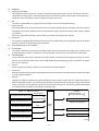
OPERATION
February, 2004
00400056E
FORWARD
To meet the high pressurization requirements for the engine to deliver cleaner exhaust gas emissions, lower fuel
consumption and reduced noise, advanced electronic control technology is being adopted in the fuel injection system.
This manual covers the electronic control model Common Rail system with HP3/HP4 pump for the ISUZU 4HK1/6HK1
type engines which are used to ELF and GM 560 series respectively. Complex theories, special functions and
components made by manufacturers other than DENSO are omitted from this manual.
This manual will help the reader develop an understanding of the basic construction, operation and system configuration
of the DENSO manufactured components and brief diagnostic information.
TABLE OF CONTENTS
1. Product Application . . . . . . . . . . . . . . . . . . . . . . . . . . . . . . . . . . . . . . . . . . . . . . . . . . . . . . . . . . . . . . . . . . . . . . . . . . . . . . . . . . . . 1
1-1. Application . . . . . . . . . . . . . . . . . . . . . . . . . . . . . . . . . . . . . . . . . . . . . . . . . . . . . . . . . . . . . . . . . . . . . . . . . . . . . . . . . . . . . . . 1
1-2. System Components Parts Numbers . . . . . . . . . . . . . . . . . . . . . . . . . . . . . . . . . . . . . . . . . . . . . . . . . . . . . . . . . . . . . . . . . . 1
2. Outline . . . . . . . . . . . . . . . . . . . . . . . . . . . . . . . . . . . . . . . . . . . . . . . . . . . . . . . . . . . . . . . . . . . . . . . . . . . . . . . . . . . . . . . . . . . . . . . 2
2-1. Outline of System . . . . . . . . . . . . . . . . . . . . . . . . . . . . . . . . . . . . . . . . . . . . . . . . . . . . . . . . . . . . . . . . . . . . . . . . . . . . . . . . . . 2
2-2. Outline of System . . . . . . . . . . . . . . . . . . . . . . . . . . . . . . . . . . . . . . . . . . . . . . . . . . . . . . . . . . . . . . . . . . . . . . . . . . . . . . . . . . 4
2-3. Fuel System and Control System . . . . . . . . . . . . . . . . . . . . . . . . . . . . . . . . . . . . . . . . . . . . . . . . . . . . . . . . . . . . . . . . . . . . . 5
3. Construction and Operation . . . . . . . . . . . . . . . . . . . . . . . . . . . . . . . . . . . . . . . . . . . . . . . . . . . . . . . . . . . . . . . . . . . . . . . . . . . . . 6
3-1. Description of Main Components . . . . . . . . . . . . . . . . . . . . . . . . . . . . . . . . . . . . . . . . . . . . . . . . . . . . . . . . . . . . . . . . . . . . . 6
3-2. Description of Control System Components . . . . . . . . . . . . . . . . . . . . . . . . . . . . . . . . . . . . . . . . . . . . . . . . . . . . . . . . . . 22
3-3. Various Types of Control . . . . . . . . . . . . . . . . . . . . . . . . . . . . . . . . . . . . . . . . . . . . . . . . . . . . . . . . . . . . . . . . . . . . . . . . . . . 24
3-4. Engine ECU . . . . . . . . . . . . . . . . . . . . . . . . . . . . . . . . . . . . . . . . . . . . . . . . . . . . . . . . . . . . . . . . . . . . . . . . . . . . . . . . . . . . . . 31
1.
Product Application
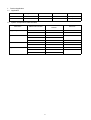
1-1. Application
Vehicle Name
Engine Model
Vehicle model
Exhaust Volume
Reference
ELF
4HK1
N series
5.2L
Direct-Injection
C560 Series
6HK1
GM 560
7.8L
Direct-Injection
1-2. System Components Parts Numbers
Parts Name
Supply Pump
Injector
Rail
Engine ECU
Car Manufacturer Parts
DENSO Parts Number
Reference
Number
294000-0260
8973288860
4HK1
294050-0021
9876020491
6HK1
095000-5351
8976011561
6HK1
095000-5361
8976028031
095000-5471
8973297031
4HK1
095440-0351
8973060632
4HK1
095440-0470
8973230190
6HK1
275800-2801
8151794773
6HK1
275800-2812
8973750190
4HK1
275800-2822
8973750200
-1-
2.
Outline
2-1. Outline of System
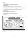
•
The common rail system was developed primarily to cope with exhaust gas regulations for diesel engines, and aimed for
1. further improved fuel economy; 2. noise reduction; and 3. high power output.
A. System Characteristics
• The common rail system uses a type of accumulation chamber called a rail to store pressurized fuel, and injectors that
contain electronically controlled solenoid valves to spray the pressurized fuel into the cylinders.
• Because the engine ECU controls the injection system (including the injection pressure, injection rate, and injection timing), the injection system is unaffected by the engine speed or load.
• This ensures a stable injection pressure at all times, particularly in the low engine speed range, and dramatically decreases the amount of black smoke ordinarily emitted by a diesel engine during start-up and acceleration.
• As a result, exhaust gas emissions are cleaner and reduced, and higher power output is achieved.
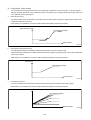
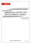
a.
Injection Pressure Control
• Enables high-pressure injection even at low engine speeds.
• Optimizes control to minimize particulate matter and NOx emissions.
b.
Injection Timing Control
Enables finely tuned optimized control in accordance with driving conditions.
c.
Injection Rate Control
Pilot injection control sprays a small amount of fuel before the main injection.
Common Rail System
Optimization, High Pressurization
Optimization
Common Rail System
Speed
Injection Timing
NOx
Conventional
Pump
Particulate
Injection Pressure
Common Rail System
Injection
Pressure
Injection Rate Control
Injection Rate
Injection Timing Control
Pilot Injection
Main
injection
Crankshaft Angle
Injection Quantity Control
Conventional
Pump
Speed
Cylinder Injection
Volume Correction
Speed
Injection Pressure Control
㧝 㧟 㧠 㧞
QD0734E
d.
EGR (Exhaust Gas Recirculation) Control
By recirculating the exhaust gas into the intake side of the engine, the combustion temperature is reduced and NOx is
decreased.
-2-
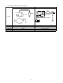
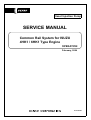
B. Comparison to the Conventional System
Common Rail System
In-line, VE Pump
High-pressure Pipe
Rail
Momentary High Pressure
Timer
TWV
Nozzle
Supply Pump
Usually High Pressure
Delivery Valve
Governor
System
In-line Pump
Feed Pump SCV (Suction Control Valve)
Injector
Fuel Tank
VE Pump
Injection Quantity Control
Pump (Governor)
Engine ECU, Injector (TWV)*1
Injection Timing Control
Rising Pressure
Distributor
Pump (Timer)
Engine ECU, Injector (TWV)*1
Engine ECU, Supply Pump
Injection Pressure Control
Pump
Pump
Dependent upon Speed and Injection Quantity
Engine ECU, Rail
Engine ECU, Supply Pump (SCV)*2
*1 TWV: Two Way Valve *2 SCVSuction Control Valve
-3-
QD2341E
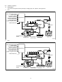
2-2. Outline of System
A. Composition
The common rail system consists primarily of a supply pump, rail, injectors, and engine ECU.
a.
4HK1
Fuel temperature sensor
Vehicle speed
Accelerator opening
Intake air pressure
Intake air temperature
Coolant temperature
Crankshaft position
Cylinder recognition sensor
Engine ECU
Intake airflow rate
Rail
Pressure
limiter
Injector
Rail pressure
sensor
Fuel temperature
sensor
Supply pump
SCV (suction
control valve)
Fuel tank
Q000737E
b.
6HK1
Fuel temperature sensor
Vehicle speed
Accelerator opening
Intake air pressure
Intake air temperature
Coolant temperature
Crankshaft position
Cylinder recognition sensor
Engine ECU
Intake airflow rate
Rail
Pressure
limiter
Injector
Rail pressure
sensor
Fuel temperature
sensor
Supply pump
SCV (suction
control valve)
Fuel tank
Q000523E
-4-
B. Operation
a.
Supply pump (HP3/HP4)
The supply pump draws fuel from the fuel tank, and pumps the high pressure fuel to the rail. The quantity of fuel discharged from the supply pump controls the pressure in the rail. The SCV (Suction Control Valve) in the supply pump
effects this control in accordance with the command received from the ECU.
b.
Rail
The rail is mounted between the supply pump and the injector, and stores the high pressure fuel.
c.
Injector (G2 type)
• This injector replaces the conventional injection nozzle, and achieves optimal injection by effecting control in accordance
with signals from the ECU. Signals from the ECU determine the length of time and the timing in which current is applied
to the injector.
• This in turn, determines the quantity, rate and timing of the fuel that is injected from the injector.
d.
Engine ECU
The engine ECU calculates data received from the sensors to comprehensively control the injection quantity, timing and
pressure, as well as the EGR (exhaust gas recirculation).
2-3. Fuel System and Control System
A. Fuel System
This system comprises the route through which diesel fuel flows from the fuel tank to the supply pump, via the rail, and
is injected through the injector, as well as the route through which the fuel returns to the tank via the overflow pipe.
B. Control System
In this system, the engine ECU controls the fuel injection system in accordance with the signals received from various
sensors. The components of this system can be broadly divided into the following three types: (a.) Sensors; (b.) Engine
ECU; and (c.) Actuators.
a.
Sensors
Detect the engine and driving conditions, and convert them into electrical signals.
b.
Engine ECU
Performs calculations based on the electrical signals received from the sensors, and sends them to the actuators in order
to achieve optimal conditions.
c.
Actuators
Operate in accordance with electrical signals received from the ECU. Injection system control is undertaken by electronically controlling the actuators. The injection quantity and timing are determined by controlling the length of time and the
timing in which the current is applied to the TWV (Two-Way Valve) in the injector. The injection pressure is determined
by controlling the SCV (Suction Control Valve) in the supply pump.
Sensor (*1 : DENSO products)
Actuator
EGR is produced
by other manufactures.
Engine Speed
Crankshaft Position Sensor NE
Injector
Cylinder Recognition
•Injection Quantity Control
•Injection Timing Control
Cylider Recognition Sensor G
Accelerator Position Sensor
Load
Engine
ECU
Supply Pump (SCV)
•Injection Pressure Control
Rail Pressure Sensor (*1)
EGR, Engine Warning Light
Other Sensors and Switches
Q000524E
-5-
3.
Construction and Operation
3-1. Description of Main Components
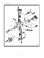
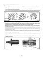
A. Supply Pump (HP3, HP4)
a.
Outline
The supply pump consists primarily of the pump body (cam shaft, ring cam, and plungers), SCV (Suction Control Valve),
fuel temperature sensor, and feed pump.
HP3
SCV
Fuel Temperature Sensor
Q000525E
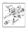
HP4
Fuel Temperature Sensor
SCV
Q000526E
• The two plungers for HP3 or the three plungers for HP4 are positioned vertically on the outer ring cam for compactness.
• The engine drives the supply pump at a ratio of 1:1. The supply pump has a built-in feed pump (trochoid type), and draws
the fuel from the fuel tank, sending it to the plunger chamber.
-6-
• The internal camshaft drives the two plungers, and they pressurize the fuel sent to the plunger chamber and send it to
the rail. The quantity of fuel supplied to the rail is controlled by the SCV, using signals from the engine ECU. The SCV is
a normally opened type (the intake valve opens during de-energization).
Injector
Discharge Valve
Rail
Intake Pressure
Feed Pressure
High Pressure
Return Pressure
Intake Valve
Plunger
Return Spring
Return
SCV
Fuel Overflow
Regulating Valve
Feed Pump
Filter
Fuel Inlet
Camshaft
Intake
Fuel Filter (with Priming Pump)
Fuel Tank
QD0704E
-7-
• Development: HP3
SCV
Plunger
Feed Pump
Pump Body
Fuel Temperature
Sensor
Ring Cam
Regulating
Valve
Drive Shaft
Filter
Plunger
Q000527E
-8-
• Development: HP4
SCV
Plunger
Fuel Temperature
Sensor
Filter
Feed Pump
Ring Cam
Regulating
Valve
Pump Body
Drive Shaft
Plunger
Q000528E
-9-
b.
Supply Pump Internal Fuel Flow
The fuel that is drawn from the fuel tank passes through the route in the supply pump as illustrated, and is fed into the rail.
Supply Pump Interior
Regulating Valve
Feed Pump
Overflow
SCV (Suction Control Valve)
Pumping Portion (Plunger)
Rail
Intake Valve
Fuel Tank
Q000283E
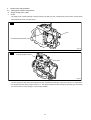
c.
Construction of Supply Pump (in case of HP3 pump)
• The eccentric cam is attached to the cam shaft. The eccentric cam is connected to the ring cam.
Cam Shaft
Eccentric Cam
Ring Cam
QD0706E
• As the cam shaft rotates, the eccentric cam rotates eccentrically, and the ring cam moves up and down while rotating.
Plunger
Eccentric Cam
Ring Cam
Cam Shaft
QD0727E
-10-
• The plunger and the suction valve are attached to the ring cam. The feed pump is connected to the rear of the cam shaft.
Plunger A
Ring Cam
Feed Pump
Plunger B
-11-
QD0728E
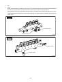
d.
Operation of the Supply Pump
• As shown in the illustration below (in case of HP3 pump), the rotation of the eccentric cam causes the ring cam to push
Plunger A upwards. Due to the spring force, Plunger B is pulled in the opposite direction to Plunger A.
• As a result, Plunger B draws in fuel, while Plunger A pumps it to the rail. In the case of the 4-cylinder engine used with
the HP3 pump, each plunger pumps fuel in a reciprocal movement during the 360° cam rotation.
• Conversely, in the case of the 6-cylinder engine used with the HP4 pump, 3 plungers pump fuel in a reciprocal movement
for each one rotation of the cam.
Suction Valve
Delivery Valve
Plunger A
Eccentric Cam
Ring Cam
SCV
Plunger B
Plunger B: Complete Intake
Plunger A: Begin Intake
Plunger B: Begin Compression
Plunger A: Begin Compression
Plunger B: Begin Intake
Plunger A: Complete Intake
Plunger B: Complete Compression
Plunger A: Complete Compression
QD0707E
< NOTE >
• There are 3 plungers for the HP4.
-12-
B. Description of Supply Pump Components
a.
Feed Pump
• The trochoid type feed pump, which is integrated in the supply pump, draws fuel from the fuel tank and feeds it to the
two plungers via the fuel filter and the SCV (Suction Control Valve).
• The feed pump is driven by the drive shaft. With the rotation of the inner rotor, the feed pump draws fuel from its suction
port and pumps it out through the discharge port.
• This is done in accordance with the space that increases and decreases with the movement of the outer and inner rotors.
Quantity Decrease
Outer Rotor
to Pump Chamber
Quantity Decrease (Fuel Discharge)
Inner Rotor
Intake Port
from Fuel Tank
b.
Discharge
Port
Quantity Increase
Quantity Increase (Fuel Intake)
QD0708E
SCV: Suction Control Valve (Normally open type)
• A linear solenoid type valve has been adopted. The ECU controls the duty ratio (the duration in which current is applied
to the SCV), in order to control the quantity of fuel that is supplied to the high-pressure plunger.
• Because only the quantity of fuel that is required for achieving the target rail pressure is drawn in, the actuating load of
the supply pump decreases.
• When current flows to the SCV, variable electromotive force is created in accordance with the duty ratio, moving the armature to the left side. The armature moves the cylinder to the left side, changing the opening of the fuel passage and
thus regulating the fuel quantity.
• With the SCV OFF, the return spring contracts, completely opening the fuel passage and supplying fuel to the plungers.
(Full quantity intake and full quantity discharge)
• When the SCV is ON, the force of the return spring moves the cylinder to the right, closing the fuel passage (normally
opened).
• By turning the SCV ON/OFF, fuel is supplied in an amount corresponding to the actuation duty ratio, and fuel is discharged by the plungers.
Exterior View of SCV
Cross-section of SCV
SCV
Return Spring
Pump Body
Cylinder
Q000270E
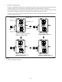
(1)
In case of short time ON duty
-13-
Short time ON duty => large valve opening => maximum intake quantity
Feed Pump
Plunger
SCV
Cylinder
Large Opening
Cylinder
Q000051E
-14-
(2)
In case of long time ON duty
Long time ON duty => small valve opening => minimum intake quantity
Feed Pump
Plunger
SCV
Cylinder
Small Opening
Cylinder
Q000052E
-15-
C. Rail
a.
Outline
• Stores pressurized fuel (0 to 160 MPa {0 to 1631.6 kg/cm2}) that has been delivered from the supply pump and distributes
the fuel to each cylinder injector. A rail pressure sensor and a pressure limiter are adopted in the rail.
• The rail pressure sensor (Pc sensor) detects the fuel pressure in the rail and sends a signal to the engine ECU, the pressure limiter prevents the rail pressure from being abnormally high. This ensures optimum combustion and reduces combustion noise.
For 4HK1
Pressure Sensor
Pressure Limiter
Q000529E
For 6HK1
Pressure Limiter
Pressure Sensor
Q000530E
-16-
b.
Pressure Limiter
• The pressure limiter opens to release the pressure if an abnormally high pressure is generated.
• When the rail pressure reaches approximately 200 MPa (2038 kg/cm2), it trips the pressure limiter (the valve opens).
When the pressure drops to approximately 50 MPa (509.5 kg/cm2), the pressure limiter returns to its normal state (the
valve closes) in order to maintain the proper pressure.
: 4HK1 200 ± 9 MPa
(2038 ± 92 kg/cm2)
: 6HK1 221 ± 9 MPa
(2254 ± 92 kg/cm2)
Valve Open
Valve Close
50 MPa (509.5 kg/cm2)
Q000531E
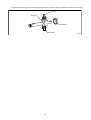
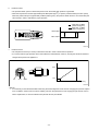
c.
Pressure Sensor
• The rail pressure sensor (Pc sensor) is attached to the rail in order to detect the fuel pressure.
• It is a semiconductor type pressure sensor that utilizes the characteristics of silicon, whereby the electrical resistance
changes when pressure is applied to it.
4.2 V
VC
VOUT
1.0 V
GND
0
200 MPa (2038 kg/cm2)
Q000532E
< NOTE >
• It is necessary to reset the ECU default value using the ISUZU diagnosis tool at the time of supply pump service replacement. In addition, the ECU has a function enabling it to learn the performance of the supply pump at the time of ECU
service replacement, so ensure sufficient time (several minutes) is available.
-17-
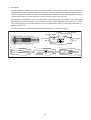
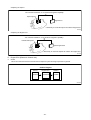
d.
Flow Damper
• The flow dampers are installed at the outlet of rail to damp a pulsation of fuel pressure inside the rail or to cut off the fuel
supply when the fuel leaks in the downstream of flow damper. The fuel is supplied to the injectors through an orifice of
the piston. The pressure pulsation occurring in the rail is damped by a resistive force of the return spring (5) and a passing
resistance of the orifice (2), wherein the piston (4) acts as a damper. (Refer to the picture B)
• Also, the leading end of piston (4) closes an fuel supply port to cut off the fuel supply, if the fuel leak occurs in the injection
pipe or injectors, and the fuel pressure on the downstream side of flow damper supplied through an orifice (2) + resistive
force of return spring (5) do not balance with the fuel pressure applied on the piston (4) surface prior to the orifice (2).
(Refer to the picture C)
• The piston (4) will return when the fuel pressure inside the rail less than 1.0 MPa (10.2 kgf/cm2).
(2) Orifice (3) Slit
(4) Piston
(6) Housing
(5) Return Spring
(1) From Rail
A
B
(7) To Injector
C
Q000742E
-18-
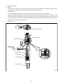
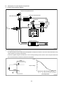
D. Injector (G2 Type)
a.
Outline
The injectors inject the high-pressure fuel from the rail into the combustion chambers at the optimum injection timing,
rate, and spray condition, in accordance with commands received from the ECU.
b.
Characteristics
• A compact, energy-saving solenoid-control type TWV (Two-Way Valve) injector has been adopted.
• QR codes displaying various injector characteristics and the ID codes showing these in numeric form (30 base 16 characters) are engraved on the injector head. The 4HK1/6HK1 engine common rail system optimizes injection volume control using this information. When an injector is newly installed in a vehicle, it is necessary to enter the ID codes in the
engine ECU using the ISUZU Diagnostic tool.
c.
Construction
QR Codes
30 base 16 characters
Solenoid Valve
Control Chamber
Pressurized Fuel
(from Rail)
Command Piston
Nozzle Spring
Pressure Pin
Nozzle Needle
Q000533E
-19-
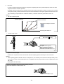
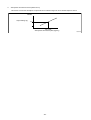
d.
QR Codes
• In order to minimize performance tolerance of injectors at replacing them, QR*1 (Quick Response) codes have been
adopted to enhance correction precision.
• Using QR codes has resulted in a substantial increase in the number of fuel injection quantity correction points, and thus
the injection quantity control precision has improved. The characteristics of the engine cylinders have been further unified, contributing to improvements in combustion efficiency, reductions in exhaust gas emissions and so on.
< NOTE >
• QR code correction points
Injection quantity Q
Pressure Parameter
QR code on the injector connector
Actuating pulse width TQ
Q000670E
•
Location of QR codes
QR Codes (
9.9mm)
ID Codes
(30 alphanumeric figures)
Base 16 characters noting fuel
injection quantity correction
information for market service use.
Q000534E
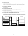
e.
Repair Procedure Changes
• Differences in comparison with the conventional method of replacing injectors assembly are as shown below.
< NOTE >
• When replacing injectors with QR codes, or the engine ECU, it is necessary to record the ID codes (QR codes) in the
ECU. (If the ID codes of the installed injector are not registered correctly, engine failure such as rough idling and noise
will result.)
• New (Injector with QR Codes)
30 base 16 characters noting fuel injection quantity correction
information displaed for market service use
ID Code
Q000535E
-20-
• Replacing the Injector
"No correction resistance, so no electrical recognition capability"
Spare Injector
Engine ECU
* Necessary to record the injector ID codes in Engine ECU
QD1536E
• Replacing the Engine ECU
"No correction resistance, so no electrical recognition capability"
Vehicle-side Injector
Spare Engine ECU
* Necessary to record the injector ID codes in the engine ECU
QD1537E
E. Engine ECU (Electronic Control Unit)
a.
Outline
This is the command center that controls the fuel injection system and engine operation in general.
Outline Diagram
Sensor
Engine ECU
Actuator
Detection
Calculation
Actuation
QD2352E
-21-
3-2. Description of Control System Components
A. Engine Control System Diagram
Intake Air Temperature Sensor
Intake Air Pressure Sensor
Mass Airflow Meter
Inter-Cooler
G2 Injector
EGR Cooler
EGR
Valve
VNT
Controller
VNT Actuator
Coolant
Oxidation Catalyst
Q000536E
a.
Fuel Temperature Sensor (THL)
• The fuel temperature sensor detects the fuel temperature and outputs it to the ECU. The sensor uses a thermistor, which
varies resistance according to temperature.
• As the ECU applies voltage to the thermistor, it uses a voltage resulting from the division of the computer internal resistance and the thermistor resistance to detect the temperature.
VTHL (V)
ECU
5
+5V
4
VTHL
3
Output Voltage
2
1
A-GND
0
THL
-40 -20
-40 -4
0
32
20 40 60 80 100 120 (°C)
68 104 140 176 212 248 (°F)
Fuel Temperature
-22-
Q000106E
b.
Atmospheric Air Pressure Sensor (Built-in ECU)
This sensor converts the atmospheric air pressure into an electrical signal to correct full load injection volume.
VPATM
Output Voltage (V)
3.8
107 {1.09}
Atmospheric Air Pressure (kPa {kg/cm2})
-23-
Q000278E
3-3. Various Types of Control
•
This system controls the fuel injection quantity and injection timing more optimally than the mechanical governor or timer
used in conventional injection pumps.
•
For system control, the ECU makes the necessary calculations based on signals received from sensors located in the
engine and on the vehicle in order to control the timing and duration in which current is applied to the injectors, thus realizing optimal injection timing.
A. Fuel Injection Rate Control Function
The fuel injection rate control function controls the ratio of the quantity of fuel that is injected through the nozzle hole
during a specified period.
B. Fuel Injection Quantity Control Function
The fuel injection quantity control function, replaces the conventional governor function, and controls fuel injection to
achieve an optimal injection quantity based on the engine speed and the accelerator opening.
C. Fuel Injection Timing Control Function
The fuel injection timing control function, replaces the conventional timer function, and controls the fuel injection to
achieve an optimal injection timing according to the engine speed and the injection quantity.
D. Fuel Injection Pressure Control Function (Rail Pressure Control Function)
• The fuel injection pressure control function (rail pressure control function) uses a rail pressure sensor to measure fuel
pressure, and feeds this data to the ECU to control the pump discharge quantity.
• Pressure feedback control is implemented to match the optimal quantity (command quantity) set according to the engine
speed and the fuel injection quantity.
Input Signal (*1 : DENSO products)
Control Output
Accelerator sensor
Fuel Injection Rate Control
NE Sensor
(Crankshaft Position Sensor)
Fuel Injection Quantity Control
TDC Sensor
(Cylinder Recognition Sensor)
Fuel Control Computer
(ECU)
Fuel Injection Timing Control
Rail Pressure Sensor (*1)
Fuel Injection Pressure Control
Various Sensors (*1)
·Water Temperature Sensor
·Fuel Temperature Sensor
·Atmospheric Air Temperature
Sensor etc.
Atmospheric Air
Pressure Sensor
Diagnosis
Q000537E
-24-
E. Fuel Injection Rate Control
a.
Main Injection
Same as conventional fuel injection.
b.
Pilot Injection
• Pilot injection is the injection of a small amount of fuel prior to the main injection.
Main Injection
Pilot Injection
Q000110E
• While the adoption of higher pressure fuel injection is associated with an increase in the injection rate, the lag (injection
lag) that occurs from the time fuel is injected until combustion starts cannot be reduced below a certain value. As a result,
the quantity of fuel injected before ignition increases, resulting in explosive combustion together with ignition, and an increase in the amount of NOx and noise. Therefore, by providing a pilot injection, the initial injection rate is kept to the
minimum required level dampening, the explosive first-period combustion and reducing NOx emissions.
TDC
Combustion
Process
Small Injection Amount
Prior to Ignition
High Injection
Rate
Pilot Injection
Improvement
Injection Rate
Large Pre-mixture
Combustion
(NOx, Noise)
Small Pre-mixture
Combustion
Heat Generation
Rate
Ignition Delay
Q000111E
-25-
F. Fuel Injection Quantity Control
a.
Starting Injection Quantity
The injection quantity is determined based on the engine speed (NE) and water temperature while starting.
Starting Injection Quantity
Water Temperature
Engine Speed
Q000127E
b.
Transient Injection Quantity Correction
When the changes in the accelerator opening are great during acceleration, the increase in fuel volume is delayed to
inhibit the discharge of black smoke.
Injection Quantity
Change in Accelerator Opening
Injection Quantity after Correction
Delay Time
Time
Q000128E
c.
Basic Injection Quantity
• This quantity is determined in accordance with the engine speed (NE) and the accelerator opening.
• Increasing the accelerator opening while the engine speed remains constant causes the injection quantity to increase.
Basic Injection Quantity
Accelerator Opening
Engine Speed
Q000129E
-26-
d.
Injection Quantity for Maximum Speed Setting
The injection quantity is regulated by a value that is determined in accordance with the engine speed.
Injection Quantity for Maximum Speed Setting
Engine Speed
Q000130E
e.
Maximum Injection Quantity
Is determined in accordance with the engine speed and corrected by the coolant temperature signal.
Basic Maximum Injection Quantity
Engine Speed
Q000131E
f.
Amount of Injection Quantity Intake Pressure Correction
Limits the maximum injection quantity in accordance with the intake pressure, in order to minimize the discharge of
smoke when the intake air pressure is low.
Amount of Intake Air Pressure Correction
Engine Speed
-27-
Q000133E
g.
Amount of Injection Quantity by Atmospheric Air Pressure Correction
With using atmospheric air pressure sensor signal, the maximum injection quantity curve is corrected as shown in the
figure below.
Amount of Atmospheric Air Pressure Correction
Engine Speed
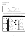
h.
Q000134E
Idle Speed Control System (ISC)
Controls the idle speed by regulating the injection quantity in order to match the target speed, which has been calculated
by the computer, with the actual speed. The functions of the ISC can be broadly divided into the following two items:
(1)
Auto ISC
Controls the idle speed in accordance with the water temperature.
Target Speed
Water Temperature
Q000135E
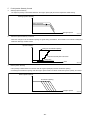
(2)
Manual ISC
Controls the idle speed in accordance with the idle speed indicated on the manual idle setting knob provided at the driver's seat.
Target Speed
ISC Knob Terminal Voltage
Q000136E
-28-
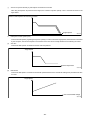
(3)
Air Conditioner Idle-up Control
When the conditions shown in the chart on the right are realized, bring the idle-up speed to constant rpm.
Conditions
Air Conditioning SW = "ON"
Clutch SW = "ON" (Clutch Connection)
Neutral SW = "ON" (Neutral)
Q000137E
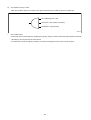
i.
Auto Cruise Control
• Controls the actual vehicle speed by regulating the injection quantity in order to match the target speed that has been
calculated by the computer with the actual speed.
• The CRS ECU controls the injection quantity in accordance with signals from the cruise control computer.
-29-
G. Fuel Injection Timing Control
The characteristics of the fuel injection timing vary depending on whether it is the main injection or the pilot injection.
Although either the NE sensor or the auxiliary NE sensor is the reference for controlling the injection timing, the NE sensor is ordinarily used for this purpose.
a.
Main Injection Timing
• The basic injection timing is calculated in accordance with the final injection quantity, the engine speed, and the water
temperature (with map correction).
• While starting, it is calculated in accordance with the water temperature and the engine speed.
Basic Injection Timing
Final Injection Quantity
Engine Speed
Q000138E
b.
Pilot Injection timing (Pilot Interval)
• The pilot injection timing is controlled by adding the pilot interval to the main injection timing.
• The pilot interval is calculated in accordance with the final injection quantity, the engine speed, and the water temperature
(with map correction).
• While starting, it is calculated in accordance with the water temperature and the engine speed.
Pilot Interval
Final Injection Quantity
Engine Speed
Q000139E
c.
Fuel Injection Pressure
• A value is calculated as determined in accordance with the final injection quantity and the engine speed.
• While starting, it is calculated in accordance with the water temperature and the engine speed.
Rail Pressure
Final Injection Quantity
Engine Speed
Q000140E
-30-
3-4. Engine ECU
A. Diagnosis Codes
a.
4HK1
DTC Code
Code Description
P0643
Analog Sensor Reference Voltage Output No.1 Too High
P0642
Analog Sensor Reference Voltage Output No.1 Too Low
P0653
Analog Sensor Reference Voltage Output No.2 Too High
P0652
Analog Sensor Reference Voltage Output No.2 Too Low
P0699
Analog Sensor Reference Voltage Output No.3 Too High
P0698
Analog Sensor Reference Voltage Output No.3 Too Low
P0118
Coolant Temp. Sensor Signal Too High
P0117
Coolant Temp. Sensor Signal Too Low
P0113
Intake Air Temp. Sensor Signal Too High
P0112
Intake Air Temp. Sensor Signal Too Low
P0183
Fuel Leak Temp. Sensor Signal Too High
P0182
Fuel Leak Temp. Sensor Signal Too Low
P0113
ATM Temp. Sensor Signal Too High
P0112
ATM Temp. Sensor Signal Too Low
P0193
C/Rail Press. Sensor Signal Too High
P0192
C/Rail Press. Sensor Signal Too Low
P2229
Atom Press. Sensor Signal Too High
P2228
Atom Press. Sensor Signal Too Low
P0238
Boost Pressure Sensor Signal Too High
P0237
Boost Pressure Sensor Signal Too Low
P0563
Ignition1 Voltage Too High
P0562
Ignition1 Voltage Too Low
P0103
MAF Sensor Signal Too High
P0102
MAF Sensor Signal Too Low
P1597
PTO Accelerator Sensor Signal Too High
P1594
Idleup Signal Too High
P1593
Idleup Signal Too Low
P0406
EGR Position Signal Too High
P0405
EGR Position Signal Too Low
P0571
Cruise / Brake Switch Circuit Malfunction
P0567
Cruise Resume / Accelerator Signal
P0568
Cruise Set / Coast Signal Malfunction
P0335
Crank Sensor No Pulse
P0340
Cam Sensor No Pulse
P0092
SCV (+) output short to BATT
SCV (-) output short to BATT
-31-
DTC Code
P0091
Code Description
SCV (+) output open Load / short to GND
SCV (-) output open Load / short to GND
SCV coil open
P1264
COM1 output short to BATT;
TWV1 or 3 (or 5) output short to BATT
P1263
COM1 output short to GND;
TWV1 or 3 (or 5) output short to GND
P2152
COM1 output open load;
Both TWV1 or 3 (or 5) output open load
P1266
COM2 output short to BATT;
TWV2 or 4 (or 6) output short to BATT
P1265
COM2 output short to GND;
TWV2 or 4 (or 6) output short to GND
P2155
COM2 output open load;
Both TWV2 or 4 (or 6) output open load
P0201
TWV1 output open load
Injector#1 coil open
P0202
TWV2 output open load
Injector#3 coil open
P0203
TWV3 output open load
Injector#4 coil open
P0204
TWV4 output open load
Injector#2 coil open
P1261
Capacitor charge-up circuit malfunction (insufficient charge)
P1261
Capacitor charge-up circuit malfunction (excessive charge)
P0088
Common rail pressure exceeds upper
P0088
Common rail pressure exceeds hi upper limit
P0382
Glow Controller Command Line Short to BATT
P0382
Glow Controller Command Line Open Load / Short to GND
P1094
C/Rail Press. Sensor Performance Invalid included fuel leak
P0087
P/L (pressure limiter) activated
P1404
EGR Position Error
P0400
EGR Duty Error
P0500
Vehicle Speed Sensor Malfunction
P0606
CPU fault;
-Main CPU fault
P0606
CPU fault;
-Watchdog IC fault
P0602
EEPROM/EERPOM Emulation via Flash EPROM Write Error
P0219
Engine overrun
P0512
Starter Switch Short to BATT
-32-
DTC Code
P0686
Code Description
Main relay diagnostics;
Main relay stuck closed
P0089
Supply pump control valve (suction control valve) stuck
P0299
Boost Pressure Sensor exceeds lower limit
P0234
Boost Pressure Sensor exceeds upper limit
P2293
Supply pump protection
P2294
Supply pump exchange
P1093
Supply pump malfunction
P2122
Accelerator Pedal Position Sensor 1 Low Voltage
P2123
Accelerator Pedal Position Sensor 1 High Voltage
P2127
Accelerator Pedal Position Sensor 2 Low Voltage
P2128
Accelerator Pedal Position Sensor 2 High Voltage
P2132
Accelerator Pedal Position Sensor 3 Low Voltage
P2133
Accelerator Pedal Position Sensor 3 High Voltage
P1125
Pedal Position Sensor Circuit Intermittent
P2138
Accelerator Pedal Position Sensor 1, 2 Correlation Error
P2140
Accelerator Pedal Position Sensor 2, 3 Correlation Error
P2139
Accelerator Pedal Position Sensor 1, 3 Correlation Error
U2104
CAN Bus Error
U2106
CAN TCM SOH Diagnostic
P0602
QR Code Not Programmed
P0602
QR Code ERROR
-33-
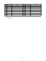
b.
6HK1
DTC Code
Code Description
P0641
Analog Sensor Reference Voltage Output No.1 Too High
P0641
Analog Sensor Reference Voltage Output No.1 Too Low
P0651
Analog Sensor Reference Voltage Output No.2 Too High
P0651
Analog Sensor Reference Voltage Output No.2 Too Low
P1646
Analog Sensor Reference Voltage Output No.3 Too High
P1646
Analog Sensor Reference Voltage Output No.3 Too Low
P0118
Coolant Temp. Sensor Signal Too High
P0117
Coolant Temp. Sensor Signal Too Low
P0113
Intake Air Temp. Sensor Signal Too High
P0112
Intake Air Temp. Sensor Signal Too Low
P0183
Fuel Leak Temp. Sensor Signal Too High
P0182
Fuel Leak Temp. Sensor Signal Too Low
P0523
Oil Press. Sensor Signal Too High
P0522
Oil Press. Sensor Signal Too Low
P0463
Fuel Level Sensor1 Signal Too High
P0462
Fuel Level Sensor1 Signal Too Low
P1433
Fuel Level Sensor2 Signal Too High
P1432
Fuel Level Sensor2 Signal Too Low
P0193
C/Rail Press. Sensor Signal Too High
P0192
C/Rail Press. Sensor Signal Too Low
P0190
C/Rail Press. Sensor Signal keeping the middle range
P0108
Atom Press. Sensor Signal Too High
P0107
Atom Press. Sensor Signal Too Low
P0238
Boost Pressure Sensor Signal Too High
P0237
Boost Pressure Sensor Signal Too Low
P0563
Ignition1 Voltage Too High
P0562
Ignition1 Voltage Too Low
P2003
MAF Sensor Signal Too High
P2004
MAF Sensor Signal Too Low
P2005
PTO Accelerator Sensor Signal Too High
P2007
VNT Current Too High
P2008
VNT Current Too Low
P0704
Clutch Pedal Switch Circuit
P0571
Cruise / Brake Switch Circuit Malfunction
P0571
Cruise / Brake Switch Circuit Malfunction
P0567
Cruise Resume / Accelerator Signal
P0568
Cruise Set / Coast Signal Malfunction
P0335
Crank Sensor No Pulse
P0385
Cam Sensor No Pulse
-34-
DTC Code
P0092
Code Description
SCV (+) output short to BATT
SCV (-) output short to BATT
P0091
SCV (+) output open Load / short to GND
SCV (-) output open Load / short to GND
SCV coil open
P1264
COM1 output short to BATT;
TWV1 or 3 (or 5) output short to BATT
P1263
COM1 output short to GND;
TWV1 or 3 (or 5) output short to GND
P2011
COM1 output open load;
Both TWV1 or 3 (or 5) output open load
P1266
COM2 output short to BATT;
TWV2 or 4 (or 6) output short to BATT
P1265
COM2 output short to GND;
TWV2 or 4 (or 6) output short to GND
P2012
COM2 output open load;
Both TWV2 or 4 (or 6) output open load
P0201
TWV1 output open load
Injector#1 coil open
P0202
TWV2 output open load
Injector#5 coil open
P0203
TWV3 output open load
Injector#3 coil open
P0204
TWV4 output open load
Injector#6 coil open
P0205
TWV5 output open load
Injector#2 coil open
P0206
TWV6 output open load
Injector#4 coil open
P1261
Capacitor charge-up circuit malfunction (insufficient charge)
P1261
Capacitor charge-up circuit malfunction (excessive charge)
P1088
Common rail pressure exceeds hi upper limit
P0382
Glow Controller Command Line Short to BATT
P0382
Glow Controller Command Line Open Load / Short to GND
P0500
Vehicle Speed Sensor Malfunction
P0087
C/Rail Press. Sensor Performance Invalid included fuel leak
P1087
P/L (pressure limiter) activated
P2565
VNT Position Signal Too high
P2564
VNT Position Signal Too low
P2900
VNT Position Stick
P2901
EGR Brushless motor Position Sensor Signal Invalid
P2902
EGR Brushless motor Performance Error
-35-
DTC Code
Code Description
P2903
EGR Valve open/Close Stick
P0606
CPU fault;
-Main CPU fault
P0606
CPU fault;
-Watchdog IC fault
P1621
EEPROM/EERPOM Emulation via Flash EPROM Write Error
P0219
Engine overrun
P0512
Starter Switch Short to BATT
P2920
Main relay diagnostics;
Main relay stuck closed
P0088
Supply pump control valve (suction control valve) stuck
P0234
Boost Pressure Sensor exceeds upper limit
P0234
Boost Pressure Sensor exceeds upper limit (Long time)
P2921
Supply pump protection
P2922
Supply pump exchange
P2923
Supply pump malfunction
P1277
Accelerator Pedal Position Sensor 1 Low Voltage
P1278
Accelerator Pedal Position Sensor 1 High Voltage
P1282
Accelerator Pedal Position Sensor 2 Low Voltage
P1283
Accelerator Pedal Position Sensor 2 High Voltage
P1287
Accelerator Pedal Position Sensor 3 Low Voltage
P1288
Accelerator Pedal Position Sensor 3 High Voltage
P1125
Pedal Position Sensor Circuit Intermittent
P1271
Accelerator Pedal Position Sensor 1, 2 Correlation Error
P1272
Accelerator Pedal Position Sensor 2, 3 Correlation Error
P1273
Accelerator Pedal Position Sensor 1, 3 Correlation Error
U1300
Class2 Bus Short to Ground
U1301
Class2 Bus Short to Battery
U2104
CAN Bus Error
P0461
Fuel Level Sensor Circuit Performance
P0602
QR Code Not Programmed
P0602
QR Code ERROR
-36-
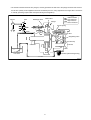
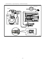
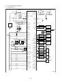
B. ECU External Wiring Diagram
a.
4HK1 Diagram (1)
STARTER RELAY
START
KEY SW
A
ON
STA-SW
IG1-SW
ACC
LOCK
A
STAEN-REL
MAIN-RELAY
C
STARTER CUT RELAY
M-REL
ECU
M-REL
+B
SCVHI
+B
B
+B
SCVHI
SCV
C
A
SCVLO
GL-CONT
+
SCVLO
GLOW-RELAY
BATTERY
-
(GM1-FB)
CRANK
POSITION
SENSOR
NE+
(GM2-FB)
NE-
(GM3-FB)
NE-SLD
(GM4-FB)
SPEED
SENSOR
SPD
AT
BATT
A
METER
BK1-SW
A
G-VB
BK2-SW
G
CRM-SW
G-SLD
PB-VCC
CRR-SW
PBOOST
PB-GND
CRS-SW
TAP DOWN
CAM ANGLE
SENSOR
(HALL)
BOOST
PRESSURE
SENSOR
TAP UP
PFUEL-VCC
PFUEL
PFUEL
RAIL
PRESSURE
SENSOR
PFUEL-GND
PTOEN-SW
APS1-VCC
PTO SW
PTOEN-REL
APS1
APS1
APS1-GND
PTOFB-SW
PTO ENABLE RELAY
APS2-VCC
OPTION
APS2
APS2
APS2-GND
PTODIS-SW
APS3-VCC
SHUTDOWN-SW
APS3
APS3
APS3-GND
RSET-SW
IDLUP-VCC
RRES-SW
IDLUP
IDLUP-GND
IDLE UP
VOLUME
SSPA-SW
SSPB-SW
CCDIS-SW
PACL-VCC
PACL
PACL-GND
PTO ACCEL
SENSOR
(TQLIM-SW)
(SP2)
IGBC-SW
(SP2-GND)
CL-SW
(TQCUT-SW)
FUEL-SW *1
(SP1-VCC)
(SP1)
(SP1-GND)
Q000538E
-37-
4HK1 Diagram (2)
DIAG CLEAR-SW (LOL-SW)
(POIL-VCC)
REF-SW
(POIL)
POIL-GND
AC-SW
ECU
(FQ1)
THF1
FUEL TEMP
(THF2)
INTAKE AIR TEMP
B
(INCA-BAT)
MAF
(INCA-GND)
MAF
MAF-GND
THWOUT
(SP3-GND)
TACHO
(SP3)
(ATMT-GND)
TWISTED PAIR
CAN1H
(ATMT)
CAN1L
AT
CONTROLLER
COOLANT TEMP
THA
(FQ3)
METER
THW
(THO)
(FQ2)
(ACGL-SW)
(CAN1-SLD)
(ACG-F)
AT-TACHO
COMMON1
COMMON1
CYL1
CRSET-L
TWV-A
CYL4
MIL
TWV-C
CRM-L
COMMON2
COMMON2
CYL3
TWV-B
GL-L
ATM
PRESSURE
b.
METER
ABS
(EXB-L)
AT
CLASS2
TOOL
CLASS2
TOOL
KWP2000
CYL2
TWV-D
A
EXB-SW
EXHAUST
BRAKE
RELAY
EXHAUST BRAKE
CUT RELAY
C
AT
M+
EXB-REL
EBM1
EGR DC
BRUSH MOTOR
EBM2
M-
ABS
EXHAUST BRAKE
RELAY (CHARGE)
EGR-VCC
EGR POSITION
SENSOR
EGP-POS
EGR-GND
P-GND
(EBM-W)
(EGR-UPOS)
(EGR-VPOS)
(EGR-WPOS)
P-GND
P-GND
P-GND
(IDM1)
(IDM2)
GND
GND
INT-VCC
CASE-GND
INT
INT-GND
Q000539E
-38-
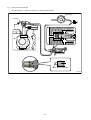
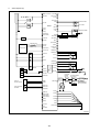
c.
6HK1 Diagram (1)
STARTER
SW
STA-SW
BATT
SCVHI
IG0-SW
SCVHI
IG1-SW
IGN A
ECU
IGN B
SCV
SCVLO
SCVLO
A
B
NE+
CRANK
POSITION
SENSOR
NE-
GLOW RELAY
NE-SLD
GL-REL
LCT TCM
TWISTED PAIR
VSS+
VSSGLOW
PLUG
C
ENGINE
BLOCK
POWER
MAINTAIN
RELAY
VSS-SLD
(+B) *1
+B
G-VB
+B
G
M-REL
G-SLD
M-REL
PBOOST
PB-VCC
GL-L
PB-GND
PFUEL
PFUEL
FIDL-L
IGNITION3
BK1-SW
PFUEL-VCC
BK2-SW
PFUEL-GND
CRM-SW
CAM ANGLE
SENSOR
(HALL)
BOOST
SENSOR
PRESSURE
PRESSURE
SENSOR
COMMON RAIL
APS1-VCC
APS1
CRR-SW
APS1
APS1-GND
CRS-SW
TOP DOWN
VEHICLE
SPEED
SENSOR
APS2-VCC
TOP UP
APS2
APS2
APS2-GND
APS3-VCC
PTO SW
(UPFTR SUP)
(UPFTR SUP)
PTOEN-SW
PTOEN-REL
APS3
APS3
APS3-GND
PACL-VCC
B
PTOFB-SW
PTO ENABLE RELAY
PACL
PACL-GND
POIL-VCC
PTODIS-SW
RSET-SW
RRES-SW
RRPA-SW
RRPB-SW
CCDIS-SW
POIL
POIL-GND
PTO ACCEL
SENSOR
ENGINE OIL
PRESSURE
SENSOR
THW
COOLANT TEMP
THF1
FUEL TEMP#1
*2 THF2
FUEL TEMP#2
THD
THA
ENGINE OIL TEMP
INTAKE AIR TEMP
IGBC-SW
CL-SW
FAXLE-SW
C
MAF
MAF
MAF-GND
A
*1: In case of connecting to outside wiring, note that this termonal is connected to +B inside ECU.
*2: This terminal is unused.
-39-
Q000540E
d.
6HK1 Diagram (2)
REV-SW
A/C REQUEST SW AC HI-PRESS SW
LOL-SW
FIDL-SW
AC-SW
COM-GND
LFUEL1
4WD-SW
LCL-SW
ACGL-SW
ACG
ACG-F
ACG
LFUEL2
WIF-SW
AIR 2SPD. AXLE SENSOR
FUEL LEVEL#1
N-SW
FUEL LEVEL#2
IGN (CRANK)
STARTER R/L
VB
STAEN-REL
CLUTCH SW
ELECTRIC 2SPD. AXLE
SW AUTOMATC
ECU
COMMON1
COMMON1
2SAXLE-SW
CYL1
TWV-A
IGN3
MANUAL
IGN3
CYL2
TWV-E
2SPD.
AXLE
MOTER
CYL3
TWV-C
COMMON2
COMMON2
ATM
PRESSURE
CYL4
TWV-F
CYL5
TWV-B
A/C RELAY LOW PRESSURE SW
CYL6
BATT
TWV-D
A/C CLUTCH
ACCL-REL
CLUSTER
EXB-SW
MIL
TACHO
VSOUT1
EXHT Telltail-TTM
B
EXHT BRK SOLENOID
TWISTED PAIR
CAN1H
TCM
EXB-REL
ABS
CAN1L
CAN1-SLD
CHASSIS
BUILDER
TECH II
W/ABS
NO ABS
P-GND
VSOUT2
P-GND
CLASS2
CLASS2
TCM
LCT
WTERC
P-GND
P-GND
GND
GND
DIAGCL-SW
CASE-GND
EGR-VCC
EGR-UPOS
EBM-U
EGR-VPOS
EGR VALVE
DRIVE DC BRUSH-LESS
MOTOER
EBM-V
EGR-WPOS
EBM-W
EGR-GND
C
AVNT
NOTE:
Un lock
Run
Crank
Lock/Accessory
IGN0 IGN1 CRANK IGN3
1
0
0
0
1
1
0
1
1
1
1
0
0
0
0
0
AVNT
VNTPOS-VCC
VNTPOS-SIG
AVNT POSITION
SENSOR
VNTPOS-GND
Q000541E
-40-
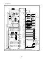
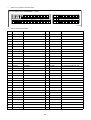
C. ECU Connector Diagram
a.
4HK1 ECU Connector Terminal Layout
ECU CONNECTOR PIN ASSIGNMENT : 154PIN
㪘㪄㪎㪊
㪘㪄㪎㪏
㪂㪙
㪞㪣㩷
㪄㪚㪦㪥㪫
㪧㪫㪦㪜㪥㩷 㪪㪫㪘㪜㪥㩷
㪄㪩㪜㪣
㪄㪩㪜㪣
㪂㪙
㪂㪙
㪙㪘㪫㪫
㪤㪄㪩㪜㪣
㪜㪯㪙㩷
㪄㪩㪜㪣
㪤㪄㪩㪜㪣
㪘㪄㪋㪐
㪘㪄㪉㪌
㪚㪘㪪㪜㩷
㪄㪞㪥㪛
㪘㪄㪈
㪧㪄㪞㪥㪛
㪧㪄㪞㪥㪛 㪫㪘㪚㪟㪦
㪧㪄㪞㪥㪛
㪧㪄㪞㪥㪛
㪞㪥㪛
㪘㪫㪄㩷
㪚㪩㪪㪜㪫㩷
㪤㪠㪣 㪚㪩㪤㩷
㪄㪣
㪫㪘㪚㪟㪦
㪄㪣
㪘㪧㪪㪈㩷 㪘㪧㪪㪉㩷 㪘㪧㪪㪊㩷
㪧㪘㪚㪣㩷 㪠㪛㪣㪬㪧
㪄㪭㪚㪚 㪄㪭㪚㪚 㪄㪭㪚㪚
㪄㪭㪚㪚 㪄㪭㪚㪚
㪘㪄㪌㪋
㪘㪄㪊㪇
㪠㪞㪙㪚㩷
㪄㪪㪮
㪙㪢㪈㩷
㪄㪪㪮
㪞㪣㪄㪣
㪚㪚㪛㪠㪪㩷
㪄㪪㪮
㪙㪢㪉㩷 㪚㪣㩷
㪄㪪㪮 㪄㪪㪮
㪪㪪㪧㪙
㪄㪪㪮
㪛㪠㪘㪞㩷
㪚㪣㪜㪘㪩㩷
㪄㪪㪮
㪩㪪㪜㪫㩷 㪩㪩㪜㪪㩷 㪧㪫㪦㪜㪥 㪧㪫㪦㪛㪠㪪㩷 㪧㪫㪦㪝㪙㩷
㪄㪪㪮 㪄㪪㪮 㪄㪪㪮 㪄㪪㪮 㪄㪪㪮
㪜㪯㪙㩷
㪩㪜㪝
㪄㪪㪮
㪄㪪㪮
㪪㪧㪛
㪘㪧㪪㪈 㪘㪧㪪㪉 㪘㪧㪪㪊 㪧㪘㪚㪣 㪠㪛㪣㪬㪧
㪚㪘㪥㪈㩷 㪚㪘㪥㩷
㪄㪪㪣㪛 㪈㪥
㪘㪧㪪㪈㩷 㪘㪧㪪㪉㩷 㪘㪧㪪㪊㩷 㪧㪘㪚㪣㩷 㪠㪛㪣㪬㪧
㪄㪞㪥㪛 㪄㪞㪥㪛 㪄㪞㪥㪛 㪄㪞㪥㪛 㪄㪞㪥㪛
㪞㪥㪛
㪪㪪㪧㪘
㪄㪪㪮
㪪㪟㪬㪫㩷
㪛㪦㪮㪥㩷
㪄㪪㪮
㪚㪘㪥㩷 㪢㪮㪧㩷
㪈㪣 㪉㪇㪇㪇
㪚㪣㪘㩷
㪪㪪㪉
㪘㪚㩷 㪚㪩㪤㩷 㪚㪩㪩㩷
㪄㪪㪮 㪄㪪㪮 㪄㪪㪮
㪚㪣㪘㩷
㪠㪞㪠㪄㪪㪮
㪪㪪㪉
㪘㪄㪍
㪘㪄㪐㪍
㪪㪫㪘㩷
㪄㪪㪮
㪘㪄㪎㪉
㪘㪄㪋㪏
㪚㪩㪪㩷
㪄㪪㪮
㪫㪟㪮㩷
㪦㪬㪫
㪙㪄㪌
㪙㪄㪍
㪙㪄㪋㪍
㪚㪦㪤㪤㪦㪥㪈
㪚㪦㪤㪤㪦㪥㪉
㪧㪙㩷
㪄㪭㪚㪚
㪧㪝㪬㪜㪣㩷 㪧㪦㪠㩷㪣㩷 㪜㪞㪩㩷 㪠㩷㪥㪫㩷 㪞㩷
㪄㪭㪚㪚 㪄㪭㪚㪚 㪄㪭㪚㪚 㪄㪭㪚㪚 㪄㪭㪙
㪪㪚㪭㪟㪠 㪫㪟㪮
㪙㪄㪊
㪙㪄㪋
㪪㪚㪭㪟㪠
㪚㪦㪤㪤㪦㪥㪈
㪚㪦㪤㪤㪦㪥㪉
㪙㪄㪊㪊
㪙㪄㪉㪇
㪙㪄㪈
㪙㪄㪉
㪙㪄㪌㪏
㪜㪞㪩㩷
㪄㪧㪦㪪
㪫㪟㪘
㪫㪟㪝㪈
㪫㪮㪭㪄㪦
㪫㪮㪭㪄㪘
㪫㪮㪭㪄㪛
㪫㪮㪭㪄㪙
㪙㪄㪋㪌
㪙㪄㪊㪉
㪪㪚㪭㪣㪦
㪪㪚㪭㪣㪦
㪜㪙㪤㪈
㪜㪙㪤㪉
㪧㪙㪦㪦㪪㪫 㪧㪝㪬㪜㪣 㪧㪝㪬㪜㪣
㪤㪘㪝
㪠㩷㪥㪫
㪞
㪥㪜㪂
㪙㪄㪎
㪘㪄㪉㪋
㪥㪜㪄
㪧㪙㩷
㪧㪝㪬㪜㪣㩷 㪧㪦㪠㩷㪣㩷 㪤㪘㪝㩷 㪠㩷㪥㪫㩷 㪜㪞㪩㩷 㪞㩷
㪥㪜㩷
㪄㪞㪥㪛 㪄㪞㪥㪛 㪄㪞㪥㪛 㪄㪞㪥㪛 㪄㪞㪥㪛 㪄㪞㪥㪛 㪄㪪㪣㪛 㪄㪪㪣㪛
㪙㪄㪈㪐㩷
Q000542E
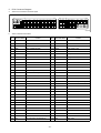
b.
4HK1 Terminal Connections
No.
Terminal Name
Content
No.
A-1
CASE-GND
CASE GND
A-31 APS1
ACCEL POSITION 1 SIG
A-2
P-GND
POWER GND
A-32 APS2
ACCEL POSITION 2 SIG
A-3
P-GND
POWER GND
A-33 APS3
ACCEL POSITION 3 SIG
A-4
GND
ECU SENSOR GND
A-34 PACL
PTO ACCEL SIG
A-5
GND
ECU SENSOR GND
A-35 IDLUP
IDLE UP SIG
A-6
N/A
(Q CONTROL RESISTOR 3)
A-36 N/A
(SP1)
A-7
APS1-GND
V5RTN1
A-37 N/A
(SP2)
A-8
APS2-GND
V5RTN2
A-38 N/A
(ATM TEMP SIG)
A-9
APS3-GND
V5RTN3
A-39 SPD
SPEED INPUT
A-10 PACL-GND
PTO ACCEL GND
A-40 —
—
A-11 IDLUP-GND
IDLE UP GND
A-41 N/A
(ACG-F PULSE INPUT)
A-12 N/A
(SP3 GND)
A-42 —
—
A-13 N/A
(ATM TEMP GND)
A-43 N/A
(GLOW MONITOR2 FEEDBACK)
A-14 —
—
A-44 N/A
(GLOW MONITOR3 FEEDBACK)
A-15 N/A
(SP1-GND)
A-45 AC-SW
A/C CLUTCH REQUEST SW
A-16 CAN1-SLD
CAN1 SHIELD GND
A-46 CRM-SW
RUISE ENABLE (ON/OFF) SW
A-17 CAN1H
CAN1 HIGH
A-47 CRR-SW
CRUISE RESUME/ACCEL SW
A-18 CAN1L
CAN1 LOW
A-48 CRS-SW
CRUISE SET/COAST SW
A-19 KWP2000
ISO14230
A-49 +B
POWER
A-20 CLASS2
J1850
A-50 +B
POWER
A-21 CLASS2
J1850
A-51 BATT
BATTERY
A-22 —
—
A-52 M-REL
POWER MAINTAIN RELAY
A-23 IG1-SW
IGNITION 1
A-53 M-REL
POWER MAINTAIN RELAY
A-24 THWOUT
THW PWM OUTPUT
A-54 APS1-VCC
VBREF1
A-25 —
—
A-55 APS2-VCC
VBREF2
A-26 P-GND
POWER GND
A-56 APS3-VCC
VBREF3
A-27 P-GND
POWER GND
A-57 —
—
A-28 TACHO
TACHO
A-58 PACL-VCC
PTO ACCEL VCC
A-29 N/A
(Q CONTROL RESISTOR 1)
A-59 IDLUP-VCC
IDLE UP VCC
A-30 N/A
(Q CONTROL RESISTOR 2)
A-60 N/A
(SP1 VCC)
-41-
Terminal Name
Content
No.
Terminal Name
Content
No.
Terminal Name
Content
A-61 N/A
(ACG-L INPUT)
A-79 GL-L
GLOW LAMP
A-62 BK1-SW
BRAKE 1 SW
A-80 MIL
CHECK ENGINE LAMP
A-63 BK2-SW
BRAKE 2 SW
A-81 CRM-L
CRUISE MAIN LAMP
A-64 CL-SW
CLUTCH SW
A-82 AT-TACHO
AT-TACHO
A-65 SHUTDOWN-SW ENGINE SHUTDOWN SW
A-83 N/A
(SP2 GND)
A-66 DIAG CLEAR-SW DIAG CLEAR SW
A-84 CRSET-L
CRUISE SET LAMP
A-67 EXB-SW
EXHAUST BRAKE SW
A-85 N/A
(SP2)
A-68 —
—
A-86 IGBC-SW
IGNORE BRAKE/CLUTCH SW
A-69 REF-SW
REFRIGERATOR SW
A-87 N/A
(TORQUE LIMIT SW)
A-70 N/A
(GLOW MONITOR1 FEEDBACK)
A-88 CCDIS-SW
CAB CONTROL DISABLE SW
A-71 N/A
(TORQUE CUT SW)
A-89 SSPA-SW
SET SPEED A SW
A-72 N/A
(GLOW MONITOR4 FEEDBACK)
A-90 SSPB-SW
SET SPEED B SW
A-73 +B
POWER
A-91 RSET-SW
REMOTE SET SW
A-74 GL-CONT
GLOW CONTOROLLER
A-92 RRES-SW
REMOTE RESUME SW
A-75 PTOEN-REL
PTO ENGAGE RELAY
A-93 PTOEN-SW
PTO ENGAGE SW
A-76 STAEN-REL
STARTER ENABLE RELAY
A-94 PTODIS-SW
PTO DISABLE SW
A-77 EXB-REL
EXHAUST BRAKE RELAY
A-95 PTOFB-SW
PTO FEEDBACK SW
A-78 N/A
(EXHAUST BRAKE LAMP)
A-96 STA-SW
CRANKING REQUEST SW
No.
Terminal Name
Content
No.
B-1
N/A
(INTAKE DC MOTOR1)
B-22 —
—
B-2
N/A
(INTAKE DC MOTOR2)
B-23 N/A
(INCA-BAT)
B-3
COMMON1
INJECTOR POWER1
B-24 PBOOST
BOOST PRESSURE SIG.
B-4
COMMON2
INJECTOR POWER2
B-25 PFUEL
RAIL PRESSURE SIG.
B-5
COMMON1
INJECTOR POWER1
B-26 PFUEL
RAIL PRESSURE SIG.
B-6
COMMON2
INJECTOR POWER2
B-27 N/A
(OIL PRESSURE SIG.)
B-7
EBM1
EGR DC MOTOR 1
B-28 MAF
MAF SIGNAL
B-8
EBM2
EGR DC MOTOR 2
B-29 INT
INTAKE POSITION SIG.
B-9
N/A
(EGR BRUSHLESS MOTOR W)
B-30 G
CAM ANGLE
B-10 —
—
B-31 NE+
CRANK POSITION+
B-11 N/A
(INCA-GND)
B-32 NE-
CRANK POSITION-
B-12 PB-GND
BOOST PRESSURE GND
B-33 SCVHI
SCV HIGH SIDE
B-13 PFUEL-GND
RAIL PRESSURE GND
B-34 SCVHI
SCV HIGH SIDE
B-14 POIL-GND
OIL PRESSURE GND
B-35 THW
COOLANT TEMP.
B-15 MAF-GND
MAF GND
B-36 N/A
(ENGINE OIL TEMP.)
B-16 INT-GND
INTAKE POSITION GND
B-37 THA
INTAKE AIR TEMP.
B-17 EGR-GND
EGR POSITION GND
B-38 N/A
(EGR-U POSITION SIG.)
B-18 G-SLD
CAM ANGLE GND
B-39 N/A
(EGR-V POSITION SIG.)
B-19 NE-SLD
CRANK POSITION GND
B-40 N/A
(EGR-W POSITION SIG.)
B-20 SCVLO
SCV LOW SIDE
B-41 THF1
FUEL TEMP
B-21 SCVLO
SCV LOW SIDE
B-42 N/A
(FUEL TEMP. #2)
-42-
Terminal Name
Content
No.
Terminal Name
Content
No.
Terminal Name
Content
B-43 TWV-D
INJECTOR D(CYL2)
B-51 G-VB
CAM ANGLE VB
B-44 —
—
B-52 N/A
(LOW OIL LEVEL SW)
B-45 TWV-B
INJECTOR B(CYL3)
B-53 EGR-POS
EGR-POSITION SIG. (DC MOTOR)
B-46 PB-VCC
BOOST PRESSURE VCC
B-54 —
—
B-47 PFUEL-VCC
RAIL PRESSURE VCC
B-55 —
—
B-48 POIL-VCC
OIL PRESSURE VCC
B-56 TWV-C
INJECTOR C(CYL4)
B-49 EGR-VCC
EGR POSITION VCC
B-57 —
—
B-50 INT-VCC
INTAKE POSITION VCC
B-58 TWV-A
INJECTOR A(CYL1)
< NOTE >
• N/A: Component is not mounted (circuit pattern only). Note that the VCC and GND and pin No. A-78 for sensors are
connected inside ECU.
-43-
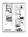
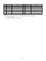
c.
6HK1 ECU Connector Terminal Layout
ECU CONNECTOR PIN ASSIGNMENT : 154PIN
㪘㪄㪎㪊
㩿㪂㪙㪀 㪞㪣㩷
㪄㪩㪜㪣
㪂㪙
㪂㪙
㪧㪫㪦㪜㪥㩷 㪪㪫㪘㪜㪥㩷
㪄㪩㪜㪣
㪄㪩㪜㪣
㪜㪯㪙㩷
㪄㪩㪜㪣
㪙㪘㪫㪫
㪤㪄㪩㪜㪣
㪤㪄㪩㪜㪣
㪘㪄㪋㪐
㪘㪄㪉㪌
㪚㪘㪪㪜㩷
㪄㪞㪥㪛
㪘㪄㪈
㪧㪄㪞㪥㪛
㪧㪄㪞㪥㪛 㪫㪘㪚㪟㪦
㪧㪄㪞㪥㪛
㪧㪄㪞㪥㪛
㪞㪥㪛
㪘㪄㪎㪏
㪝㩷㪠㩷㪛㪣㩷
㪞㪣㪄㪣
㪄㪣
㪭㪪㩷 㪭㪪㩷
㪤㩷㪠㩷㪣 㪦㪬㪫㪈 㪦㪬㪫㪉
㪘㪧㪪㪈㩷 㪘㪧㪪㪉㩷 㪘㪧㪪㪊㩷
㪄㪭㪚㪚 㪄㪭㪚㪚 㪄㪭㪚㪚
㪘㪄㪌㪋
㪘㪄㪊㪇
㪚㪩㪪㪜㪫㩷
㪄㪣
㪙㪢㪈㩷
㪄㪪㪮
㪧㪘㪚㪣㩷
㪄㪭㪚㪚
㪚㪚㪛㪠㪪㩷 㪪㪪㪧㪘 㪪㪪㪧㪙
㪄㪪㪮 㪄㪪㪮 㪄㪪㪮
㪛㪠㪘㪞㩷
㪙㪢㪉㩷 㪚㪣㩷 㪪㪟㪬㪫㩷
㪛㪦㪮㪥㩷 㪚㪣㪜㪘㪩㩷
㪄㪪㪮 㪄㪪㪮 㪄㪪㪮 㪄㪪㪮
㪣㪝㪬㪜㪣㪈 㪣㪝㪬㪜㪣㪉 㪭㪪㪪㪂 㪭㪪㪪㪄 㪘㪚㪞㪄㪝
㪘㪧㪪㪈 㪘㪧㪪㪉 㪘㪧㪪㪊 㪧㪘㪚㪣
㪘㪧㪪㪈㩷 㪘㪧㪪㪉㩷 㪘㪧㪪㪊㩷 㪧㪘㪚㪣㩷
㪄㪞㪥㪛 㪄㪞㪥㪛 㪄㪞㪥㪛 㪄㪞㪥㪛
㪞㪥㪛
㪠㪞㪙㪚㩷
㪄㪪㪮
㪚㪦㪤㩷
㪄㪞㪥㪛
㪭㪪㪪㩷
㪄㪪㪣㪛
㪩㪪㪜㪫㩷 㪩㪩㪜㪪㩷 㪧㪫㪦㪜㪥 㪧㪫㪦㪛㪠㪪㩷 㪧㪫㪦㪝㪙㩷
㪄㪪㪮 㪄㪪㪮 㪄㪪㪮 㪄㪪㪮 㪄㪪㪮
㪜㪯㪙㩷 㪝㪬㪜㪣
㪄㪪㪮 㪄㪪㪮
㪩㪜㪝
㪄㪪㪮
㪉㪪㪘㪯㪣㪜㩷 㪋㪮㪛㩷 㪘㪚㩷
㪄㪪㪮
㪄㪪㪮 㪄㪪㪮
㪚㪘㪥㪈㩷 㪚㪘㪥㪈㪟 㪚㪘㪥㪈㪣
㪄㪪㪣㪛
㪚㪣㪘㩷
㪪㪪㪉
㪣㪚㪣㩷 㪩㪜㪭㩷
㪄㪪㪮 㪄㪪㪮
㪚㪩㪤㩷 㪚㪩㪩㩷
㪄㪪㪮 㪄㪪㪮
㪘㪄㪐㪍
㪪㪫㪘㩷
㪄㪪㪮
㪮㩷㪠㩷㪝㩷
㪄㪪㪮
㪘㪄㪎㪉
㪘㪄㪋㪏
㪚㪩㪪㩷
㪄㪪㪮
㪚㪣㪘㩷 㪠㪞㪦㪄㪪㪮 㪠㪞㪠㪄㪪㪮
㪪㪪㪉
㪙㪄㪌
㪙㪄㪍
㪙㪄㪋㪍
㪚㪦㪤㪤㪦㪥㪈
㪚㪦㪤㪤㪦㪥㪉
㪧㪙㩷
㪄㪭㪚㪚
㪧㪝㪬㪜㪣㩷 㪧㪦㩷㪠㩷㪣㩷 㪜㪞㪩㩷 㪠㩷㪥㪫㩷 㪞㩷
㪄㪭㪚㪚 㪄㪭㪚㪚 㪄㪭㪚㪚 㪄㪭㪚㪚 㪄㪭㪙
㪪㪚㪭㪟㪠 㪫㪟㪮
㪙㪄㪊
㪙㪄㪋
㪪㪚㪭㪟㪠
㪚㪦㪤㪤㪦㪥㪈
㪚㪦㪤㪤㪦㪥㪉
㪙㪄㪊㪊
㪙㪄㪉㪇
㪙㪄㪈
㪙㪄㪉
㪪㪚㪭㪣㪦
㪪㪚㪭㪣㪦
㪜㪙㪤㩷
㪄㪬
㪙㪄㪎
㪜㪙㪤㩷 㪜㪙㪤㩷
㪄㪭
㪄㪮
㪘㪭㪥㪫
㪘㪄㪉㪋
㪘㪄㪍
㪙㪄㪌㪏
㪫㪟㪦
㪣㪦㪣㩷
㪄㪪㪮
㪫㪮㪭㪄㪦 㪫㪮㪭㪄㪜 㪫㪮㪭㪄㪘
㪜㪞㪩㩷 㪜㪞㪩㩷
㪫㪟㪘 㪜㪞㪩㩷
㪄㪬㪧㪦㪪 㪄㪭㪧㪦㪪 㪄㪮㪧㪦㪪 㪫㪟㪝㪈 㪫㪟㪝㪉 㪫㪮㪭㪄㪛 㪫㪮㪭㪄㪝 㪫㪮㪭㪄㪙
㪙㪄㪋㪌
㪙㪄㪊㪉
㪞 㪥㪜㪂 㪥㪜㪄
㪧㪙㪦㪦㪪㪫 㪧㪝㪬㪜㪣 㪧㪝㪬㪜㪣 㪧㪦㩷㪠㩷㪣㩷 㪤㪘㪝 㪭㪥㪫㪧㪦㪪㩷
㪄㪪㪠㪞
㪥㪜㩷
㪧㪙㩷
㪧㪝㪬㪜㪣㩷 㪧㪦㩷㪠㩷㪣㩷 㪤㪘㪝㩷 㪭㪥㪫㪧㪦㪪㩷 㪜㪞㪩㩷 㪞㩷
㪄㪞㪥㪛 㪄㪞㪥㪛 㪄㪞㪥㪛 㪄㪞㪥㪛 㪄㪞㪥㪛 㪄㪞㪥㪛 㪄㪪㪣㪛 㪄㪪㪣㪛
㪙㪄㪈㪐㩷
Q000543E
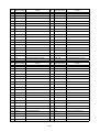
d.
No.
6HK1 Terminal Connections
Terminal Name
Content
No.
Terminal Name
Content
A-1
CASE-GND
CASE GND
A-32 APS2
ACCEL POSITION 2 SIG
A-2
P-GND
POWER GND
A-33 APS3
ACCEL POSITION 3 SIG
A-3
P-GND
POWER GND
A-34 PACL
PTO ACCEL SIG
A-4
GND
ECU SENSOR GND
A-35 —
—
A-5
GND
ECU SENSOR GND
A-36 —
—
A-6
N/A
(Q CONTROL RESISTOR 3)
A-37 LFUEL1
FUEL LEVEL 1 SIG
A-7
APS1-GND
V5RTN1
A-38 LFUEL2
FUEL LEVEL 2 SIG (ATM TEMP)
A-8
APS2-GND
V5RTN2
A-39 VSS+
VEHICLE SPEED SENSOR+
A-9
APS3-GND
V5RTN3
A-40 VSS-
VEHICLE SPEED SENSOR-
A-10 PACL-GND
PTO ACCEL GND
A-41 ACG-F
ACG-F PULSE INPUT
A-11
—
A-42 —
—
A-12 COM-GND
COMMON SENSOR GND
A-43 2SAXLE-SW
2SPEED AXLE SW
A-13 —
—
A-44 4WD-SW
FOUR WHEEL DRIVE HIGH/LOW SW
A-14 VSS-SLD
VSS GND
A-45 AC-SW
A/C CLUTCH REQUEST SW
A-15 —
—
A-46 CRM-SW
CRUISE ENABLE (ON/OFF) SW
A-16 CAN1-SLD
CAN1 SHIELD GND
A-47 CRR-SW
CRUISE RESUME/ACCEL SW
A-17 CAN1H
CAN1 HIGH
A-48 CRS-SW
CRUISE SET/COAST SW
A-18 CAN1L
CAN1 LOW
A-49 +B
POWER
A-19 N/A
(ISO14230)
A-50 +B
POWER
A-20 CLASS2
J1850
A-51 BATT
BATTERY
A-21 CLASS2
J1850
A-52 M-REL
POWER MAINTAIN RELAY
A-22 IG0-SW
IGNITION 0 (KEY-SW)
A-53 M-REL
POWER MAINTAIN RELAY
A-23 IG1-SW
IGNITION 1
A-54 APS1-VCC
VBREF1
A-24 —
—
A-55 APS2-VCC
VBREF2
A-25 —
—
A-56 APS3-VCC
VBREF3
A-26 P-GND
POWER GND
A-57 —
—
A-27 P-GND
POWER GND
A-58 PACL-VCC
PTO ACCEL VCC
A-28 TACHO
TACHO
A-59 —
—
A-29 N/A
(Q CONTROL RESISTOR 1)
A-60 —
—
A-30 N/A
(Q CONTROL RESISTOR 2)
A-61 ACGL-SW
ACG-L INPUT
A-31 APS1
ACCEL POSITION 1 SIG
A-62 BK1-SW
BRAKE 1 SW
—
-44-
No.
Terminal Name
Content
No.
Terminal Name
Content
A-63 BK2-SW
BRAKE 2 SW
A-80 MIL
SERVICE ENGINE SOON LAMP
A-64 CL-SW
CLUTCH SW
A-81 VSOUT1
4KPPM
A-65 N-SW
NEUTRAL SW
A-82 VSOUT2
4KPPM (128KPPM)
A-66 DIAG CLEAR-SW DIAG CLEAR SW
A-83 —
—
A-67 EXB-SW
EXHAUST BRAKE SW
A-84 ACCL-REL
A/C CLUTCH RELAY
A-68 FIDL-SW
FAST IDLE SW
A-85 —
—
A-69 FAXLE-SW
FRONT AXLE SW
A-86 IGBC-SW
IGNORE BRAKE/CLUTCH SW
A-70 LCL-SW
LOW COOLANT LEVEL SW
A-87 N/A
(TORQUE LIMIT SW)
A-71 REV-SW
REVERSE SW
A-88 CCDIS-SW
CAB CONTROL DISABLE SW
A-72 WIF-SW
WATER IN FUEL SW
A-89 SSPA-SW
SET SPEED A SW
A-73 (+B) *1
(POWER)
A-90 SSPB-SW
SET SPEED B SW
A-74 GL-REL
GLOW PLUG RELAY
A-91 RSET-SW
REMOTE SET SW
A-75 PTOEN-REL
PTO ENGAGE RELAY
A-92 RRES-SW
REMOTE RESUME SW
A-76 STAEN-REL
STARTER ENABLE RELAY
A-93 PTOEN-SW
PTO ENGAGE SW
A-77 EXB-REL
EXHAUST BRAKE RELAY
A-94 PTODIS-SW
PTO DISABLE SW
A-78 FIDL-L
FAST IDLE ENGAGE LAMP
A-95 PTOFB-SW
PTO FEEDBACK SW
A-79 GL-L
GLOW LAMP
A-96 STA-SW
CRANKING REQUEST SW
No.
Terminal Name
Content
No.
Terminal Name
Content
B-1
AVNT
AVNT DRIVE
B-23 N/A
(INCA-BAT)
B-2
—
—
B-24 PBOOST
BOOST PRESSURE SIG.
B-3
COMMON1
INJECTOR POWER1
B-25 PFUEL
RAIL PRESSURE SIG.
B-4
COMMON2
INJECTOR POWER2
B-26 PFUEL
RAIL PRESSURE SIG.
B-5
COMMON1
INJECTOR POWER1
B-27 POIL
OIL PRESSURE SIG.
B-6
COMMON2
INJECTOR POWER2
B-28 MAF
MAF SIGNAL
B-7
EBM-U
EGR BRUSHLESS MOTOR U
B-29 VNTPOS-SIG
VNT POSITION SIG.
B-8
EBM-V
EGR BRUSHLESS MOTOR V
B-30 G
CAM ANGLE
B-9
EBM-W
EGR BRUSHLESS MOTOR W
B-31 NE+
CRANK POSITION+
B-10 —
—
B-32 NE-
CRANK POSITION-
B-11
(INCA-GND)
B-33 SCVHI
SCV HIGH SIDE
B-12 PB-GND
BOOST PRESSURE GND
B-34 SCVHI
SCV HIGH SIDE
B-13 PFUEL-GND
RAIL PRESSURE GND
B-35 THW
COOLANT TEMP.
B-14 POIL-GND
OIL PRESSURE GND
B-36 THO
ENGINE OIL TEMP.
B-15 MAF-GND
MAF GND
B-37 THA
INTAKE AIR TEMP.
B-16 VNTPOS-GND
VNT POSITION GND
B-38 EGR-UPOS
EGR-U POSITION SIG.
B-17 EGR-GND
EGR POSITION GND
B-39 EGR-VPOS
EGR-V POSITION SIG.
B-18 G-SLD
CAM ANGLE SHIELD GND
B-40 EGR-WPOS
EGR-W POSITION SIG.
B-19 NE-SLD
CRANK POSITION SHIELD GND
B-41 THF1
FUEL TEMP
B-20 SCVLO
SCV LOW SIDE
B-42 THF2 *2
FUEL TEMP. #2
B-21 SCVLO
SCV LOW SIDE
B-43 TWV-D
INJECTOR D
B-22 —
—
B-44 TWV-F
INJECTOR F
N/A
-45-
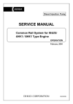
No.
Terminal Name
Content
No.
Terminal Name
Content
B-45 TWV-B
INJECTOR B
B-52 LOL-SW
LOW OIL LEVEL SW
B-46 PB-VCC
BOOST PRESSURE VCC
B-53 —
—
B-47 PFUEL-VCC
RAIL PRESSURE VCC
B-54 —
—
B-48 POIL-VCC
OIL PRESSURE VCC
B-55 —
—
B-49 EGR-VCC
EGR POSITION VCC
B-56 TWV-C
INJECTOR C
B-50 VNTPOS-VCC
VNT POSITION VCC
B-57 TWV-E
INJECTOR E
B-51 G-VB
CAM ANGLE VB
B-58 TWV-A
INJECTOR A
< NOTE >
• *1: In case of connecting to outside wiring, note that this terminal is connected to +B inside ECU.
•
*2: This terminal is unused.
•
N/A: Component is not mounted (circuit pattern only).
-46-