1
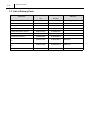
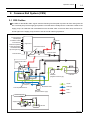
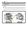
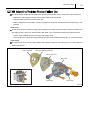
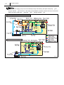
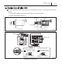
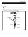
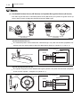
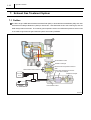
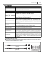
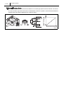
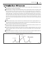
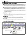
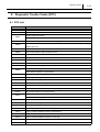
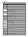
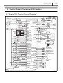
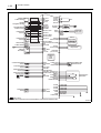
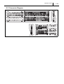
For Authorized Service Dealers Only
ISUZU N-Series 4HK1 Engine
Common Rail System (CRS) Service
Manual
Issued : November 2011
50000057E
© 2011 by DENSO CORPORATION
All rights reserved. This material may not be reproduced
or copied, in whole or in part, without the written
permission of DENSO Corporation.
Table of Contents
Table of Contents
Operation Section
1. Applicable Vehicles and Parts Information
1.1
Outline . . . . . . . . . . . . . . . . . . . . . . . . . . . . . . . . . . . . . . . . . . . . . . . . . . . . . . . . . . . . . . . . . . . . . . . . . . . . . . . . 1-1
1.2
Applicable Vehicle . . . . . . . . . . . . . . . . . . . . . . . . . . . . . . . . . . . . . . . . . . . . . . . . . . . . . . . . . . . . . . . . . . . . . . . 1-1
1.3
List of Primary Parts . . . . . . . . . . . . . . . . . . . . . . . . . . . . . . . . . . . . . . . . . . . . . . . . . . . . . . . . . . . . . . . . . . . . . 1-2
2. Common Rail System (CRS)
2.1
CRS Outline. . . . . . . . . . . . . . . . . . . . . . . . . . . . . . . . . . . . . . . . . . . . . . . . . . . . . . . . . . . . . . . . . . . . . . . . . . . . 1-3
3. Supply Pump
3.1
Outline . . . . . . . . . . . . . . . . . . . . . . . . . . . . . . . . . . . . . . . . . . . . . . . . . . . . . . . . . . . . . . . . . . . . . . . . . . . . . . . . 1-4
3.2
3.3
3.4
4. Rail
4.1
Outline . . . . . . . . . . . . . . . . . . . . . . . . . . . . . . . . . . . . . . . . . . . . . . . . . . . . . . . . . . . . . . . . . . . . . . . . . . . . . . . . 1-9
4.2
Rail Pressure Sensor. . . . . . . . . . . . . . . . . . . . . . . . . . . . . . . . . . . . . . . . . . . . . . . . . . . . . . . . . . . . . . . . . . . . . 1-9
4.3
5. Injectors
5.1
Outline . . . . . . . . . . . . . . . . . . . . . . . . . . . . . . . . . . . . . . . . . . . . . . . . . . . . . . . . . . . . . . . . . . . . . . . . . . . . . . . 1-11
6. Control System Parts
6.1
Engine ECU. . . . . . . . . . . . . . . . . . . . . . . . . . . . . . . . . . . . . . . . . . . . . . . . . . . . . . . . . . . . . . . . . . . . . . . . . . . 1-13
6.2
7. Exhaust Gas Treatment System
7.1
Outline . . . . . . . . . . . . . . . . . . . . . . . . . . . . . . . . . . . . . . . . . . . . . . . . . . . . . . . . . . . . . . . . . . . . . . . . . . . . . . . 1-16
7.2
7.3
8. Diagnostic Trouble Codes (DTC)
8.1
DTC List. . . . . . . . . . . . . . . . . . . . . . . . . . . . . . . . . . . . . . . . . . . . . . . . . . . . . . . . . . . . . . . . . . . . . . . . . . . . . . 1-21
9. Control System Component Information
9.1
Engine ECU Terminal Layout Diagrams . . . . . . . . . . . . . . . . . . . . . . . . . . . . . . . . . . . . . . . . . . . . . . . . . . . . . 1-27
9.2
Connector Diagram . . . . . . . . . . . . . . . . . . . . . . . . . . . . . . . . . . . . . . . . . . . . . . . . . . . . . . . . . . . . . . . . . . . . . 1-29
Table of Contents
Operation Section
1– 1
1. Applicable Vehicles and Parts Information
1.1 Outline
As a result of a model change to the ISUZU 4HK1 engine beginning from May 2010, the Common Rail System (CRS) has also changed. This manual describes items specific to the parts used in the CRS for the
4HK1 engine. For CRS basics, refer to the "COMMON RAIL SYSTEM SERVICE MANUAL -OPERATION
(Doc ID: 00400534EA)."
Compliance with Exhaust Gas Regulations
The CRS for the 4HK1 engine has undergone the following improvements to comply with US10 exhaust gas
regulations.
Combustion Improvements
• System pressure: Increased to 200 MPa
• Supply pump: Operating pressure of 200 MPa, uses positive pressure system
• Rail: Operating pressure of 200 MPa
• Injectors: Uses the G3 type
Improved Post-Processing
• Particulate Matter (PM) reduction: Diesel Particulate Filter (DPF)
• NOx Reduction: Urea Selective Catalytic Reduction (SCR)
1.2 Applicable Vehicle
Vehicle Manufacturer
ISUZU
Vehicle Name
Engine Type
Exhaust Volume
N SERIES
4HK1
5.2 L
Production Start
Date
May 2010
Operation Section
1– 2
1.3 List of Primary Parts
DENSO Part Num-
Manufacturer Part
ber
Number
Supply Pump
294000-112#
8-98081771-2
Rail
095440-155#
8-98081768-0
Injector
295050-032#
8-98110607-2
Engine ECU
275800-875#
8-98160981-2
Crankshaft Position Sensor
949979-031#
8-97606943-0
Cylinder Recognition Sensor
949979-169#
8-98019024-0
Fuel Pressure Sensor
499000-829#
8-98105928-0
265600-125#
8-98004329-0
DPF Side
265600-126#
8-98004330-0
SCR Side
104990-101#
8-97359985-2
Part Name
Exhaust Gas Temperature Sensor
Exhaust Gas Temperature Sensor
Differential Pressure Sensor
Remarks
HP4 Supply Pump
G3 Type
Operation Section
1– 3
2. Common Rail System (CRS)
2.1 CRS Outline
The CRS for the ISUZU 4HK1 engine uses the following fuel flow path to prevent air from mixing with the
fuel. The feed pump for the supply pump draws in fuel that is then initially sent to a main filter outside of the
supply pump. Air inside the fuel is released from the air bleed valve on the main filter. Next, the fuel is returned again to the supply pump, and then sent to the rail under high pressure.
Fuel Temperature
Vehicle Speed
Accelerator Position
Boost Pressure
Intake Air Temperature
Coolant Temperature
Crankshaft Position
Injector
Engine ECU
Rail Pressure Sensor
Cylinder Recognition Signal
Pressure Limiter
Intake Air Mass
Rail
Suction Control Valve
(SCV)
Supply Pump
Sub-Filter
(Negative Pressure Type)
to Fuel Addition
Valve (DPF)
Suction
Air Bleed Valve
Fuel Temperature Sensor
Fuel Tank
Main Filter
(Positive Pressure Type)
Discharge
Feed
Return
Conventional Supply Pump
to Rail
Supply Pump
Fuel Filter
Fuel Tank
Q006718E
1– 4
Operation Section
3. Supply Pump
3.1 Outline
The supply pump used with the ISUZU 4HK1 engine is an HP3 type adapted to positive pressure filter use.
In comparison to conventional supply pumps, the 4HK1 engine supply pump includes a feed pump outlet
port, and main filter pump inlet port. Positive pressure is applied to the main filter by sending fuel from the
feed pump to the main filter. In addition, the supply pump uses a normally open SV3 type Suction Control
Valve (SCV).
Fuel Inlet (from Main Filter)
Suction Control Valve (SCV)
Suction Control Valve
(SCV)
Fuel Outlet
(Overflow,
to Fuel Tank)
Fuel Outlet
(to Main Filter)
Fuel Outlet
(Overflow, to Fuel Tank)
Supply Pump Adapted
to Positive Pressure Filter Use
Fuel Inlet
(from Sub-Filter)
Fuel Temperature Sensor
Fuel Inlet
Conventional Supply Pump
Q006719E
Operation Section
1– 5
The 4HK1 engine CRS has been adapted to positive pressure filter use to achieve the following effects:
• Stabilize the fuel supply by placing the fuel filter under positive pressure
• Suppress filter clogs and increasing filter life
• Reduce diagnostic abnormalities caused by pressure fluctuations that arise when air intermixing is suppressed
Rear Cover
A rear cover has been added to supply pumps adapted to positive pressure filters since the fuel drawn into
the supply pump is sent to an external main filter. Rear cover construction features the following items:
• A relief valve to adjust the fuel returning to the supply pump
• A check valve to increase priming performance to the newly added fuel flow path (i.e., to the main filter)
Feed Pump
The feed pump cover and feed pump plate have changed. Moreover, the discharge port on the feed pump
plate is blocked off.
Feed Pump Plate
Discharge-Side Port Obstruction
Feed Pump Cover
Rear Cover
Rear Cover
Relief Valve
Check Valve
Q006720E
1– 6
Operation Section
In a conventional supply pump, fuel is sent directly through the following flow path: feed pump
plunger chamber
SCV
rail. However, in the supply pump adapted to positive pressure filter use, the fuel flow
path is as follows: feed pump
main filter
SCV
plunger chamber
rail.
Flow Path for Supply Pump Adapted to Positive Pressure Filter Use
Flow Path for a Conventional Supply Pump
Q004898E
Operation Section
1– 7
The SCV used with the ISUZU 4HK1 engine is a normally open SV3 type. The SV3 type has the following
features:
• A more compact design compared to the SV1 type due to a smaller solenoid
• Improved valve sliding performance
Solenoid
Valve Body
Valve Spring
Needle Valve
Armature
<Cross-Sectional Diagram>
<External View>
Q006721E
Plunger
Needle Valve
Supply Pump
Short Duty ON Duration
Large Valve Opening
Large Suction Quantity
Large Valve
Opening
Cylinder
Long Duty ON Duration
Small Valve Opening
Small Suction Quantity
Small Valve
Opening
Cylinder
Q006722E
Operation Concept Diagram
1– 8
Operation Section
The fuel temperature sensor detects the fuel temperature, and sends corresponding signals to the engine
ECU. The ECU then uses the signal information to calculate an injection correction suited to the fuel temperature.
<Reference: Temperature/Resistance Characteristics>
Temperature (
)
Resistance (k
)
Fuel Temperature Sensor
Q006723E
Operation Section
1– 9
4. Rail
4.1 Outline
Compared to a conventional rail, the rail used with the ISUZU 4HK1 engine is adapted to high pressure (200
MPa). The rail distributes fuel sent from the supply pump to each injector.
Fuel Inlet
Pressure Limiter
to Injectors
Rail Pressure Sensor
Q006724E
4.2 Rail Pressure Sensor
The rail pressure sensor detects fuel pressure inside the rail. There are two rail pressure sensors to provide
a backup in case of a malfunction. In addition, the output signal for each sensor system is offset.
Rail Pressure (MPa)
Q006725E
1– 10
Operation Section
The pressure limiter used with the ISUZU 4HK1 engine is adapted to a pressure of 200 MPa. The pressure
limiter opens to release fuel from the rail when the internal pressure becomes abnormally high. Pressure
limiter construction and characteristics are as shown in the figure below.
Housing
Spring
Valve
Open Valve
to Fuel Tank
from Rail
Closed Valve
Valve Body
Q004915E
Operation Section
1– 11
5. Injectors
5.1 Outline
The 4HK1 engine CRS uses G3 type injectors. G3 injectors are designed to support a system pressure of
200 MPa, to improve responsiveness, and to increase resistance against foreign material adherence to the
nozzle.
G3 type operation and QR code (ID code) injection quantity corrections are the same as for G2 type with
conventional QR codes. (However, the QR code correction points differ.)
QR Code
ID Codes
High-Pressure Fuel
(from Rail)
Solenoid Valve
Control Chamber
Command Piston
Pressure Pin
Nozzle Spring
Nozzle Needle
Q006726E.
Operation Section
Injection Quantity Q
1– 12
10 Correction Points
Actuation Pulse Width TQ
Q006727E
Correction Points Using QR Codes
Operation Section
1– 13
6. Control System Parts
6.1 Engine ECU
The engine ECU conducts overall engine control. The engine ECU for the ISUZU 4HK1 engine is mounted
in the cabin, and contains a built-in injector actuation circuit, thereby eliminating the Electronic Drive Unit
(EDU).
Q006728
1– 14
Operation Section
(1) Crankshaft Position Sensor (NE Sensor) and Cylinder Recognition Sensor (G Sensor)
• The 4HK1 engine CRS uses a crankshaft position sensor (NE sensor) and cylinder recognition sensor (G
sensor). Both sensors are Magnetic Resistance Element (MRE) types.
Crank Position Sensor
(NE Sensor)
Cylinder Recognition Sensor
(G Sensor)
Q006729E
Crankshaft Position Sensor
The crankshaft position sensor detects the crankshaft angle. The pulsar has 56 teeth (separated at 6°
intervals, with four missing teeth to detect Top Dead Center [TDC] for cylinders no. 1 and no. 4).
<Circuit Diagram>
Engine ECU
Sensor
Four Missing Teeth
NE Input Circuit
Pulsar
Q006730E
Cylinder Recognition Sensor (G)
The cylinder recognition sensor identifies the engine cylinders. The pulsar has five teeth (recognition
of TDC for each cylinder + recognition of cylinder no. 1).
Pulsars
Cylinder No. 1
Recognition
<Circuit Diagram>
Engine ECU
Sensor
G Input Circuit
Q006731E
Operation Section
1– 15
• The 4HK1 engine CRS is equipped with a fuel pressure sensor to detect fuel pressure between the feed
pump outlet on the supply pump, and the main filter. Sensor output determines correction control for the
fuel addition valve, and whether a main filter clog exists. The fuel pressure sensor is a semiconductor type
device that uses a characteristic of silicone crystals in which electrical resistance changes when the pressure applied to the crystals is varied.
Output Voltage (V)
Engine ECU
Fuel Pressure (MPa)
Q006732E
(3) Engine Oil Pressure Sensor
• The engine oil pressure sensor detects engine oil pressure. If engine oil pressure reaches an abnormally
high value, the sensor stops the engine.
Output Voltage (V)
Engine ECU
Q006733E
1– 16
Operation Section
7. Exhaust Gas Treatment System
7.1 Outline
The 4HK1 engine CRS adds a Diesel Particulate Filter (DPF) to eliminate Particulate Matter (PM), and uses
urea Selective Catalytic Reduction (SCR) to reduce NOx. Urea SCR adds urea to the exhaust gas, and the
SCR catalyst reduces the NOx. The exhaust gas temperature sensor and differential pressure sensor used
in the 4HK1 engine exhaust gas treatment system are made by DENSO.
Fuel Addition Valve
Oxidation Catalyst
Exhaust Gas Temperature Sensor
Differential Pressure Sensor
DPF
Exhaust Gas Temperature Sensor
Urea SCR Catalyst
Oxidation Catalyst
Urea SCR
ECU
Urea Feed Device
Urea Addition Valve
Urea Tank
Q006734E
Operation Section
Part
1– 17
Function
Conducts HC and CO purification, as well as NO x oxidation (NO Å® NO2).
(Adding NO2 promotes NOx reduction.)
Diesel Particulate Filter (DPF) Traps PM and conducts PM oxidation treatment.
Urea SCR Catalyst
Oxidation Catalyst (Post-Urea
SCR Catalyst)
Exhaust
Gas
Temperature
Sensor (DPF)
Uses urea added to the exhaust gas to reduce the NOx.
Purifies any urea (ammonia) not used in NOx reduction.
Measures the exhaust gas temperature at the DPF, and then outputs corresponding signals to the engine ECU. The engine ECU controls DPF regeneration based on the aforementioned signals.
Measures the difference in exhaust gas pressure across the DPF, and then
outputs corresponding signals to the engine ECU. The engine ECU calcu-
Differential Pressure Sensor
lates the quantity of PM accumulated in the DPF based on the aforementioned signals, and then determines whether or not to conduct PM
regeneration.
Mounted upstream of the urea SCR catalyst to measure the NOx concentra-
NOx Sensor
Exhaust
Gas
tion in the exhaust gas before passing through the catalyst.
Temperature Mounted upstream of the urea SCR catalyst to measure the exhaust gas
Sensor (Urea SCR)
temperature before passing through the catalyst.
Urea Addition Valve
Adds urea to the exhaust gas based on signals from the urea SCR ECU.
Urea Feed Device
Draws urea from the urea tank that is then pumped to the urea addition
valve. The pumping pressure is based on control from the urea SCR ECU.
Calculates the optimal urea addition quantity based on signals from the NOx
sensor, exhaust gas temperature sensor (urea SCR), etc. Controls the urea
Urea SCR ECU
feed device and urea addition valve so that the optimal amount of urea is
added to the system. In addition, outputs urea SCR system diagnosis to the
engine ECU.
Exhaust Gas Temperature Sensor
The exhaust gas temperature sensor detects the exhaust gas temperature in the vicinity of the catalyst. A
thermistor is used for actual temperature detection.
Temperature - Resistance Characteristics
265600-125#
(DPF Side)
265600-126#
(SCR Side)
Temperature
Resistance Value
*The only difference between the two
sensors is the thread pitch.
(The specifications are the same.)
Q006735E
1– 18
Operation Section
The differential pressure sensor detects the difference in exhaust gas pressure across the DPF. The sensor
is a semiconductor type device that uses a characteristic of silicone crystals in which electrical resistance
changes when the pressure applied to the crystals is varied.
Engine ECU
Fuel Pressure (kPa)
Q006736E.
Operation Section
1– 19
The following is an outline of PM regeneration control in the 4HK1 engine CRS. PM regeneration can be
performed both manually and automatically.
PM regeneration is normally conducted automatically when the system determines that a set quantity of PM
has accumulated in the DPF. However, there are cases in which PM regeneration does not take place automatically due to driving conditions. When PM is not being regenerated automatically, the following two
indicator lights flash: 1) the light built into the switch for the exhaust gas purification device, and 2) the exhaust gas purification device light located inside the meter panel. These indicator lights are alerts prompting
the user to press the exhaust gas purification device switch and begin manual PM regeneration. When an
alert occurs, press the exhaust gas purification device switch near the driver's seat to manually start PM
regeneration.
Control
The accumulated quantity of PM is inferred from the differential pressure sensor signals (difference in exhaust gas pressure across the DPF). PM regeneration occurs when the accumulated PM quantity is determined to be high (a large differential pressure across the DPF).
In PM regeneration mode, after-injection has been added to the normal injection pattern (pre-injection, main
injection). Injection is also performed from the fuel addition valve.
The actual control sequence adds the after-injection first to raise the catalyst temperature. Next, when the
catalyst temperature reaches a set value, injection occurs from the fuel addition valve, and full-scale regeneration begins.
Regeneration judgments and injection control are conducted by inferring the catalyst temperature base on
signals from the exhaust gas temperature sensors before and after each catalyst.
Top Dead Center (TDC)
Main Injection
Pre-Injection
Q006737E.
1– 20
Operation Section
Urea SCR adds an aqueous urea solution to the exhaust gas, and the SCR catalysts reduces the NOx. The
aqueous urea solution is not used as is during NOx reduction. In actuality, the ammonia produced when the
solution undergoes hydrolysis is used to reduce the NOx. A system that contains an aqueous urea solution
is used due to the inherent danger of mounting a source of ammonia directly on the vehicle.
The urea SCR ECU controls the urea SCR based primarily on the exhaust gas temperature and the NO x
concentration in the exhaust gas. Ammonia is generated from the aqueous urea solution by using the exhaust gas heat to conduct hydrolysis. As such, the following values are required to add the solution from
the urea addition valve into the exhaust gas: 1) the quantity of urea that will undergo hydrolysis, calculated
from the exhaust gas temperature; and 2) the optimal quantity of solution to be added, calculated from the
NOx concentration in the exhaust gas.
(1) NOx Reduction Mechanism
• An oxidation catalyst prior to the urea SCR that initially oxidizes NO into NO2. This catalyst promotes the
NOx reduction reaction when NO 2 increases.
• Adds the aqueous urea solution to the exhaust gas after it has passed through the DPF. The added aqueous urea solution is hydrolysized by exhaust gas heat and converted into ammonia and CO2.
• Uses the ammonia generated from the aqueous urea solution to reduce and convert the NOx into N2 (nitrogen) and H 2O (water).
• Purifies any ammonia not used in NO x reduction.
Oxidation Catalyst
NNO Oxidized into NO2
Aimed at the NOX
reduction reaction (1)
in the urea SCR catalyst.
DPF
Urea Addition Valve
Ammonia Generation
Urea SCR Catalyst
NOX Reduction
An aqueous urea solution is hydrolysized u
sing the exhaust gas heat to generate
ammonia.
Four reduction reactions are triggered in the catalyst
to reduce the NOX. However, the reaction (1)
is the most efficient.
Reaction in the Urea SCR Catalyst
Reduction
Reaction
Catalyst
Q004928E
Operation Section
1– 21
8. Diagnostic Trouble Codes (DTC)
8.1 DTC List
DTC
Detection Item
P000F
Rail pressure too low
P0016
Crankshaft position-intake camshaft position correlation bank 1
P0027
Exhaust brake valve stick
Exhaust throttle valve stick
P003A
P0045
Variable Geometry Turbo (VGT) module wiping too wide error
VGT module motor circuit short and GND short/position control abnormal/power supply
voltage high error
P0046
VGT module control response abnormal
P006E
VGT module power supply voltage low error
P0079
Exhaust throttle GND short
P007C
Charge Air Cooler (CAC) out temperature sensor circuit low voltage
P007D
CAC out temperature sensor circuit high voltage
P0080
Exhaust throttle +B short
P0087
Rail pressure low during power enrichment
Rail pressure too high
P0088
Fuel pressure regulator 1 performance
P0089
Rail pressure exceeds high upper limit
P0091
Rail fuel pressure regulator solenoid 1 control circuit
P0092
Rail fuel pressure regulator solenoid 1 control circuit
P0093
Rail fuel pressure low during idle or deceleration fuel cut-off
P0097
Intake manifold temperature sensor 2 circuit low
P0098
Intake manifold temperature sensor 2 circuit high
P00AF
VGT module memory access abnormal
Mass Air Flow (MAF) meter rationality low
P0101
MAF meter rationality high
P0102
MAF meter circuit low
P0103
MAF meter circuit high
P0112
Intake air temperature sensor circuit low
P0113
Intake air temperature sensor circuit high
P0116
Engine coolant temperature sensor performance
P0117
Engine coolant temperature sensor circuit low
P0118
Engine coolant temperature sensor circuit high
P011C
CAC temperature outlet sensor surveillance
P0126
Engine coolant temperature insufficient for stable operation
1– 22
Operation Section
DTC
Detection Item
P0128
Engine coolant temperature below thermostat regulating temperature
P0171
Injector quantity lean performance
P0172
Injector quantity rich performance
P0181
Fuel temperature sensor intermediate hold
P0182
Fuel temperature sensor A circuit low
P0183
Fuel temperature sensor A circuit high
Rail pressure sub-sensor signal keeping the middle range
P018B
Rail pressure sub-sensor performance 1
Rail pressure sub-sensor performance 2
P018C
Rail pressure sub-sensor circuit low voltage
P018D
Rail pressure sub-sensor circuit high voltage
Rail pressure sensor signal keeping the middle range
P0191
Rail pressure sensor performance 1
Rail pressure sensor performance 2
P0192
Rail pressure sensor circuit low voltage
P0193
Rail pressure sensor circuit high voltage
P0201
TWV 1 output open load injector #1 coil open
P0202
TWV 4 output open load injector #2 coil open
P0203
TWV 2 output open load injector #3 coil open
P0204
TWV 3 output open load injector #4 coil open
P020A
Injector #1 quantity increase failure
Injector #1 quantity decrease failure
P020B
Injector #2 quantity increase failure
Injector #2 quantity decrease failure
P020C
Injector #3 quantity increase failure
Injector #3 quantity decrease failure
Injector #4 quantity increase failure
P020D
Injector #4 quantity decrease failure
Engine overrun
P0219
Engine overrun 2
P0234
Turbo/supercharger engine overboost
P0237
Turbo/supercharger boost sensor A circuit low
P0238
Turbo/supercharger boost sensor A circuit high
P0261
Injector #1 (TWV 1) load short (coil short/terminal short)
P0264
Injector #4 (TWV 4) load short (coil short/terminal short)
P0267
Injector #2 (TWV 2) load short (coil short/terminal short)
P0270
Injector #3 (TWV 3) load short (coil short/terminal short)
P0299
Turbo/supercharger engine underboost
P02E2
ITHR DC motor output open load motor open load
Operation Section
DTC
P02E3
Detection Item
ITHR DC motor output short to battery/short to GND motor short
Intake throttle stuck closed
P02E7
Intake throttle stuck open
Intake throttle open learning error
Intake throttle closed learning error
P02E8
Intake throttle position too low
P02E9
Intake throttle position too high
P0300
Engine misfire detected
P0301
Cylinder 1 misfire detected
P0302
Cylinder 2 misfire detected
P0303
Cylinder 3 misfire detected
P0304
Cylinder 4 misfire detected
P0335
Crankshaft position sensor A circuit
P0336
Crankshaft position sensor A performance
P0340
Intake camshaft position sensor circuit bank 1
P0341
Intake camshaft position sensor performance bank 1
P0381
Wait to start light control module internal circuit (short to BATT)
Wait to start light control module internal circuit (open load/short to GND)
P0401
MAF meter performance (Exhaust Gas Recirculation [EGR] negative deviation)
P0402
MAF meter performance (EGR positive deviation)
EGR duty error
P0403
EGR brushless motor circuit too high
EGR brushless motor circuit too low
EGR brushless motor circuit too open
P0404
EGR open position performance
P0405
EGR brushless motor position sensor signal invalid low
P0406
EGR brushless motor position sensor signal invalid high
P040B
EGR gas sensor performance
P040C
EGR gas temperature too low
P040D
EGR gas temperature too high
P041B
EGR gas sensor 2 performance
P041C
EGR gas temperature 2 too low
P041D
EGR gas temperature 2 too high
P0420
DPF deterioration 2
P042E
EGR closed position performance
P046C
EGR closed learning
P0500
Vehicle speed sensor circuit
P0506
Low target idle speed
P0507
High target idle speed
1– 23
1– 24
Operation Section
DTC
Detection Item
P0512
Starter switch short to BATT
P0522
Oil pressure sensor signal too low
P0523
Oil pressure sensor signal too high
P0545
Exhaust gas temperature before oxidation catalyst too low
P0546
Exhaust gas temperature before oxidation catalyst too high
P0562
System low voltage status determination
P0563
System high voltage status determination
P0567
Cruise control resume switch determination
P0568
Cruise control set switch determination
P0571
Cruise control brake switch determination
P0602
QR code error
P0606
Engine ECU processor (main CPU fault)
Engine ECU processor (watchdog IC fault)
P062F
Control module long term memory performance
P0642
Battery 5 V reference 1 circuit low
P0643
Battery 5 V reference 1 circuit high
Glow plug module control circuit
P064C
Glow plug module INTST
Glow plug module MEEPST
P0650
Malfunction Indicator Lamp (MIL) control circuit monitoring (short to BATT)
MIL control circuit monitoring (open load/short to GND)
P0652
Battery 5 V reference 2 circuit low
P0653
Battery 5 V reference 2 circuit high
P0671
Cylinder 1 glow plug circuit
P0672
Cylinder 2 glow plug circuit
P0673
Cylinder 3 glow plug circuit
P0674
Cylinder 4 glow plug circuit
P0687
Main relay diagnostics; main relay stuck closed
P0698
Battery 5 V reference 3 circuit low
P0699
Battery 5 V reference 3 circuit high
P0700
Transmission control module requested MIL illumination monitoring
P1072
Compressor outlet temperature sensor circuit low voltage
P1073
Compressor outlet temperature sensor circuit high voltage
P1076
CAC in temperature sensor circuit low voltage
P1077
CAC in temperature sensor circuit high voltage
P1078
CAC temperature inlet sensor surveillance
Supply pump protection
P1085
P1102
Supply pump exchange
Rail pressure sensor performance (correlation abnormal)
Operation Section
DTC
Detection Item
P1125
Accelerator Pedal Position (APP) system
P113A
O2 signal of NOx sensor rationality
P1236
CAC performance
P1259
Rail fuel pressure low during power enrichment
P1261
Capacitor charge-up circuit malfunction (insufficient charge)
Capacitor charge-up circuit malfunction (excessive charge)
P1463
DeNOx-DS error for SVS lighting request
P1470
DPF exhaust presser performance
P1471
DPF regeneration insufficiency
P160B
Q DATA cross check error
P2002
DPF deterioration (II)
P2032
Exhaust gas temperature before DPF too low
P2033
Exhaust gas temperature before DPF too high
P20C9
DeNOx-DS error for MIL lighting request
P20CB
Exhaust injector circuit GND short/open load
P20CC
Exhaust injector circuit BATT short
Exhaust injector circuit load short
P20CF
P20DE
Exhaust injector performance
Exhaust injector pressure sensor performance high
Exhaust injector pressure sensor performance low
P20DF
Exhaust injector pressure sensor circuit low voltage
P20E0
Exhaust injector pressure sensor circuit high voltage
P20E2
Exhaust gas temperature sensor surveillance
P2122
Accelerator pedal position sensor no. 1 low range
P2123
Accelerator pedal position sensor no. 1 high range
P2127
Accelerator pedal position sensor no. 2 low range
P2128
Accelerator pedal position sensor no. 2 high range
P2138
Accelerator pedal position sensor no. 1 & 2 correlation check
P2146
COM 1 output open load; Both TWV 1 and 3 (and 5) open load
P2147
COM 1 output short to GND; TWV 1 or 3 (or 5) output short to GND
P2148
COM 1 output short to BATT; TWV 1 or 3 (or 5) output short to BATT
P2149
COM 2 output open load; Both TWV 2 or 4 (or 6) open load
P2150
COM 2 output short to GND; TWV 2 or 4 (or 6) output short to GND
P2151
COM 2 output short to BATT; TWV 2 or 4 (or 6) output short to BATT
P2199
THA-THA 2 sensor surveillance
P2227
Barometric pressure (BARO) sensor performance
P2228
Barometric pressure (BARO) sensor circuit low voltage
P2229
Barometric pressure (BARO) sensor circuit high voltage
P2262
Turbo/supercharger engine underboost
1– 25
1– 26
Operation Section
DTC
P2263
Detection Item
VGT slow response up side
VGT slow response down side
P226B
P2413
Turbo/supercharger engine overboost
EGR slow response ON
EGR slow response OFF
P2428
Exhaust gas temperature sensor before oxidation catalyst too high
Exhaust gas temperature sensor before oxidation catalyst too low
P244B
DPF PM over accumulation
P244C
DPF deterioration
P244D
Exhaust gas temperature sensor before DPF too high
Exhaust gas temperature sensor before DPF too low
P2453
DPF pressure sensor performance
P2454
Exhaust gas pressure reference too low
P2455
Exhaust gas pressure reference too high
P2457
EGR cooler inferiority
P2459
DPF regeneration excessive frequency
P2463
DPF trip over accumulation
P254C
Auxiliary engine RPM sensor circuit low
P254D
Auxiliary engine RPM sensor circuit high
P2564
VGT hole IC sensor circuit low
P2565
VGT hole IC sensor circuit high
P256C
Idle Air Control (IAC) valve control circuit low voltage
P256D
IAC valve control circuit high voltage
P268A
QR code not programmed
U0001
CAN bus 2 reset counter overrun
U0073
CAN bus reset counter overrun
U0101
Lost CAN communication (CAN SOH) with TM control system
U0106
Glow plug module communication failure
U010C
VGT module communication failure
U010E
DeNOx-DS communication time-out
U0121
CAN ABS SOH diagnostic
U0307
GPCM engine ID diagnostic
Operation Section
1– 27
9. Control System Component Information
9.1 Engine ECU Terminal Layout Diagrams
P/N SW
ACG
START
ON
KEY SW
C
Starter Relay
ACC
B
Main Relay
BATT
A
Accelerator
Position
Sensor
APS2 APS1
Vehicle
Speed Sensor
B
PTO
Accelerator
Position
Sensor
DPFSOL
EXBCUT-SW
PACL-VCC
PACL
PACL-GND
Exhaust Brake
PTO Disable SW
Remote PTO Set
Remote PTO Resume
PTO Set Speed A SW
PTO Set Speed B SW
CAB Control Disable SW
Ignore Brake/Clutch SW
Cruise Main (ON/OFF)
Cruise Resume/Accel
Cruise Set/Coast
PTO LAMP
M-REL
M-REL
+B
+B
+B
BATT
VSS
APS1-VCC
APS1
APS1-GND
APS2-VCC
APS2
APS2-GND
IDLUP-VCC
IDLUP
IDLUP-GND
Idle Up
Volume
PTO SW
STA-SW
STA-REL
IG1-SW
OFF
+
Battery
-
B
Starter Motor
PTO Tap Down
MIL
GL-L
CANH
CANL
TACHO
VSOUT1
DPF Exhaust
Throttle
Cut Relay
ABS
Meter
Malfunction Indicator Lamp
B
Glow Lamp
Twisted
Pair
SAEJ1939-11 Compliant
Twisted Pair
Twisted
Pair
Tacho
Vehicle Speed
PWM Output
VGS C/U
AT
Controller
MT Vehicles Only
Glow Plug
Control Module
EXB-SW
A
C
Glow Plug
PTODIS-SW
RSET-SW
RRES-SW
SSPA-SW DPFD-VCC
DPFD
SSPB-SW
CCDIS-SW DPFD-GND
IGBC-SW
THDOC
CRM-SW THDOC-GND
CRR-SW
CRS-SW
THCSF
DPF Differential
Pressure Sensor
Exhaust Gas
Temperature Sensor-1
(Oxidation Catalyst)
Exhaust Gas
Temperature Sensor-2
(SCR)
THCSF-GND
PTO Tap Up
A
A
Exhaust
Soknoid Valve
PTOEN-SW LOCOL-SW
PTOEN-REL IDESEN-SW
PTOFB-SW
Enable Relay PTO Feedback SW
IDM1
IDM2
Magnetic Valve
Brake1 (Normally Open) BK1-SW COMMON1
Brake2 (Normally Closed) BK2-SW
TWV-A
Clutch SW (MT Vehicles)
TWV-C
CL-SW
DPF Regeneration DPFREG-SW COMMON2
Air Conditioner AC-SW
TWV-B
TWV-D
Magnetic Clutch
:Option Circuit
Terminals with no external circuit commands written in parenthesis are auxiliary circuits.
Low Coolant Level SW
Idle Engine Stop Enable SW
M+
M-
Diesel Throttle
DC Motor
Injector #1
Injector #4
Injector #3
Injector #2
Q006845E
Operation Section
1– 28
Crankshaft
Position Sensor
Cylinder
Recognition Sensor
Manifold Absolute
Pressure sensor
Rail Pressure
Sensor1
NE-VCC
SCVHI
NE
SCVHI
NE-GND
SCVLO
G-VCC
SCVLO
G
G-GND
EXTPIP+
PB-VCC
EXTPIPPBOOST
PB-GND
PFUEL1-VCC
ISOH
ISOL
PFUEL1
SCV
Twisted Pair
Fuel Addition Valve
ISO CAN
SAE.CON
DCU
PFUEL1-GND
PFUEL2-VCC
Rail Pressure
Sensor2
Diesel Throttle
Position Sensor
A
Mass Air
Flow Meter
CAC In
Temperature
THCAI1
PFUEL2 THCAI1-GND
PFUEL2-GND
ITH-VCC THCAO1-GND
ITH
ITH-GND
THCOT
THCOT-GND
MAF
MAF-GND
(THCAO2)
THA
THA-GND
CAC Out
Temperature
Compressor Outlet
Temperature
(THCAO2-GND)
Atmospheric
Pressure
Sensor
(BARO)
Coolant Temperature
Sensor
Fuel Temperature
Sensor
EGR Temperature
Sensor (IN)
EGR Temperature
Sensor (OUT)
Oil Pressure
Sensor
THW
EXPS-VCC
THW-GND
EXPS
EXPS-GND
THL
THL-GND
Fuel Addition Valve
Pressure Sensor
THEGRI
THEGRI-GND
THEGRO EGRPOS-VCC
THEGRO-GND EGRPOS-U
EBM-U
EGRPOS-V
IMT
EBM-V
IMT-GND
EGRPOS-W
EBM-W
EGRPOS-GND
P-GND
P-GND
P-GND
POIL-VCC
POIL
P-GND
POIL-GND
GND
GND
CASE-GND
:Option Circuit
Terminals with no external circuit commands written in parenthesis are auxiliary circuits.
EGR Valve Drive DC
Brushless Motor
Power GND
Power GND
Power GND
Power GND
Signal GND
Signal GND
Case GND
Q006846E
Operation Section
1– 29
9.2 Connector Diagram
Q006847
Service Division DENSO CORPORATION
1-1, Showa-cho, Kariya-shi, Aichi-ken, 448-8661, Japan