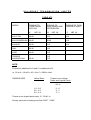
1
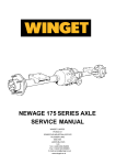
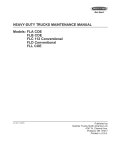
SERVICE MANUAL
SALISBURY 5HA AXLES
WINGET LIMITED
P.O. BOX 41
EDGEFOLD INDUSTRIAL ESTATE
PLODDER LANE
BOLTON
LANCS
TEL: ++ 44 (0) 1204 854650
FAX: ++ 44 (0) 1204 854663
parts@winget .co.uk
[email protected]
www.winget.co.uk
Introduction
Winget Limited gratefully acknowledge the assistance given by GKN Salisbury in
the preparation of this manual, however neither Winget Limited or Salisbury can
be held responsible for any errors or omissions.
The procedures described within this manual should enable experienced service
personnel to strip, repair and re-build Salisbury 5HA series axles fitted to Winget
Site Dumpers in a safe and competent manner. The procedures are not intended
to be used by personnel who are unfamiliar with the product or mechanically
inexperienced.
It is assumed that personnel are aware of the Health & Safety Regulations which
should be applied but the following should act as a reminder.
Whenever possible any repairs or service should be carried out in a clean
environment. If work must be carried out on site or in the field steps should be
taken to ensure that dirt or foreign materials cannot enter the assembly.
Ensure all works tools are in good condition and only use the correct tool for the
job in hand.
Always wear safety spectacles when using soft or hard faced hammers, chisels,
drifts or when using air tools. Wear safety spectacles when cleaning components
or when grinding.
Do not misuse air lines and be aware of the damage compressed air can cause if
misused.
Always make sure lifting equipment is in good condition and the Safe Working
Load exceeds the weight of the component to be lifted.
Always use suitable supports i.e. axle stands or baulks of timber in conjunction
with hydraulic jacks etc. Never rely on hydraulic jacks alone to support a
machine.
Be aware of hot surface temperatures and take care when draining hot oils.
Always dispose of waste oils in accordance with local and national regulations.
Whenever possible always disconnect the battery or battery isolator when
working on the machine to prevent electrical shorts and unauthorised starting.
Refer to the operator's handbook for a guide to the correct sequence for
assembling components and sub-assemblies.
Oils, fuels, silicone sealer etc can cause skin diseases if allowed to contaminate
the skin. Always apply barrier creams, wear suitable protective clothing or when
contamination is unavoidable clean the area with soap and water as soon as
possible. Do not use thinners or other solvents to clean skin.
Health & Safety is a matter of common sense. If common sense is applied
correctly the risk of accidents can be reduced.
Spares for Salisbury Axles fitted to Winget Equipment can only be obtained from
Winget Limited or one of our authorised distributors and not from GKN Salisbury.
Always quote your machine's serial number and model together with axle serial
number and model when ordering spare parts.
5HA series axles are designed to operate under arduous conditions and
providing they are regularly and correctly maintained they will provide long
trouble free service.
The contents of this manual although correct at the time of publication, may be
subject to alteration by the manufacturers without notice and Winget Limited can
accept no responsibility for any errors or omissions contained within the following
pages. Nor can we accept any liability whatsoever arising from the use of this
manual howsoever caused.
Winget Limited operate a policy of continuous product development. Therefore,
some illustrations or text within this publication may differ from your machine.
INDEX
INTRODUCTION
A.
CENTRE SUB ASSEMBLIES
A-1
A-2
B.
DIFFERENTIAL ASSEMBLIES
B-1
B-2
C.
2 Pin Diff Assembly
4 Pin Diff Assembly
HUB ASSEMBLIES
C-1
C-2
C-3
C-4
D.
Shim adjusted centre sub-assemblies.
Collapsible Spacer centre sub-assemblies.
Semi Floating Hub
Semi Floating Outrigger Hub
Fully Floating Hub
End Float Adjustment on 05HA OIMPD Hub
BRAKES
D-1
D-2
D-3
Drum Brakes
Disc Brakes
Oil Immersed Brake (05HA)
E.
INTENTIONALLY BLANK
F.
AXLE SHAFTS
F-1
F-2
F-3
Semi Floating
Semi Floating Outrigger
Fully Floating
G.
GEAR TOOTH CONTACT
H.
TABLES
J.
DIAGRAMS
Section A
CENTRE
HUB ASSEMBLIES
SECTION A.1.
DISMANTLING AND REASSEMBLY OF SHIM ADJUSTED
CENTRE & SUB ASSEMBLIES
This section covers certain 7HA, 4HA, 4HU, 5HA 4HS/5HS, 8HA 8HS, 8HD 10HA and
10HD centre sub assemblies.
DISMANTLING
1.
2.
3.
4.
5.
6.
7.
8.
9.
10.
11.
12.
13.
14.
15.
16.
17.
18.
19.
Drain oil and remove the halfshafts/axle shafts.
Remove carrier cover and gasket - discard gasket, (‘a’ - figure AF1).
Note markings on bearing caps ('a' - figure AF2) and axle casing ('b' - figure
AF2) for use when refitting.
Remove bearing caps using the loosened bolts to ease the caps away from the
bearing. ('c' - figure AF2).
Remove any inclusions from stretcher holes ('d' - figure AF2) and rectify any
damage on edges of holes in order that the carrier stretcher tool will fit correctly.
Check turn buckle on carrier stretcher tool is free and fit tool to carrier ensuring
that pegs locate fully in stretcher hole.
Checking that no foul condition exists rotate turn buckle by spanner in order to
stretch carrier - IMPORTANT - DO NOT STRETCH CARRIER MORE THAN
.010" - .012" MEASURED ACROSS STRETCHER HOLE.
Remove differential assembly complete with ring gear. It may be necessary to
lever the case out of the carrier. In order to prevent damage, do not lever
against stretcher or carrier, but use packing.
Ease off turn buckle and remove spreader.
Remove ring gear from differential case assembly if necessary.
Remove bearing cones from differential case trunnion diameter, if necessary.
Disassemble differential in accordance with appropriate sheet.
Prevent rotation of companion flange by using service tool having pegs locating
in flange bolt holes. Remove the locknut and washer.
Remove companion flange from pinion using withdrawal tool by supporting
pinion inside carrier and tapping flange with hide or other suitable hammer.
Remove pinion complete with inner bearing cone.
Remove oil seal, gasket and oil thrower - discard seal and gasket.
Remove outer bearing cone.
Remove inner and outer bearing cups from carrier. (Extraction slots are provided
in the carrier for ease of removal purposes). Carefully note the shim pack
thickness under both cups. Discard the shims because of possible damage
during removal.
Remove inner bearing cone from pinion using service tool.
CLEAN AND CAREFULLY CHECK ALL COMPONENTS FOR WEAR OR DAMAGE
PRIOR TO REASSEMBLY
REASSEMBLY
20.
21.
22.
23.
Check that pinion and gear are matched in that the serial no's. on the end face
of the pinion and on the outer diameter of the gears are identical. (It should be
noted that marks on the pinion end adjacent to serial number have no
significance in service.)
Assembly inner bearing cone onto pinion using service tool or suitable press.
Select new shim pack the size of that removed from the inner bearing. Insert into
carrier. Press inner bearing cup into housing, using press and suitable adaptor
(if new gear set or bearings are used the shim pack is to be chosen to give the
correct pinion height setting as described later.)
Select new shim pack the size of that removed from the outer bearing. Insert
into carrier. Press outer bearing cup into housing using press and suitable
adaptor (if new gear set or bearings are used the shim pack is to be chosen to
give a bearing preload as stated in table AT2).
NOTES
a. Ensure both cups are pressed and firmly seated into carrier.
b. Take care not to damage face or taper of bearings whilst assembling.
c. Both bearing cups may be assembled together if the appropriate service tool
is available.
24.
25.
26.
27.
28.
29.
30.
31.
32.
Insert pinion and pinion bearing into housing and support in position.
Fit outer bearing cone over pinion and seat into cup.
Fit oil slinger.
Fit new oil seal gasket and oil seal. The seal is to be fitted with the lip facing
inwards. As an aid to assembly and to prevent lip damage, apply a small amount
of grease to lip prior to assembly. The oil seal should be pressed into housing
using a suitable adaptor locating near the outer diameter of the seal.
Fit companion flange. If it is necessary to press or tap the flange into position do
not let flange react against bearing but react against support on pinion head.
Fit washer and new lock nut.
Before tightening locknut apply a small amount of oil to both bearings.
Tighten nut gradually to figure given in table AT3 rotating the pinion assembly
slightly at intervals throughout.
Check the correct positional setting of the pinion is as follows:
a. Check the nominal pinion cone setting distance from table AT1.
b. Check the variation figure marked on the head of the pinion (see figure AF3).
This figure is given in thousandths of an inch.
c. Add these figures to give the actual required pinion cone setting distance.
Example:
Nominal cone distance
Marked variation
Actual required distance
=
=
=
2.500
(+3) + .003
2.503
(-2)
2.500
- .002
2.498
d. Read the differential bearing seat diameter from table AT1.
e. Subtract half the figure at 32(d) from that at 32(c) to give nominal clock
setting height.
Example
32(c)
32(d)
Clock setting height
33.
34.
35.
36.
37.
=
=
2.503
1.500
-------1.003
--------
Using a small magnetic base clock and setting piece or slipblocks set the clock
to the dimension obtained in 32(e). this method of clock setting is shown in
figure AF4.
Ensure the pinion end is free from burrs.
Mount the magnetic base of the clock onto the pinion end so that the stylus
registers in the bottom of the differential bearing bore. This is shown in figure
AF5. The clock can be moved slightly to and fro by turning the pinion in order to
ensure maximum reading is obtained.
Repeat operation on other differential bearing bore.
Add the two readings and halve the result in order to obtain the mean figure. If
the pinion is set correctly a mean reading of zero should be obtained. A negative
reading indicates the pinion is set too high and shims need to be removed from
under the inner pinion bearing cup.
A positive reading indicates that the pinion is set too low and more shims need
to be added under the inner pinion bearing cup.
NOTES
a. The amount of variation away from zero gives the amount of shim
adjustment required.
b. If a change in shim pack is required it is essential that a corresponding
opposite change takes place under the outer pinion bearing cup i.e. if .003"
is removed from the inner bearing cup shim pack to give the correct pinion
height the .003" must be added to the outer bearing cup shim pack. This is in
order to maintain the correct preload for the two bearings as given in table
AT2.
38.
39.
40.
41.
42.
Assemble ring gear onto differential case and bolt together by gradually and
evenly tightening the bolts. Do not tighten one bolt at a time but work on
diametrically opposite bolts. This ensures the ring gear is seated correctly on the
case. It is advised to use Loctite 'studlock' grade or similar locking compound on
the bolt treads. Do not use excessively and remove any surplus. Tighten bolts to
torque figures given in table AT3.
Assemble differential bearing cones to differential case using press and suitable
adaptor. NOTE when pressing second bearing cone onto case, seat first bearing
cone into its cup in order to prevent damage to bearing case etc.
With bearing cups fitted onto cones lower differential case assembly into the
carrier. Take care when meshing gear and pinion not to damage teeth.
Position a dial gauge as shown in figure AF6.
Fit suitable shim packs between the differential bearing cups and carrier on each
side in order to give a reading of .007" on the dial gauge when the gear
backlash is measured. It is important that the pinion is not moved when
measuring ring gear backlash otherwise false results are obtained.
The shim packs should be a resistance fit.
Shims are available in .003", .005", .010" and .030"
NOTE
When using new bearings rotate differential assembly approx. six times whilst
pressing towards each bearing in turn - this is in order to settle bearings.
Following this adjust shim packs if necessary to give resistance fit and repeat
backlash check.
43.
44.
45.
46.
47.
48.
49.
50.
51.
52.
53.
Remove differential assembly together with shim packs. Carefully note to which
end the shim pack relates - add .003" shim to each pack in order to give bearing
preload.
Remove one differential bearing cone from case and fit appropriate shim pack to
case trunnion. Refit bearing cone.
Repeat above on other differential bearing.
Fit carrier stretcher tool to carrier and stretch carrier - IMPORTANT - DO NOT
STRETCH CARRIER MORE THAN .010" - .012" MEASURED ACROSS
STRETCHER HOLES.
Assemble differential assembly together with bearing cups into carrier. It may be
necessary to tap lightly in order to assemble. Do not force assembly into position
as this could cause damage to bearings.
Fit bearing caps noting that markings match with markings on carrier.
Tighten bearing cap bolts to torque figures as stated in table AT3.
Check companion torque to turn figures as stated in table AT2.
Re-fit carrier cover using new gasket. Tighten cover bolts to figure given in table
AT3.
Re-fit half shafts/axle shafts.
Re-fill with oil of correct grade.
SECTION A.2.
DISMANTLING AND REASSEMBLY OF AXLE
CENTRE ASSEMBLIES USING COLLAPSIBLE SPACER
This section covers certain 7HA, 4HA, 4HU, 8HA 8HS, 8HD 10HA and 10HD centre
sub assemblies.
DISMANTLING
1.
2.
3.
4.
5.
6.
7.
8.
9.
10.
11.
12.
13.
14.
15.
16.
17.
18.
19.
Drain oil and remove the halfshafts/axle shafts.
Remove carrier cover and gasket - discard gasket, (‘a’ - figure AF1).
Note markings on bearing caps ('a' - figure AF2) and axle casing ('b' - figure
AF2) for use when refitting.
Remove bearing caps using the loosened bolts to ease the caps away from the
bearing. ('c' - figure AF2).
Remove any inclusions from stretcher holes ('d' - figure AF2) and rectify any
damage on edges of holes in order that the carrier stretcher tool will fit correctly.
Check turn buckle on carrier stretcher tool is free and fit tool to carrier ensuring
that pegs locate fully in stretcher hole.
Checking that no foul condition exists rotate turn buckle by spanner in order to
stretch carrier - IMPORTANT - DO NOT STRETCH CARRIER MORE THAN
.010" - .012" MEASURED ACROSS STRETCHER HOLE.
Remove differential assembly complete with ring gear. It may be necessary to
lever the case out of the carrier. In order to prevent damage, do not lever
against stretcher or carrier, but use packing.
Ease off turn buckle and remove spreader.
Remove ring gear from differential case assembly if necessary.
Remove bearing cones from differential case trunnion diameter, if necessary.
Disassemble differential in accordance with appropriate sheet.
Prevent rotation of companion flange by using service tool having pegs locating
in flange bolt holes. Remove the locknut and washer.
Remove companion flange from pinion using withdrawal tool by supporting
pinion inside carrier and tapping flange with hide or other suitable hammer.
Remove pinion complete with inner bearing cone.
Remove oil seal, gasket and oil thrower - discard seal and gasket.
Remove outer bearing cone and collapsible spacer - discard spacer.
Remove inner and outer bearing cups from carrier. (Extraction slots are provided
in the carrier for ease of removal purposes). Carefully note the shim pack
thickness under inner cup. Discard the shims because of possible damage
during removal.
Remove inner bearing cone from pinion using service tool.
CLEAN AND CAREFULLY CHECK ALL COMPONENTS FOR WEAR OR DAMAGE
PRIOR TO REASSEMBLY
REASSEMBLY
20.
21.
22.
23.
Check that pinion and gear are matched in that the serial no's. on the end face
of the pinion and on the outer diameter of the gears are identical. (It should be
noted that marks on the pinion end adjacent to serial number have no
significance in service.)
Assembly inner bearing cone onto pinion using service tool or suitable press.
Select new shim pack the size of that removed from the inner bearing. Insert into
carrier. Press inner bearing cup into housing, using press and suitable adaptor
(if new gear set or bearings are used the shim pack is to be chosen to give the
correct pinion height setting as described later.)
Select new shim pack the size of that removed from the outer bearing. Insert
into carrier. Press outer bearing cup into housing using press and suitable
adaptor.
NOTES
a. Ensure both cups are pressed and firmly seated into carrier.
b. Take care not to damage face or taper of bearings whilst assembling.
c. Both bearing cups may be assembled together if the appropriate service tool
is available.
24. Insert pinion and pinion bearing into housing and support in position.
25. Fit new collapsible spacer over pinion shank, slide outer bearing cone over pinion
and seat onto collapsible spacer.
26. Fit oil slinger.
27. Fit new oil seal gasket and oil seal. The seal is to be fitted with the lip facing
inwards. As an aid to assembly and to prevent lip damage, apply a small amount of
grease to lip prior to assembly. The oil seal should be pressed into housing using a
suitable adaptor locating near the outer diameter of the seal.
28. Fit companion flange. If it is necessary to press or tap the flange into position do not
let flange react against bearing but react against support on pinion head.
29. Fit washer and new lock nut.
30. Before tightening locknut apply a small amount of oil to both bearings.
31. Tighten nut gradually, rotating the pinion assembly slightly at intervals throughout,
until torque to turn companion flange stated in table AT2 is attained.
NOTE: Take care to tighten nut gradually as torque loading on bearings is applied
rapidly.
32. Check the correct positional setting of the pinion is as follows:
a. Check the nominal pinion cone setting distance from table AT1.
b. Check the variation figure marked on the head of the pinion (see figure AF3).
This figure is given in thousandths of an inch.
c. Add these figures to give the actual required pinion cone setting distance.
Example:
Nominal cone distance
Marked variation
Actual required distance
=
=
=
2.500
(+3) + .003
2.503
(-2)
2.500
-.002
2.498
d. Read the differential bearing seat diameter from table AT1.
e. Subtract half the figure at 32(d) from that at 32(c) to give nominal clock
setting height.
Example
32(c)
32(d)
Clock setting height
=
=
2.503
1.500
-------1.003
--------
33. Using a small magnetic base clock and setting piece or slipblocks set the clock to
the dimension obtained in 32(e). this method of clock setting is shown in figure AF4.
34. Ensure the pinion end is free from burrs.
35. Mount the magnetic base of the clock onto the pinion end so that the stylus
registers in the bottom of the differential bearing bore. This is shown in figure AF5.
The clock can be moved slightly to and fro by turning the pinion in order to ensure
maximum reading is obtained.
36. Repeat operation on other differential bearing bore.
37. Add the two readings and halve the result in order to obtain the mean figure. If the
pinion is set correctly a mean reading of zero should be obtained. A negative
reading indicates the pinion is set too high and shims need to be removed from
under the inner pinion bearing cup.
A positive reading indicates that the pinion is set too low and more shims need to be
added under the inner pinion bearing cup.
NOTES
a. The amount of variation away from zero gives the amount of shim
adjustment required.
b. If a change in shim pack is required it is essential that a new collapsible
spacer is fitted when rebuilding. Each spacer can be used once only.
38. Assemble ring gear onto differential case and bolt together by gradually and evenly
tightening the bolts. Do not tighten one bolt at a time but work on diametrically
opposite bolts. This ensures the ring gear is seated correctly on the case. It is
advised to use Loctite 'studlock' grade or similar locking compound on the bolt
treads. Do not use excessively and remove any surplus. Tighten bolts to torque
figures given in table AT3.
39. Assemble differential bearing cones to differential case using press and suitable
adaptor. NOTE when pressing second bearing cone onto case, seat first bearing
cone into its cup in order to prevent damage to bearing case etc.
40. With bearing cups fitted onto cones lower differential case assembly into the carrier.
Take care when meshing gear and pinion not to damage teeth.
41. Position a dial gauge as shown in figure AF6.
42. Fit suitable shim packs between the differential bearing cups and carrier on each
side in order to give a reading of .007" on the dial gauge when the gear backlash is
measured. It is important that the pinion is not moved when measuring ring gear
backlash otherwise false results are obtained.
The shim packs should be a resistance fit.
Shims are available in .003", .005", .010" and .030"
NOTE
When using new bearings rotate differential assembly approx. six times whilst
pressing towards each bearing in turn - this is in order to settle bearings.
Following this adjust shim packs if necessary to give resistance fit and repeat
backlash check.
43. Remove differential assembly together with shim packs. Carefully note to which end
the shim pack relates - add .003" shim to each pack in order to give bearing
preload.
44. Remove one differential bearing cone from case and fit appropriate shim pack to
case trunnion. Refit bearing cone.
45. Repeat above on other differential bearing.
46. Fit carrier stretcher tool to carrier and stretch carrier - IMPORTANT - DO NOT
STRETCH CARRIER MORE THAN .010" - .012" MEASURED ACROSS
STRETCHER HOLES.
47. Assemble differential assembly together with bearing cups into carrier. It may be
necessary to tap lightly in order to assemble. Do not force assembly into position as
this could cause damage to bearings.
48. Fit bearing caps noting that markings match with markings on carrier.
49. Tighten bearing cap bolts to torque figures as stated in table AT3.
50. Check companion torque to turn figures as stated in table AT2.
51. Re-fit carrier cover using new gasket. Tighten cover bolts to figure given in table
AT3.
52. Re-fit half shafts/axle shafts.
53. Re-fill with oil of correct grade.
Section B
DIFFERENTIAL
ASSEMBLIES
SECTION B - DIFFERENTIAL UNITS
B1.
2 PIN DIFFERENTIAL
DISMANTLING
1.
Remove fixings and withdrawn crown wheel.
2.
Remove pinion mate shaft fixing pin.
3.
Withdraw pinion mate shaft.
4.
Hold one side gear and rotate the other until pinion mates can be withdrawn
from differential case
5.
Remove pinion mate thrustwashers.
6.
Remove side gears and side gear thrustwashers.
7.
Remove differential bearing cones using extractor and press.
INSPECTION
8.
Examine all components and replace as necessary.
a. Replace all thrustwashers.
b. Bearing cones must be a push fit on the trunnion.
c. Remove all nicks, burrs etc., from crown wheel location surfaces.
ASSEMBLY
9.
Reverse the procedure for dismantling (1 to 6).
10.
Fit ring gear as per section on dismantling and reassembly of axle centres.
11.
Bearing cones and shims to be fitted in accordance with instructions for setting
backlash.
SECTION B - DIFFERENTIAL UNITS
B2.
4 PIN DIFFERENTIAL
DISMANTLING
1. Remove fixings and withdrawn crown wheel.
2. Mark the two halves so that alignment can be maintained on reassembly.
3. Remove the fixings and lift off the upper case.
4. Remove upper side gear and thrustwasher.
5. Lift out cross shaft, 4 pinion mates and spherical thrustwashers.
6. Withdraw lower side gear and thrustwasher.
7. Remove differential bearing cones using extractor and press.
INSPECTION
8. Examine all components and replace as necessary.
a. The two casing halves are matched and can only be replaced as a pair.
b. Replace all thrustwashers.
c. Bearing cones must be a push fit on trunnions.
d. Remove all nicks and burrs from differential mounting surface and crown wheel
location face and spigot.
e. Crown wheels and pinions are supplied as matched pairs and must not be
replaced separately (see section on dismantling axle assemblies.)
ASSEMBLY
9. Reverse the procedure for dismantling (1 to 7) taking care to align casing halves.
10. Torque bolts in accordance with table AT3 tightening on opposite sides and not to
be followed around the diameter for diff bolts and crown wheel bolts.
11. Mount differential trunnions on vee blocks and check runout of crown wheel back
face. This must not exceed 0.05mm (0.002"). If excessive check for dirt or damage.
12. Bearing cones and shims to be fitted in accordance with instruction for setting
backlash.
Section C
HUB ASSEMBLIES
SECTION C - HUB ASSEMBLIES
C-1 - SEMI FLOATING HUB
1.
2.
3.
Remove split pin.
Unscrew shaft nut (rectifying damage is necessary).
Pull-off hub using either conventional 3 leg puller or proprietary pullers engaging
either on extractor thread or hub studs.
N.B.
Shock treatment may be necessary in which case try:a.
Striking opposite shaft end using soft hammer
Or
b.
Striking hub to be removed with blunt cold chisel in proximity of shaft key.
4.
Re-assemble in reverse order being sure to smear anti scuffing paste (rouge
etc) on shaft taper.
Replace shaft key if any sign of fretting causing loose fit. Nut must be really
tight. Grease seal journal lightly with lithium-based grease.
SECTION C - HUB ASSEMBLIES
C-2 - SEMI FLOATING OUTRIGGER HUB
1.
2.
3.
Remove split pin.
Unscrew shaft nut (rectifying damage is necessary).
Pull-off hub using either conventional 3 leg puller or proprietary pullers engaging
either on extractor thread or hub studs.
N.B.
Shock treatment may be necessary in which case try:c.
Striking opposite shaft end using soft hammer
Or
d.
Striking hub to be removed with blunt cold chisel in proximity of shaft key.
4.
Re-assemble in reverse order being sure to smear anti scuffing paste (rouge
etc) on shaft taper.
Replace shaft key if any sign of fretting causing loose fit. Nut must be really
tight. Grease seal journal lightly with lithium-based grease.
SECTION C - HUB ASSEMBLIES
C-3 - FULLY FLOATING HUB
1.
Remove axle shaft securing bolts (discard tags if fitted).
2.
Withdraw axle shafts (discard gasket if not torn in removal).
3.
Unbend locking tab on Tube Nut Locktab and remove both tube nuts.
4.
Steadying Hub to keep in position, withdraw outer Bearing Cone.
5.
Pull off (with gentle shock if necessary) Hub.
6.
Remove Inner Bearing Cone.
7.
Examine Bearings Cups for signs of wear and replace both cup and cone if
necessary. Cut-outs in the cup abutments are provided for drift access. Removal
of inner bearing cup will cause oil seal to be knocked out at the same time. If an
oil seal fault is suspected, seal must be removed in this manner.
8.
Examine oil seal for wear, misplaced garter spring etc and re-new if necessary.
Use smear of gasket sealant in either event. The oil seal journal on the axle tube
should also be examined.
9.
(If necessary) press-in replacement bearing cups, preferably with the
recommended Service Tool or on a hand press using convenient dollies (which
will not damage either bearing or bearing bore) to ensure proper abutment. The
inner bearing must be inserted complete with cone, liberally greased, which will
then be held in situ by the fitment of the oil seal.
10.
Having greased oil seal journal, carefully offer Hub onto tube end with gentle
pressure, until resistance is felt by bearing inner cone coming against its journal.
Gently tab hub home with soft hammer until bearing is hard against its
abutment. (Note if gentle pressure does not result in movement of Hub,
alignment is incorrect).
11.
Position outer bearing cone, having applied a liberal quantity of lithium-based
grease.
12.
Tighten inner Tube Nut until slight binding is felt when rotating Hub in both
directions. Back-off nut a quarter of a turn. Insert tab washer in place and tighten
outer tube nut to a force of 100-120 lbf ft. Check end-float which should be as
follows:-
Drum Brake applications - .003'' - .008''
Disc Brake applications - .003'' - .005''
If end float is incorrect, reposition inner tube nut as appropriate and repeat
operations.
13.
Using large screwdriver, bend over locking tabs onto nearest convenient flat on
both inner and outer tube nuts.
14.
Clean off faces of both hubs and shaft and fit new gasket, applying sealant to
both faces.
15.
Replace axle shaft and secure bolts using either lockwashers or fresh lockstraps
as appropriate. Tighten bolts to 38 - 43 lbf.ft.
SECTION C - HUB ASSEMBLIES
C-4 SERVICE INSTRUCTIONS FOR ADJUSTMENT OF AXLE SHAFT END FLOAT
ON SEMI FLOATING SEALED BRAKED AXLES (05HA SERIES)
The recommended end float for the axle shaft of the above axle is .003" - .008" (0.08 0.20mm). As it is unlikely that servicing agents would have the necessary DTL gauges
suitable for directly measuring this adjustment, the following procedure is
recommended:
a.
For replacing single axle shaft.
1.
2.
11.
12.
13.
14.
Jack axle clear of ground and remove road wheels.
Remove hub assembly, bearing housing, hub adjustment shims and axle shaft
to be replaced.
Re-assemble axle shaft taking care to carefully align splines in both differential
side gear and brake plates.
Assemble bearing housing complete with bearing over axle shaft and locate on
brake housing studs.
Fit bearing housing retaining nuts on the studs and finger tighten sufficient only
to locate bearing housing.
Tap lightly end of shaft to ensure that no free play is apparent in opposing shaft
assembly. If necessary re-tighten bearing housing retainer nuts sufficient only to
'lightly pinch' bearing housing.
Using feeler gauges measure gap between bearing housing and brake housing
faces. Measurements to be taken at four equally spaced points around the
bearing housing circumference.
Obtain the mean reading and add to this dimension .005" (0.12mm).
This dimension thus found is the shim thickness required.
Remove bearing housing and re-assemble using above shim pack between
bearing housing and brake housing faces.
Assemble and tighten bearing housing nuts to correct torque figure.
Assemble hub componentry.
Check that end float exists on axle shaft assembly.
Re-fit road wheels.
b.
For replacing both axle shafts.
3.
4.
5.
6.
7.
8.
9.
10.
When removing bearing housing note shim thickness as fitted. Re-assemble one
side of housing using a shim pack thickness the same as that removed. Reassemble other side of axle using method as described in (a) above.
Section D
BRAKES
SECTION 3 - BRAKES
D - 1 - DRUM BRAKES
1.
Remove the brake drums.
2.
Remove the hub as outlined in section C1 or C2 as appropriate.
3.
Remove brake securing screws which may be of either the nut and bolt variety
or tapped into the tube flange.
4.
Note the position of the adjuster, actuator etc. to identify correct handling of
replacement brake assembly.
5.
Reassemble in reverse order as specified in the appropriate section. Ensure that
the brake drum path is clear and smooth. Difficulty in fitting the brake drum may
mean that the brake show adjuster is fully expanded.
SECTION 3 - BRAKES
D-2 - DISC BRAKES
1.
Break the locking wire securing the two caliper mounting bolts.
2.
Remove the caliper mounting bolts, being careful not to lose the washers and
shims.
3.
Remove the caliper assembly.
4.
Clean the disc faces.
5.
Present the replacement caliper assembly onto the mounting flange (having
ensured the correct "handing").
6.
Insert shims between the caliper lug and the mounting flange on the tube to
ensure that the (Hydraulic) pads are equidistant from the disc. The securing
bolts must be tightened to ensure correct seating of all the components. To
apply these, first seat the small plain washer against the bolt head and then the
large plain washer next to that.
7.
Tighten to 35/40 lbt ft and reapply locking wire. If hand brakes are fitted, these
are self adjusting and will be positioned correctly after initial application of the
hand brake lever.
SECTION D - BRAKES
D3 - INSTRUCTIONS FOR REPLACING AND ADJUSTING BRAKES FOR STL 5HA
OIL IMMERSED BRAKED AXLES (S/F TYPE DESIGN).
DIS-ASSEMBLY
If brake adjustment only is required, the following axle strip down need not apply.
Adjustment instructions are given separately.
1.
2.
3.
4.
5.
6.
7.
8.
9.
10.
11.
12.
13.
14.
15.
16.
17.
Remove axle shaft nut lock pin.
Remove axle shaft lock nut and washer.
Withdraw hub complete with Key.
Remove the nuts and washers holding the bearing housing in position.
Withdraw housing assembly from studs. The bearing housing assembly
incorporates the oil seal, shaft bearing cup and bearing housing 'O' ring.
Carefully remove the retaining bearing housing shims taking care not to damage
them.
Withdraw axle shaft complete with axle shaft bearing cone.
Remove the nuts retaining brake housing plate.
Withdraw brake housing cover plate from studs.
Remove the brake friction discs and reaction plates which will now be loose
within the brake housing.
Remove brake reaction pin.
Remove brake housing pressed cover and gasket. Upon removal of this cover
the conical return spring will be free and should be removed also.
From end opening of brake housing remove the circlip retaining the pin between
the pull rod and the brake actuator.
Push pin through pull rod and swing pull rod away from actuator.
Remove actuator from housing.
Remove internal brake friction discs and reaction plates from brake housing.
Discard all worn plates. Worn plates are identified when the plate surface goes
below both of the circular grooves. This worn condition is evidenced by the
noticeable increase in pedal effort for the same vehicle retardation.
ASSEMBLY
GENERAL NOTE
Replace all worn or damaged components and lightly grease bearings and oil seals
prior to assembly.
1.
2.
3.
4.
5.
6.
7.
8.
9.
10.
11.
12.
13.
Insert correct number of internal brake friction discs and reaction plates into
housing in correct sequence.
Loosly assemble actuator plate into housing.
Locate actuator plate arms in correct position with pull rod and insert locator pin
complete with inner circlip, from back of the brake housing.
Attach outer circlip to pin. Use new circlip.
Assemble correct number of brake friction discs and reaction plates onto shaft
spline in correct order.
Assemble shaft complete with bearing cone together with brakes plates and
discs through actuator plate and inner friction discs and reaction plates, taking
care whilst engaging the shaft splines into both inner side gear and the brake
discs.
Assemble brake reaction pin into brake housing ensuring that all brake reaction
places are correctly aligned.
Assemble brake cover plate over studs ensuring correct location of brake
reaction pin. Fit cover plate locking nuts and tighten to correct torque. Use a
good quality gasket sealant beneath plate surface, i.e. silicone gasket
compound.
Fit correct shim amount (i.e. that removed from the axle) over bearing housing
location studs. Assemble bearing housing* together with bearing cup and seal
onto studs. Fit lockwashers and nuts and tighten to recommended torque. Fit
leather wiping seal.
Fit hub assembly* complete with bearing cup onto shaft.
Fit shaft key.
Fit shaft washer and nut and tighten to recommended torque.
Fit new nut locking pin.
On axles built prior to June 1979, (Serial No. prefix F79) bearing housing
05HA - 014-012 and hub 05HA-928-113 were used in place of the above
mentioned components. (It should be noted that the old level hub and
bearing housings are not interchangeable as individual items with the new
level components).
ADJUSTMENT
1.
2.
Tighten pull rod nut to lock brakes and thus take up all slack in the system.
Loosen pull rod nut until a clearance of .0001" (0.25mm) per working brake
surface is obtained. With an eight plate assembly this would give .016" (.4mm)*
total clearance. This clearance should be measured by two shims of correct
thickness being inserted between a suitable brake disc and brake reaction plate
either side of axle shaft from top cover.
* Although .016 (.4mm) is the theoretical clearance figure to use, in practice it is
found that a .015 shim is more readily available.
3.
When correct adjustment is achieved re-assemble brake housing cover
complete with conical return spring correctly located in position.
RECOMMENDED TORQUE TIGHTNESS
Axle Shaft Nut
Bearing Housing Nuts
Brake Cover Nuts
Brake Pressing Cover
Pressing Bolts
- 130/140 lbf.ft
- 38/43 lbf.ft
- 65/75 lbf.ft
- 19/22 lbf.ft
(175/190 Nm)
(51/58Nm)
(89/102 Nm)
(26/30 Nm)
Section E
BLANK
Section F
AXLE
SHAFTS
SECTION F - AXLE SHAFTS
F-1.
SEMI FLOATING
1.
Remove brake drum.
2.
Remove hub in accordance with Page C1.
3.
Remove the brake back plate retaining bolts, the outer oil seal assembly, the
hub bearing retainer plate and the brake back plate, taking care not to lose or
damage any of the shaft bearing adjusting shims which control the shaft
endfloat.
4.
Check outer oil seal for wear, misplaced garter spring etc and replace is
necessary.
5.
Remove the axle shaft with its taper roller bearing.
6.
To remove a broken axle shaft, make a loop at one end of a length of stiff wire,
slide the loop down the axle tube and over the broken end of the shaft for a
sufficient distance so that on pulling the loop will bind on the shaft and withdraw
it from the differential side gear. This applies where sufficient shaft remains. (i.e.
minimum length 6").
6a.
To remove a broken axle shaft with the break close to the spline, it is necessary
then to withdraw the opposite shaft and remove the differential assembly
complete i.e. follow the instruction conveyed in Pages A-1, A-2 or A-3.
7.
Examine the shaft oil seal which is pressed inside the axle tube, and if
necessary withdraw same and replace with a new seal.
8.
Examine the shaft bearing for wear and if replacement is necessary, the cone
may be withdrawn from the shaft by means of the extractor tool with suitable
adaptor.
9.
Fit the replacement bearing (if required) making sure that the cone is pressed
squarely on the bearing diameter until it firmly abuts against the shoulder
provided. If the bearing is not pressed home, it will creep in service, resulting in
excessive shaft endfloat, which will damage the surfaces due to hammering.
10.
Re-assemble in reverse order ensuring inner shaft oil seal is not damaged when
shaft is re-fitted.
10a.
If new bearing is fitted ensure correct axle shaft endfloat (.003" - .009") is
obtained by the removal/addition of shims from one axle end only.
11.
Refit hub in accordance with Page C-1.
N.B. New paper gaskets must be fitted when components are re-assembled.
Re-grease the assembly by means of the grease nipple.
12.
SECTION F - AXLE SHAFTS
F-2.
SEMI FLOATING OUTRIGGER
1.
Remove brake drum.
2.
Remove hub in accordance with Page C2.
3.
Remove the bearing housing/brake back plate mounting bolts.
4.
Remove the brake back plate and the bearing housing, taking care not to lose or
damage any of the hub bearing adjusting shims which control the shaft endfloat.
4a.
Check oil seal as fitted into bearing housing for wear, misplaced garter spring
etc and replace is necessary.
5.
Remove axle shaft complete with bearing cone.
6.
To remove a broken axle shaft, make a loop at one end of a length of stiff wire,
slide the loop down the axle tube and over the broken end of the shaft for a
sufficient distance so that on pulling the loop will bind on the shaft and withdraw
it from the differential side gear. This applies where sufficient shaft remains. (i.e.
minimum length 6").
6a.
To remove a broken axle shaft with the break close to the spline, it is necessary
then to withdraw the opposite shaft and remove the differential assembly
complete i.e. follow the instruction conveyed in Page A-1, A-2 or A-3.
7.
Examine shaft oil seal which is pressed inside the axle tube for wear, misplaced
garter spring etc and replace if necessary.
8.
Examine the shaft bearing for where and replace if necessary.
9.
If replacing axle shaft bearing ensure bearing cup is seated correctly in bearing
housing, if this is not done creeping will occur which will result in excessive shaft
end float which in turn will damage the bearing.
10.
Re-assemble components in reverse ensuring that inner shaft oil seal is not
damaged when shaft is re-fitted.
10a.
If new bearing is fitted ensure correct axle shaft endfloat (.003" - .009") is
obtained by the removal/addition of shims from one axle end only.
11.
Refit hub in accordance with Page C-2.
N.B. New paper gaskets must be fitted when components are re-assembled.
12.
Re-grease the assembly by means of the grease nipple.
SECTION F - AXLE SHAFTS
F-3.
FULLY FLOATING
This procedure is covered within the strip and re-build procedure for the fully floating
hub in Page C-3.
Section G
GEAR TOOTH
CONTACT
TOOTH CONTACT CHART
Diagrams show contact on drive gear tooth.
TOOTH CONTACT
CONDITION
REMEDY
A
IDEAL TOOTH CONTACT
Evenly spread over profile,
nearer toe than heel
0
-0
B
HIGH TOOTH CONTACT
Heavy on the top of the
drive gear tooth profile.
Move the Drive
PINION DEEPER
into MESH
i.e. Reduce the
pinion cone setting.
C
LOW TOOTH CONTACT
Heavy in the root of the
drive gear tooth profile.
Move the Drive
PINION OUT of
MESH i.e. Increase
The pinion cone
Setting.
D
TOE CONTACT
Hard on the small end of
the drive Gear tooth.
Move the Drive
GEAR OUT of mesh
i.e. INCREASE
BACKLASH
E
HEEL CONTACT
Hard on the large end of
the drive gear tooth.
Move the Drive GEAR
into MESH i.e.
DECREASE
BACKLASH BUT
MAINTAIN MINIMUM
BACKLASH
Section H
TABLES
SALISBURY TRANSMISSION LIMITED
TABLE AT1
4HA/4HU
5HA
7HA/7DR
8HA/8DR
10HA/10HD/10DR
NOMINAL
PINION
CONE
2.625
2.9685
2.219
3.125
3.500
DIFF
BEARING
SEAT
3.2660
3.4385
2.8920
3.8140
DIAMETER 3.2674
3.4399
3.8934
3.8155
4.1273 }
}
} Heavy
}
4.1256 }
3.8155 }
}
} Light
}
3.8140 }
SALISBURY TRANSMISSION LIMITED
TABLE AT2
MODEL
4HU 2 PIN
TORQUE TO
TURN PINION
WITH OIL
TORQUE TO
TURN PINION AND
DIFFERENTIAL
TORQUE TO TURN
COMPLETE AXLE
A
*B
*C
LBF. IN.
30-40
LBF. IN.`
5-15
2-10
4HU POWER-LOK 30-40
10-20
2-10
4HA/4HS
30-40
5-15
2-10
5HA
23-35
5-15
10HD
30-40
5-15
7DR/8DR
8HA/8HS/10HA
**
30-40
5-10
5-15
NOTE:
Torque B is additional to A and C is additional to B.
i.e. 35 at A + 10 at B = 45 + 8 at C = 53lbf in total.
7DR/8DR/10DR
Helical Ratio
Torque to turn helical
Gears and Hypoid Pinion
lbf. In.
1.4 - 2.0
2.0 - 2.6
2.6 - 4.4
Torque to turn hypoid pinion assy 15 - 20 lbf. In.
Primary input pinion bearing end float 0.002" - 0.005"
6-9
4-7
3-5
LBF. IN.
SALISBURY TRANSMISSION LIMITED
TABLE AT3
TORQUE TIGHTNESS lbf ft
MODEL
DRIVE
PINION
NUT*
4HA/4HU
DIFF BRG.
CAP
BOLT
GEAR
CARRIER
COVER
SCREW
DIFF
CASE
BOLT
¾" UNF 'T' 3/8" or 7/16"
UNF 'X'
½" UNC 'R'
5/16" UNC 'S'
3/8" UNC 'X'
4HS
180/190
49/56-70/88
63/72
18/20
43/50
5HA
180/190
7/16" UNF 'X' 63/72
3/8" UNC 'S'
5/16" UNC 'W'
70/88
29/33
23/26
7HA
8HA/10HA
8HD
DRIVE
GEAR
BOLT
5/8" UNF
3/8" UNF 'X'
3/8" UNC 'T' 5/16" UNC 'S'
3/8" UNC 'X'
95/105
49/56
32/36
18/20
43/50
7/8" UNF
½" UNF 'X'
½" UNC 'R'
3/8" UNC 'S'
7/16" UNC 'V'
250/270
118/135
63/72
20/28
60/69
250/270
118/135
63/72
3/8" UNC 'R'
60/69
26/30
TORQUE TIGHTNESS Nm
MODEL
DRIVE
PINION
NUT*
8HA/10HA 24mm- 8*
•
DRIVE
GEAR
BOLT
DIFF BRG.
CAP
BOLT
GEAR
CARRIER
COVER
SCREW
12mm 12mm 10mm 12.9 Grade 10.9 Grade 8.8 Grade
129/142
125/142
27/38
DIFF.
CASE
BOLT
STRADDLE
HSG.BO
12mm 8.8 Grade
98/102
For axles with collapsible spacers the nut is tightened until the torque to turn the
pinion is in accordance with table AT2.
20mm - 8.8
217 244Nm
20mm - 8.8
217/244Nm
¼" UNF
180-190
22mm - 8.8
340370Nm
7DR
8DR
10DR
*
*
*
HYPOID
PINION
NUT
12mm- 12.9
150-170Nm
12mm 12.9
150/170Nm
½" UNF 'X'
118/135
10mm 12.9
86/98Nm
DRIVE
GEAR
BOLT **
12mm 10.9
125-142Nm
12mm 10.9
125/142Nm
½" UNC 'R'
63/72
10mm - 8.8
51-58Nm
DIFF BRG
CAP BOLT
12mm - 8.8
89/102Nm
7/16" UNC
'V'
60/69
8mm - 14.9
51-58Nm
DIFF CASE
BOLT**
10mm - 8.8 12mm - 8.8
27-38Nm
89-102Nm
10mm - 8.8
27/38Nm
3/8" UNC
'S'
15/25
8mm - 8.8
26-30Nm
GEAR
CARRIER
COVER
SCREW**
12mm - 8.8
129142Nm
12mm - 8.8
129/142Nm
7/16" UNC
'R'
42/48
12mm - 8.8
89-102Nm
PRIMARY
GEAR
8mm- 8.8
26-30Nm
8mm - 8.8
26/30Nm
5/16" UNC
' S'
16/19
8mm - 8.8
26-30Nm
HYPOID
COVER
** Bolts marked thus '**' must be loctited prior to fitment.
* Because these axles are built with collapsible spacers, the nut is tightened until the torque to turn the pinion is in
accordance with table AT2.
HELICAL
PINION
NUT
MODEL
TORQUE TIGHTNESS FIGURES - (DR AXLES)
TABLE AT4
SALISBURY TRANSMISSION LIMITED
Section J
DIAGRAMS
SECTION J: DIAGRAMS
J1
SECTION J: DIAGRAMS
J2