1
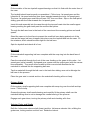
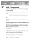
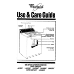
NEWAGE 85M2S GEARBOX
SERVICE MANUAL
WINGET LIMITED
PO BOX 41
EDGEFOLD INDUSTRIAL ESTATE
PLODDER LANE
BOLTON
LANCS BL4 OLS
U.K.
Tel:++44(0)1204 854650
Fax:++44(0)1204 854663
E-mail [email protected]
www.winget.co.uk
Introduction
Winget Limited gratefully acknowledge the assistance given by Newage Transmissions
Limited in the preparation of this manual, however neither Winget Limited or Newage
Transmissions can be held responsible for any errors or ommissions.
The procedures described within this manual should enable experienced service
personel to strip, repair and re-build Newage 85M2S Gearboxes fitted to Winget 4B and
4S range site dumpers in a safe and competant manner. The procedures are not
intended to be used by personnel who are unfamiliar with the product or mechanically
inexperienced.
It is assumed that personnel are aware of the Health and Safety Regulations which
should be applied but the following should act as a reminder.
Whenever possible any repairs or service should be carried out in a clean environment.
If work must be carried out on site or in the field steps should be taken to ensure that dirt
or foreign materials cannot enter the assembly.
Ensure all work tools are in good condition and only use the correct tool for the job in
hand.
Always wear safety spectacles when using soft or hard faced hammers, chisels, drifts or
when using air tools. Wear safety spectacles when cleaning components or when
grinding.
Do not misuse air lines and be aware of the damage compressed air can cause if
misused.
Always make sure lifting equipment is in good condition and the Safe Working Load
exceeds the weight of the component to be lifted.
Always use suitable supports i.e. axle stands or baulks of timber in conjuction with
hydraulic jacks etc. Never rely on hydraulic jacks alone to support a machine.
Be aware of hot surface temperatures and take care when draining hot oils. Always
dispose of waste oils in accordance with local and national regulations.
Whenever possible always disconnect the battery or battery isolator when working on the
machine to prevent electrical shorts and unauthorised starting.
Refer to the operators handbook for a guide to the correct sequence for assembling
components and sub-assemblies.
Oils, fuels, silicone sealer etc can cause skin diseases if allowed to contaminate the skin.
Always apply barrier creams, wear suitable protective clothing or when contamination is
unavoidable clean the area with soap and water as soon as possible. Do not use thinners
or other solvents to clean skin.
Health and Safety is a matter of common sense. If common sense is applied correctly
the risk of accidents can be reduced.
Spares for Newage Gearboxes fitted to Winget Equipment can only be obtained from
Winget Limited or one of our authorised distributors and not from Newage Transmissions
Limited. Always quote your machines serial number and model together with axle serial
number and model when ordering spare parts.
85M2S Gearboxes are designed to operate under arduous conditions and providing they
are regularly and correctly maintained they will provide long trouble free service.
Whilst every effort is made to ensure the contents of this manual are accurate Winget
Limited and Newage Transmissions reserve the right to alter specification without prior
notification and certain sections of this manual may then no longer apply.
GEARBOX 85M2S
Description
The gearbox provides three forward and one reverse gear.
The gearcase is constructed of heavy duty cast iron for rigidity and strength and the
shafts are hardened nickel steel supported by ball and roller bearings.
The gear train is of the constant mesh type and shifting is achieved by substantial
involute dogs of gear tooth form activated by a robust selector mechanism.
The design of the gear train is such that it will accept maximum torque in low gears for
long periods.
The weight of the basic 85M2S is approximately 34KG.
General
When overhauling the gearbox cleanliness is important, remove all dirt, cement etc from
the outside of the box before any inner parts are exposed. Take care with the dust within
the clutch/bell housing as it may contain minute particles of asbestos fibre which should
not be blown out with an airline. Damp the dust down and wipe out using damp cloths.
Dispose of the cloths safely after use.
Use a mandrel press, if available, for pressing out bearings, shafts etc. otherwise use
hardwood or non-ferrous metal drifts.
Work on a clean suface and wash all parts in clean solvent, lightly oiling before
reassembly. If new ball races are to be fitted do not unpack until they are required.
Drain the oil before stripping the gearbox.
Servicing and Disassembly
Remove the bolt through the clutch operating lever and remove the lever from the crossshaft. Undo and remove the cotter through the clutch fork, release the cross-shaft, circlip
and remove the cross-shaft, fork, circlip and washer.
Undo the six M6 setscrews retaining the oil seal housing/cover within the clutch/bell
housing and remove the cover, retrieve the six small nylon washers and gasket.
Undo the six M10 setscrews and the two M6 setscrews inside the clutch/bell housing and
remove the housing. The upper two M10 setscrews are fitted with nylon sealing washers
not spring washers.
Remove the hexagon headed dipstick, undo the six M6 setscrews securing the top cover
and remove the cover complete with gearlever.
The detent spacer, spring and ball for the 2nd/3rd speed selector shaft is retained into the
casing by the top cover and these should be removed, it may be necessary to use a
magnet to retrieve the detent ball.
Using the special tool spread the spring loaded safety interlock and remove from the
interlock plate.
If the special tool is not available insert the jaws of an open end spanner which is slightly
wider than the interlock plate between the safety interlock to prevent it snapping shut and
lift out, leave the spanner between the interlock until reassembly.
Untab the bolt through the output flange, prevent the flange from turning and slacken the
bolt. Remove the bolt, tabwashers, large retaining washer and pull off the flange. The
splines of the flange are sealed with silicone sealer which should be cleaned off.
Undo the six M10 setscrews and remove the rear cover, the cover is located on dowels
and care should be taken when removing.
Remove the short spacer off the end of the mainshaft.
Remove the grubscrew securing the 2nd/3rd speed selector fork to the shaft, slide out the
shaft and remove the fork. The grubscrew is peened over and incorporates a nylon
locking insert within the threads and can be exceptionally tight when removing. It is
recommended that this grub screw should be discarded after removal and a new screw
fitted on reassembly.
Remove the split pins through the two clevis pins, pull out the pins and lift out the
interlock plate.
The rear clevis is a sliding fit in the case and can be pulled free, the front clevis is
screwed into the case and should not be removed unless it is damaged or a new case is
being fitted.
Untab the locknut and remove the locknut and grubscrew securing the 1st/Reverse
selector fork to the 1st/Reverse selector shaft. Undo the grubscrew located on the side
of the casing adjacent to the selector shaft and remove the detent spring and ball. Slide
out the shaft and lift out the fork.
As the shaft is slid out of the bore on the rear of the box it will allow the three small detent
balls to drop out of the cross drilling in the case between the two selector shafts these
balls should be retrieved to prevent their loss.
Removal of Gear Set
Remove the primary shaft assembly, it may be necessary to lever between the mainshaft
and primary shaft or to tap out the primary shaft using a soft drift. Take care not to
damage the gear teeth in the process. Withdraw the needle bearing assembly located in
the end of the primary shaft. Remove the circlip and press the ball race complete with
snap ring off the primary shaft.
Align the teeth on the front of the mainshaft so they will pass between the teeth on the 1st
speed gear carried by the layshaft and tap the mainshaft out of the box.
The gears and spacers are removed from the back end of the mainshaft, one by one,
after it has cleared its supporting ball race in the back of the case. From inside the case
tap out the ball race complete with snap ring.
Remove the two small ball race retaining blocks retaining the larger of the two layshaft
ball races.
Align the teeth on the layshaft so they will pass the teeth on the reverse pinion and tap
the layshaft out of the small ball race until the rear larger ball race is clear of the case.
Place two plates approximately 3mm thick between the ball race and case and tap the
layshaft back into the gearbox, thus removing the ball race. Alternatively use a suitable
bearing puller.
Remove the small spacer and reverse layshaft gear via the ball race bore in the case, the
layshaft and remaining gears can be withdrawn through the opening in the top of the
case. Remove the bearing. The 1st speed gear on the layshaft is a tight fit, remove the
1st speed gear, reverse gear and the 2nd speed sliding gear. The layshaft is now
disassembled.
Undo the nuts on the reverse idler shaft and remove the retaining washer, gear, thrust
washer and needle bearing.
Undo the four small setscrews and from inside the case carefully tap out the idler shaft.
Check the needle bearing inner race located on the idler shaft.
Reassembly Details
Clean all parts incuding the interior of gearbox case thoroughly, examine all parts for
wear or damage. If the gearbox has been used on continuous heavy duty it is advisable
to replace all ball races, needle bearings and oil seals as a matter of course.
New oil seals should be fitted by pressing them in with a flat steel plate which covers their
entire area, otherwise they may buckle and be spoiled.
Output flanges frequently show signs of heavy wear where the oil seal has contacted
them. When this condition is observed the flange should be replaced.
Splines on the primary shafts which engage with the clutch friction discs are susceptable
to wear and distorton, check the splines with a new friction disc, if movement within the
splines is excessive or the friction disc will not slide freely on the splines the shaft should
be replaced.
The shafts and gears are treated with a phosphating process to ensure satisfactory
performance. Do not attempt to remove any apparent discolouration by polishing bearing
surfaces on shafts or in the bores of gears as seizure may result from the exposure of
unprotected steel surfaces.
Coat all threads on setscrews etc with threadlock on assembly.
Reassembly of Main Gearbox
Reverse Idler
Tap the reverse idler shaft into the case and refit the four small setscrews and spring
washers. Locate the thrustwasher, gear and needle bearing onto the shaft. Fit the
retaining washer onto the shaft with the flat uppermost. Secure the locknuts.
Layshaft
Fit the smaller of the two layshaft support bearings so that it is flush with the outer face of
the case.
The layshaft should now be partly re-assembled. Fit the inner 1st speed gear and the
inference fit 1st speed reducton gear (boss inwards towards the inner 1st speed gear).
The inner 1st speed gear must have at least .007" thou end float. Slip on the 2nd speed
sliding gear with the collar towards the 1st speed gears.
Insert this sub assembly into the case through the top and locate into the small support
bearing working the gear teeth past the reverse idler pinion.
Through the ball race bore in the back of the case insert the reversing pinion and small
spacer.
Stand the case on its front face to prevent the small ball race being pushed out of the
case as the larger ball race is tapped into place over the layshaft and into the case. Fit
the retainers, which should be down tight on the ball race.
Spin the layshaft and check all is free.
Mainshaft
Fit the mainshaft supporting ball race complete with the snap ring into the back face of
the case.
Pass the mainshaft through the front of the case feeding on the gears in this order:- 1st
speed gear (collar inwards), 2nd speed gear, spacer and the output gear (with the narrow
boss outwards). They must all be located on their correct shaft diameter as the
mainshaft is entered into the supporting ball race.
Tap the mainshaft through the ball race in the back face taking care not to dislodge the
ball race in the process.
Place the gear sets in neutral and turn the mainshaft checking all turns freely.
Primary Shaft
Fit the primary shaft supporting ball race complete with snap ring over the shaft and tap
home. Fit the circlip.
Grease the primary shaft needle bearing and carefully fit the primary shaft over the
mainshaft taking care to not to damage the needle bearing in the process.
Engage each gear inturn, turning the primary shaft and checking all is free.
Selector Forks and Shafts
Refit the 1st/reverse selector shaft (lower) and the 1st/reverse selector fork, refitting the
grubscrew, locking washer and lock nut. Retab the locknut.
Replace the three small detent balls into the cross drilling between the selector shafts.
Slide the lower shaft forward so the balls are below the level of the bore for the upper
shaft.
Clean up the “peened” threads in the 2nd/3rd speed selector fork, if the old one is to be
reused, using an M8 tap. Refit the 2nd/3rd speed selector fork secure to the shaft using
a new special grubscrew.
Detents and Interlock Plate
Ensure the gearsets are in neutral and refit the 1st/reverse detent ball and spring into the
side of the gearbox. Coat the threads of the grubscrew with threadlock and screw into
the case until flush. Check the 1st/reverse gear engage correctly, peen the grubscrew
and case as a secondary measure to prevent the grubscrew unscrewing.
Drop the 2nd/3rd detent ball and spring into the bore above the 2nd/3rd speed selector
shaft and fit the short spacer.
Using one of the clevis pins and a new split pin, assemble the rear clevis onto the
interlock plate.
Maintaining the gearsets in neutral, locate the assembly into the gearbox between the
selector forks, using the second clevis secure the interlock plate to the front clevis.
Before fitting the split pin ensure that the slots in the interlock plate and forks are aligned,
if not adjust the position of the interlock plate by screwing the front clevis in or out of the
case. Fit the split pin.
Locate the spring loaded safety interlock over the interlock plate and slide off the special
tool or spanner jaws.
Rear Cover
Coat the gasket surfaces with a suitable jointing compound, place the gasket over the
dowels locate the spacer over the mainshaft. Fit the rear cover, lubricating the oil seal
with grease, tap the rear cover over the dowels and tighten the six M8 setscrews.
Push the output flange fully onto the mainshaft, run a bead of silicone sealer in to the
flange sealing the end of the splines, fit and tighten the retaining washer, lockwasher and
bolt. Retab the bolt.
Top Cover and Gear Lever
Remove the gearlever knob and locknut, untab the steel cover and remove both the steel
and rubber covers from the gearlever.
Pull the gearlever out from underneath the top cover, remove both pads from the top
cover. Pull the retaining plate and spring off the end of the gearlever. Inspect the parts
and replace any worn parts.
Refit the two pads, push the gearlever back up into the top cover. Refit the rubber and
steel protective covers and retab the steel cover, refit the locknut and gear lever knob.
Slip the spring over the gearlever and fit the retaining plate.
Coat the gasket surfaces with a suitable jointing compound and lay the gasket in place.
Refit the top cover assembly ensuring the gear lever engages through the safety interlock
into the selector forks, secure the top in place with the six M6 setscrews.
Check that each gear is easily obtained.
Clutch/Bell Housing
Press two new bushes into the housing, coat the mating surface of the housing and
gearbox with a suitable jointing compound and secure the housing onto the gearbox
uising the six M10 and two M8 setscrews. Fit new nylon sealing washers to the two
upper M10 setscrews.
Coat the mating surfaces of the clutch/bell housing and seal housing with a suitable
jointing compound, lay the gasket in place, lubricate the oil seal with grease and secure
the seal housing into place using the six M6 setscrews, fit new nylon sealing washers.
With the clutch/bell housing facing you pass the cross-shaft into the housing from the R/H
side splines first. Push the cross-shaft through the clutch fork then fit the circlip into the
grove cut into the shaft, slip the flat washer onto the shaft upto the circlip. Pass the shaft
through the second bush. Fit the cotter pin, nut and washer. Fit the clutch operating
lever to the cross-shaft.
Top up the oil and refit the dipstick.
Tightenting Torques
1/4 UNF Threads
10lbft
13.5NM
M6 Threads
9lbft
12.2NM
M8 Threads
22lbft
29.8NM
M10 Threads
43lbft
58.3NM
Output flange bolt
40lbft
54NM
GEARBOX 85M2S
GEARBOX, 85M
Description
Item No
Qty
GEARBOX, 85M2S, assembly
1
2
3
4
5
COVER, protective
COVER, rubber
SPRING
PLATE, retaining
BALL
1
1
1
1
3
6
7
8
9
BALL, detent
SPRING
SCREW, grub
SCREW, grub
2
2
1
1
11
12
13
14
15
WASHER, locking
NUT
SHAFT, selector, 1st & reverse
PIN, split
CLEVIS, interlock plate
1
1
1
2
1
16
17
19
20
PIN, clevis
PLATE, interlocking
CLEVIS, interlock plate
SHAFT, selector, 2nd & 3rd speeds
2
1
1
1
21
22
23
24
25
SEAL, bonded
SPACER
DIPSTICK
COVER, top
GASKET
2
1
1
1
1
26
27
28
29
30
WASHER, spring
SCREW, set
KNOB
NUT
LEVER, gear select
6
6
1
1
1
31
32
33
34
PAD, gear lever
CLIP, bearing retainer
SCREW
WASHER, flat
2
2
2
2
36
37
38
39
40
BEARING
GEAR, reverse
SPACER
GEAR, 2nd speed
SHAFT, lay
1
2
1
1
1
41
42
BEARING, needle roller
GEAR, 1st speed
1
1
44
45
46
47
48
GEARCAS
BEARING
SHAFT, input
SCREW, grub
BEARING, c/w snap ring
1
1
1
1
1
49
50
51
52
53
CIRCLIP
PLUG, oil drain
NIPPLE
BUSH
SHAFT, clutch
1
1
2
2
1
FOR PART NUMBERS REFER TO RELEVANT PARTS MICROFICHE OR OPERATORS HANDBOOK
GEARBOX 85M2S
GEARBOX, 85M
Description
Item No
Qty
GEARBOX, 85M2S, assembly
54
55
56
57
SEAL, oil
NUT
BOLT
LEVER, clutch
1
1
58
HOUSING, clutch
1
59
60
61
61A
62
WASHER, spring
SCREW
WASHER, spring
WASHER
SCREW, set
2
2
6
2
6
63
64
65
66
67
WASHER, nylon
SCREW, set
GASKET, front cover
COVER, front, assembly
WASHER
6
6
1
1
1
68
69
70
71
72
CIRCLIP
PIN, NUT & WASHER assembly
FORK, clutch
SCREW
WASHER, tab
1
1
1
1
1
73
74
75
76
77
SPACER
WASHER
FLANGE, output
SHIELD, dust
SEAL, oil
1
1
1
1
1
78
79
80
81
82
BOLT
GASKET
DOWEL
BEARING
SPACER
6
1
2
1
1
83
84
END COVER
MAINSHAFT
1
1
85
86
87
88
89
90
91
92
93
94
SCREW
SHAFT, idler
WASHER, thrust
RING, inner
BEARING, needle
PINION, reverse
WASHER, idler
NUT
NUT, locking
GEAR 1st speed
4
1
1
1
1
1
1
1
1
1
95
96
97
98
99
100
110
111
GEAR, output
SPACER
GEAR, 2nd speed
NEUTRAL, interlock
FORK, selector
FORK, selector
SCREW, set
WASHER, spring
FOR PART NUMBERS REFER TO RELEVANT PARTS MICROFICHE OR OPERATORS HANDBOOK
1
1
1
1
1
1
1
8/12
8/12
19
35
55
84
168
294
696
17
30
48
73
146
255
606
5/16
3/8
7/16
1/2
5/8
3/4
1"
515
217
124
62
40
26
829
349
200
100
65
41
23
11
7
14
NOM.
MIN.
953
402
230
115
75
47
26
13
MAX.
GRADE V
704
297
170
85
55
35
19
10
MIN.
1004
423
243
121
79
50
28
14
NOM.
1155
487
279
140
91
58
32
16
MAX.
GRADE X
NOM.
10
21
38
59
91
183
319
757
SIZE
1/4
5/16
3/8
7/16
1/2
5/8
3/4
1"
871
367
210
105
68
43
24
12
643
271
156
78
51
32
18
9
1036
437
250
125
81
52
28
14
1191
502
288
144
94
59
33
16
MAX.
NOM.
MAX.
MIN.
GRADE V
GRADE S
881
371
213
106
69
44
24
12
MIN.
1255
529
303
152
99
63
35
17
NOM.
1443
609
349
174
113
72
40
20
MAX.
GRADE X
IMPERIAL IN POUNDS-FEET (LBF-FT) COATED THREADS, ZINC & ZINC PASSIVATED
10
8
1/4
MAX.
NOM.
SIZE
GRADE S
IMPERIAL IN POUNDS-FEET (LBF-FT) PLAIN THREADS
1067
450
258
129
84
53
29
15
MIN.
853
360
206
103
67
43
23
12
MIN.
24
20
16
12
10
8
6
5
SIZE
24
20
16
12
10
8
6
5
SIZE
770
450
210
96
56
28
11
7
MAX.
570
340
160
72
40
20
8
5
MIN.
920
560
280
115
67
33
14
8
NOM.
1040
640
320
130
77
37
16
9
MAX.
GRADE 10.9
800
480
240
100
57
29
12
7
MIN.
1171
677
347
140
80
40
17
10
NOM.
1347
779
399
161
92
47
19
11
MAX.
GRADE 12.9
868
502
257
104
59
30
12
7
NOM.
998
577
296
119
68
34
14
8
MAX.
GRADE 8.8
737
426
219
88
50
25
10
6
MIN.
1220
706
362
146
84
42
17
10
NOM.
1403
811
416
168
96
48
20
12
MAX.
GRADE 10.9
1037
600
307
124
71
36
15
9
MIN.
1464
847
434
175
100
51
21
12
NOM.
1684
974
499
201
115
58
24
14
MAX.
GRADE 12.9
METRIC IN NEWTON/METRES (Nm) COATED THREADS, ZINC & ZINC PASSIVATED
694
401
206
83
48
24
10
6
NOM.
GRADE 8.8
METRIC IN NEWTON/METRES (Nm) PLAIN THREADS
NEWAGE TRANSMISSIONS: TORQUE VALUES FOR FASTENERS WITH CLEAN & DRY THREADS
1244
720
369
149
85
43
18
10
MIN.
995
576
295
119
68
34
14
8
MIN.