1
MP540 / MP545
SIMPLIFIED SERVICE MANUAL
1.
2.
3.
LIST OF ERROR DISPLAY
ADJUSTMENT / SETTINGS
EXTERNAL VIEW / PARTS LIST
QY8-13CA-000
Rev.00
July 31, 2008
Canon Inc.
(1/58)
1.
LIST OF ERROR DISPLAY
Errors and warnings are displayed by the following ways:
- Operator call errors are indicated by the Alarm LED lit in orange, and the error and its solution
are displayed on the LCD in text and by icon.
- Messages during printing from a computer are displayed on the MP driver Status Monitor.
- Error codes (the latest 10 error codes at the maximum) are printed in the "operator call/service
call error record" area in EEPROM information print.
Buttons valid when an operator call error occurs:
- ON button: To turn the machine off and on again.
- OK button: To clear and recover from an error. In some operator call errors, the error will
automatically be cleared when the cause of the error is eliminated, and pressing
the OK button may not be necessary.
- Stop button: To cancel the job at error occurrence, and to clear the error.
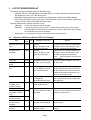
1-1. Operator Call Errors (Alarm LED Lit In Orange)
Error
No paper in the rear
tray.
No paper in the
cassette.
Error
U No.
code
Message on the LCD
[1000] --- Rear tray.
There is no paper. Load
paper and press [OK].
[1003] --- Cassette.
There is no paper. Load
paper and press [OK].
Paper jam.
[1300] --- The paper is jammed. Clear
Paper jam in the rear [1303] --- the paper and press [OK].
guide.
Ink may have run
[1600] U041 The following ink may have
out.
run out. Replacing the ink
tank is recommended.
Solution
Confirm that the rear tray is selected as
the paper source. Set the paper in the
rear tray, and press the OK button.
Confirm that the cassette is selected as
the paper source. Set the paper in the
cassette, and press the OK button.
Note:
Only plain paper can feed from
the cassette.
Remove the jammed paper, and press
the OK button.
Replace the applicable ink tank, or press
the OK button to clear the error without
ink tank replacement. When the error is
cleared by pressing the OK button, ink
may run out during printing.
Ink tank not installed. [1660] U043 The following ink tank cannot Install the applicable ink tank(s) properly,
be recognized.
and confirm that the LED's of all the ink
(Applicable ink tank icon)
tanks light red.
Print head not
Install the print head properly.
[1401] U051 Print head is not installed.
installed, or not
Install the print head.
properly installed.
Faulty print head ID.
U052 The type of print head is
Re-set the print head. If the error is not
incorrect. Install the correct cleared, the print head may be defective.
Print head
[1403]
print head.
Replace the print head.
temperature sensor
error.
Faulty EEPROM data [1405]
of the print head.
Multiple ink tanks of [1681] U071 More than one ink tank of the Replace the wrong ink tank(s) with the
the same color
following color is installed.
correct one(s).
installed.
Ink tank in a wrong
[1680] U072 Some ink tanks are not
Install the ink tank(s) in the correct
position.
installed in place.
position.
(2/58)
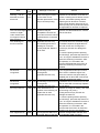
Error
Warning: The ink
absorber becomes
almost full.
Error
U No.
code
Message on the LCD
[1700, --- Contact the support center or
1701]
service center for ink
absorber replacement. Press
[OK] to continue printing.
The connected digital [2001] --- The device may be
camera or digital
incompatible. Remove the
video camera does
device and check the manual
not support Camera
supplied with the connected
Direct Printing.
device.
The remaining ink
[1683] U130 (Applicable ink tank icon)
amount unknown.
The remaining level of the
following ink cannot be
correctly detected. Replace
the ink tank.
Ink tank not
recognized.
[1684] U140 The following ink tank cannot
be recognized.
(Applicable ink tank icon)
Ink tank not
recognized.
[1410 U150 The following ink tank cannot
to
be recognized.
1419]
(Applicable ink tank icon)
[1688] U163 Printer detected ink out
condition of the following ink.
Replace the ink tank.
(Applicable ink tank icon)
No ink (no raw ink).
Non-supported hub
[2002] --- An unsupported USB hub is
connected. Remove the hub.
(3/58)
Solution
Replace the ink absorber, and reset its
counter. Pressing the OK button will exit
the error, and enable printing without
replacing the ink absorber. However,
when the ink absorber becomes full, no
further printing can be performed unless
the applicable ink absorber is replaced.
Remove the cable between the camera
and the machine.
An ink tank which has once been empty
is installed. Replace the applicable ink
tank with a new one. Printing with a
once-empty ink tank can damage the
machine.
To continue printing without replacing
the ink tank(s), press the Stop button for
5 sec. or longer to disable the function to
detect the remaining ink amount. After
the operation, it is recorded in the
machine EEPROM that the function to
detect the remaining ink amount was
disabled.
A non-supported ink tank (an ink tank
that is sold in a different region from
where the machine was purchased) is
installed (the ink tank LED is turned off).
Install the supported ink tanks.
A hardware error occurred in an ink tank
(the ink tank LED is turned off). Replace
the ink tank(s).
Replace the empty ink tank(s), and close
the scanning unit (cover).
Printing with an empty ink tank can
damage the machine.
To continue printing without replacing
the ink tank(s), press the Stop button for
5 sec. or longer to disable the function to
detect the remaining ink amount. After
the operation, it is recorded in the
machine that the function to detect the
remaining ink amount was disabled.
Remove the applicable USB hub from
the PictBridge (USB) connector.
Error
Time-out for the
scanner device
Error
U No.
code
Message on the LCD
[2700] --- Timeout error has occurred.
Press [OK].
Solution
The buffer became full in the middle of
scanning operation, and 60 minutes
have elapsed since then, making
re-scanning unstable. Press the OK
button to clear the error.
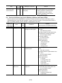
1-2. Service Call Errors (by Cyclic Blinking of Alarm and Power LEDs)
Service call errors are indicated by the number of cycles the Alarm and Power LEDs blink, and the
corresponding error code with the message, "Printer error has occurred. Turn off power then back on
again. If problem persists, see the manual." is displayed on the LCD.
Cycles of
Error
Solution
blinking of
Error
Conditions
code
(Check points and replacement items)
Alarm and
Power LEDs
2 times
Carriage error
[5100] An error occurred in the
1) Smearing or scratches on the carriage
carriage encoder signal.
slit film;
clean the timing slit film.
2) Foreign material or paper debris that
obstructs the carriage movement;
remove foreign material.
3) Ink tank conditions;
re-set the ink tanks.
4) Cable connection
5) Part replacement:
- Timing slit disk film
- Carriage unit
- Logic board
- Carriage motor
3 times
Line feed error [6000] An error occurred in the LF 1) Smearing or scratches on the LF slit
encoder signal.
film;
clean the LF slit film.
2) Foreign material or paper debris in the
LF drive;
remove foreign material.
3) Cable connection
4) Part replacement:
- LF slit film
- LF timing sensor unit
- Paper feed roller unit
- Logic board
- Paper feed motor
4 times
Purge cam
[5C00] An error occurred in the
1) Foreign material or paper debris
sensor error
purge unit.
around the purge drive system unit;
remove foreign material.
2) Cable connection
3) Part replacement:
- Purge drive system unit
- Logic board
(4/58)
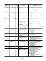
Cycles of
blinking of
Alarm and
Power LEDs
5 times
6 times
7 times
8 times
9 times
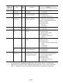
10 times
11 times
12 times
14 times
Error
ASF (cam)
sensor error
Error
code
[5700]
Conditions
An error occurred in the
ASF cam sensor.
Solution
(Check points and replacement items)
1) Cable connection
2) Part replacement:
- ASF unit
- PE sensor board unit
- Logic board
Internal
[5400] The internal temperature is 1) Cable connection
temperature
not normal.
2) Part replacement:
error
- Carriage unit
- Logic board
- Print head
1) Ink absorber condition
Ink absorber full [5B00] The ink absorber is
2) Part replacement:
[5B01] supposed to be full.
- Ink absorber kit
Message on the LCD:
Ink absorber full. Service 3) Ink absorber counter value in the
EEPROM;
required.
reset the ink absorber counter.
Error codes:
5B00: Main ink absorber
is full (non-Japan).
5B01: Main ink absorber
is full (Japan).
Print head
[5200] The print head temperature 1) Print head condition
temperature rise
exceeded the specified
2) Cable connection
error
value.
3) Part replacement:
- Print head
- Logic board
EEPROM error [6800] A problem occurred in
1) Part replacement:
[6801] reading from or writing to
- Logic board
the EEPROM.
VH monitor error [B200] The internal temperature
1) Part replacement:
exceeded the specified
- Print head and logic board
value.
(Replace them at the same time.)
- Power supply unit
Carriage lift
[5110] The carriage did not move 1) Foreign material or paper debris that
mechanism
up or down properly.
obstructs the carriage movement;
error
remove foreign material.
2) Part replacement:
- Switch system unit
- Carriage unit
APP position
[6A80] An error occurred in the
1) Foreign material or paper debris
error
APP motor.
around the purge drive system unit;
remove foreign material.
APP sensor
[6A90] An error occurred during
2) Foreign material or paper debris
error
paper feeding or purging.
around the ASF unit;
remove foreign material.
3) Cable connection
4) Part replacement:
- Purge drive system unit
- Logic board
(5/58)
Cycles of
blinking of
Alarm and
Power LEDs
15 times
16 times
19 times
20 times
21 times
22 times
23 times
Note:
Error
Error
code
USB Host VBUS [9000]
overcurrent
Pump roller
[5C20]
sensor error
Conditions
The USB Host VBUS is
overloaded.
The pump roller position
cannot be detected.
Solution
(Check points and replacement items)
1) Part replacement:
- Logic board
1) Cable connection
2) Part replacement:
- Purge drive system unit
Ink tank position [6502] None of the ink tank
1) Ink tank position;
sensor error
position is detected.
confirm the ink tank position.
2) Re-set or replacement of ink tanks
3) Cable connection
4) Part replacement:
- Spur unit
- Logic board
Other errors
[6500] An unidentified error
1) Part replacement:
occurred.
- Logic board
Drive switch
[C000] Drive was not switched
1) Foreign material or paper debris in the
error
properly.
drive switch area;
remove foreign material.
2) Part replacement:
- Purge drive system unit
- ASF unit
Scanner error
[5011] An error occurred in the
1) Document pressure sheet conditions
scanner.
2) Cable connection
3) Part replacement:
- Document pressure sheet (sponge
sheet)
- Scanner unit
- Logic board
Flatbed motor
[5012] An error occurred in the
1) Cable connection
error
scanner flatbed motor.
2) Part replacement
- Scanner unit
Valve cam
[6C10] The valve cam sensor was 1) Foreign material or paper debris
sensor error
faulty at power-on or when
around the purge drive system unit;
purging was attempted.
remove foreign material.
2) Cable connection
3) Part replacement:
- Purge drive system unit
- Logic board
Before replacement of the logic board ass'y, check the ink absorber counter value (by
service test print or EEPROM information print). If the counter value is 7% or more, also
replace the ink absorber kit when replacing the logic board ass'y. If the counter value is less
than 7%, register the current ink absorber counter value to the replaced new logic board.
(6/58)
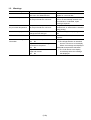
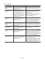
1-3. Warnings
Warning
Message on the LCD
Low ink
"!" is indicated for an applicable ink
tank icon in the Status Monitor.
Print head temperature rise If the print head temperature does not
fall, the print head error will occur.
Solution
Since the ink will be used up soon,
prepare for a new ink tank.
When the print head temperature falls,
the error is automatically cleared. If the
print head error is indicated, repair
servicing is required.
Protection of excess rise of If the print head temperature does not If the print head temperature exceeds the
the print head temperature fall, the print head error will occur.
specified limit, an intermission is inserted
during printing.
Restrictions on paper
The current paper cannot be set.
Re-select the supported paper type and
Change the size and type.
size.
USB cable not connected
Set the PC to start scan.
Connect the USB cable, then turn on the
computer.
Cancellation of image select Reset the selected photo information? - Select Yes, and press the OK button.
=> The image selection is cancelled,
information
Yes
No
and the LCD returns to the display
Do you want to clear the image
before the message was displayed.
scanned from the photo?
- Select No, and press the OK button.
Yes
No
=> The LCD returns to the display
Do you want to clear the scanned
immediately before the message
image and rescan?
was displayed.
Yes
No
(7/58)
2.
ADJUSTMENT / SETTINGS
2-1. Service Mode
< Service mode operation procedures >
Use the Service Tool on the connected computer.
1) Start the machine in the service mode.
i.
With the machine power turned off, while pressing the Stop button, press and hold the ON
button. (DO NOT release the buttons).
ii. When the Power LED lights in green, while holding the ON button, release the Stop button.
(DO NOT release the ON button.)
iii. While holding the ON button, press the Stop button 2 times, and then release both the ON
and Stop buttons. (Each time the Stop button is pressed, the Alarm and Power LEDs light
alternately, Alarm in orange and Power in green, starting with Alarm LED.)
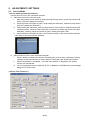
iv. When the Power LED lights in green, the machine is ready for the service mode operation.
- LCD ready for the service mode operation:
2)
Start the Service Tool on the connected computer.
i.
When a button is clicked in the Service Tool dialog box, that function is performed. During
operation of the selected function, all the Service Tool buttons are dimmed and inactive.
ii
When the operation is completed, "A function was finished." is displayed, and another
function can be selected.
iii If a non-supported function is selected, "Error!" is displayed. Click OK in the error message
dialog box to exit the error.
< Service Tool Functions >
(8/58)
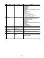
No.
Name
Function
Remarks
(1)
Test Print
Service test print
Paper will feed from the rear tray.
Service test print:
- Model name
- ROM version
- Ink absorber counter value (ink amount in the ink
absorber)
- USB serial number
- Destination
- EEPROM information
- Process inspection information
- Barcode (model name + destination)
- Ink system function check result
(2)
EEPROM
EEPROM information print The dialog box opens to select the paper source.
Select Rear tray or Cassette, and click OK.
EEPROM information print:
- Model name
- ROM version
- Ink absorber counter value (ink amount in the ink
absorber)
- Print information
- Error information, etc.
(3)
CD-R
CD-R check pattern print
Not used.
(4)
LF / Eject
LF / Eject correction
pattern print
See “LF / Eject correction” below.
(5)
Left Margin
Left margin pattern print
Not used.
(6)
Deep Cleaning
Print head deep cleaning
Cleaning of both Black and Color at the same
time.
(7)
Main
Main ink absorber counter Set a sheet of A4 or Letter sized plain paper. After
resetting
the ink absorber counter is reset, the counter value
is printed automatically.
(8)
Platen
Platen ink absorber
counter resetting
Not used.
(9/58)
No.
(9)
Name
EEPROM Clear
Function
Remarks
EEPROM initialization
The following items are NOT initialized, and the
shipment arrival flag is not on:
- USB serial number
- Destination settings
- Record of ink absorber counter resetting and
setting
- Record of repair at the production site
- LF / Eject correction values
- Left margin correction value
- Production site E-MIP correction value and
enabling of it
- Endurance correction value and enabling of it
- Record of disabling the function to detect the
remaining ink amount
- Ink absorber counter value (ink amount in the ink
absorber)
(10) Panel Check
Button and LCD test
See "Button and LCD test" below.
(11) Set Destination
Destination settings
Select the destination, and click OK.
ASA, AUS, BRA, CHN, CND, EUR, JPN, KOR,
LTN, TWN, USA
(12) CD-R Correction
CD / DVD print position
correction (X and Y
direction)
Not used.
(13) LF / EJECT
Correction
LF / Eject correction value See " LF / Eject correction " below.
setting
(14) Left Margin Correction Left margin correction
value setting
Not used.
(15) Ink Absorber Counter Ink absorber counter
setting
See " Ink absorber counter setting " below.
< LF / Eject correction >
After replacement of the feed roller, platen unit, LF / Eject encoder, encoder film, or logic board in
repair servicing or in refurbishment operation, perform the adjustment to maintain the optimal print
image quality.
1) Print the LF / Eject correction pattern.
Click LF/EJECT of the Service Tool on the connected computer, select the paper source and the
paper type, and print the pattern. 5 sheets of paper will be used for the pattern printing.
- Paper source: Select either Rear tray or Cassette.
- Media type:
Select one from HR-101, GF-500/Office Planner, HP Bright White, and
Canon Extra/STEINBEIS.
2) When printing is finished, the machine returns to be ready for selection of another function
("Service Mode Idle" is displayed on the LCD).
3) In the printout, determine the Pattern No. in which streaks or lines are the least noticeable for the
LF check pattern and the Eject check pattern respectively. (LF Pattern No. 0 to 4, Eject Pattern
No. 0 to 4)
(10/58)
(11/58)
4) In the LF/EJECT Correction section of the Service Tool, select the Pattern No. (from 0 to 4)
determined in step 3) for LF and EJECT respectively, and click Set.
5) The selected LF and Eject correction values are written to the EEPROM, making the E-MIP
correction value (which was set at shipment from the production site) invalid.
Note: At the production site, the E-MIP correction, which is equivalent to the LF / Eject correction,
is performed using the special tool, and the E-MIP correction value is written to the EEPROM
as the valid data.
When LF / Eject correction is performed, the LF / Eject correction values become valid
instead of the E-MIP correction value (thus, in the initial EEPROM information print, "LF = *"
and "EJ = *" are printed, but the selected values are printed after the LF / Eject correction).
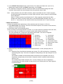
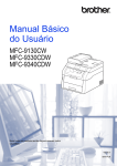
< Button and LCD test >
Confirm the operation after replacement of the operation panel unit, board, or LCD unit.
1) Click Panel Check of the Service Tool on the connected computer. The machine LCD turns blue,
waiting for a button to be pressed.
2) Press each button of the operation panel.
3) Only one button should be pressed at one time. If 2 or more buttons are pressed at the same time,
only one of them is considered to be pressed, and the other buttons are ignored.
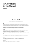
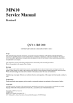
The LCD is divided into 16 segments, representing each button. The color of a segment
corresponding to the pressed button changes to red.
1: ON button
9: Color button
2: Back button
10: Stop button
3: OK button
11: NAVI button
4: Up cursor button
12: HOME button
5: Down cursor button 13: Left function button
6: Left cursor button
14: Right function button
7: Right cursor button 15: [+] button
8: Black button
16: [-] button
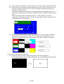
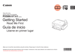
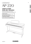
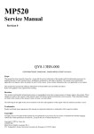
4) Rotate the Easy-Scroll Wheel clockwise and counterclockwise 1 round (16 steps) each, as
follows:
4-1) Rotate the Easy-Scroll Wheel clockwise step by step. The LCD is divided into 16 segments,
representing each step. The color of a segment corresponding to the step changes from red
to green.
If the wheel is rotated counterclockwise before clockwise round completes, the color of
segment(s) corresponding to the number of steps the wheel is rotated counterclockwise
returns to red.
If the wheel keeps rotated clockwise over 1 round (16 steps), the color of segment(s)
corresponding to the extra number of steps returns to red, starting with the "Start" segment
in the figure below.
(12/58)
4-2) When the Easy-Scroll Wheel is rotated clockwise 1 round (16 steps), press the OK button.
4-3) Rotate the Easy-Scroll Wheel counterclockwise step by step. The LCD is divided into 16
segments, representing each step. The color of a segment corresponding to the step
changes from green to blue.
If the wheel is rotated clockwise before counterclockwise round completes, the color of
segment(s) corresponding to the number of steps the wheel is rotated clockwise returns to
green.
If the wheel keeps rotated counterclockwise over 1 round (16 steps), the color of
segment(s) corresponding to the extra number of steps returns to green, starting with the
"Start" segment in the figure below.
4-4) When the Easy-Scroll Wheel is rotated counterclockwise 1 round (16 steps, and all the
segments are in blue), press the OK button. The color pattern is displayed on the LCD.
If there is any segment that is not in blue when the OK button is pressed, the display
remains unchanged.
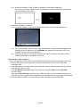
5) Adjust the transparent color, as follows:
5-1) Press the OK button. "OK1" in white is displayed on the black background.
If the result is not good, "NG1" in black is displayed on the white background (transparent
color) immediately after "OK1."
(13/58)
5-2) Press the OK button. "OK2" in black is displayed on the white background.
If the result is not good, "NG2" in white is displayed on the black background (transparent
color) immediately after "OK2."
6) Adjust the LCD flicker, as follows:
6-1) Press the OK button. The screen is displayed as below for LCD flicker adjustment.
6-2) If the screen flickers, press the left or right cursor button until the flickering disappears. By
pressing the left or right cursor, the VrefPWM value displayed at the bottom of the LCD
changes from 36 to 3D (in hexadecimal).
6-3) Press the OK button. The machine returns to be ready for selection of another function
("Service Mode Idle" is displayed on the LCD).
< Ink absorber counter setting >
Set the ink absorber counter value to a new EEPROM after the logic board is replaced in servicing.
1) Before replacement of the logic board, check the ink absorber counter value in EEPROM
information print.
2) After replacement of the logic board, the ink absorber counter value should be set in the service
mode using the Service Tool.
In the Ink Absorber Counter section of the Service Tool, select Main from the Absorber
pull-down menu.
From the Counter Value(%) pull-down menu, select the value (in 10% increments) which is the
closest to the actual counter value confirmed before replacement of the logic board, and click Set.
3) Print EEPROM information to confirm that the value is properly set to the EEPROM.
(14/58)
2-2. User Mode
Function
Procedures
Remarks
Nozzle check pattern
printing
Perform via the machine operation
panel, or from the MP driver
Maintenance tab.
Set a sheet of plain paper (A4 or Letter) in
the cassette, or the rear tray if selected.
Print head manual
cleaning
- Cleaning both Black and Color:
Perform via the machine
operation panel, or from the MP
driver Maintenance tab.
- Cleaning Black or Color separately:
Perform from the MP driver
Maintenance tab.
Unclogging of the print head nozzles, and
maintenance to keep the print head
conditions good.
If there is a missing portion or white streaks
in the nozzle check pattern printout,
perform this cleaning.
Print head deep
cleaning
Perform via the machine operation
panel, or from the MP driver
Maintenance tab.
If print head cleaning is not effective,
perform this cleaning. Since the deep
cleaning consumes more ink than regular
cleaning, it is recommended to perform
deep cleaning only when necessary.
Manual print head
alignment
Perform via the machine operation
panel, or from the MP driver
Maintenance tab.
Set 3 sheets of plain paper (A4 or Letter) in
the cassette, or the rear tray if selected.
Print head alignment
value printing
Perform via the machine operation
panel, or from the MP driver
Maintenance tab.
Confirmation of the current print head
alignment values.
Paper feed roller
cleaning
Perform via the machine operation
panel, or from the MP driver
Maintenance tab.
The paper feed rollers of the selected
paper source (the rear tray or the cassette)
rotate while being pushed to the paper
lifting plate. Since the rollers will wear out in
this cleaning, it is recommended that you
perform this only when necessary.
Bottom plate cleaning
Perform via the machine operation
panel, or from the MP driver
Maintenance tab.
Cleaning of the platen ribs when the back
side of paper gets smeared.
Fold a sheet of plain paper (A4 or Letter) in
half crosswise, then unfold and set it in the
rear tray with the folded ridge facing down.
(No paper feeding from the cassette)
(15/58)
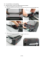
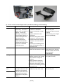
2-3. Special Notes on Assembling
(1)
External housing, scanner unit, and document cover removal
1) Remove the cassette, and open the front door.
2) Pull up the document cover to remove it, then remove the rear top cover and the middle frame
(4 screws).
3)
Remove the side cover R (2 screws).
< The scanner unit hinges are fitted in the right and left side covers. >
(16/58)
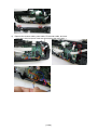
4)
Remove the scanner cable, panel cable, FB encoder cable, and core.
< The core is fixed on the rib of the sub-case (back of the main case). >
(17/58)
5)
Remove the side cover L and scanner unit (2 screws).
< While holding the scanner unit, separate the scanner stay from the side cover L. >
6)
Remove the operation panel unit (11 screws).
(18/58)
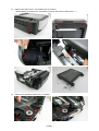
7)
Remove the main case and sub-case (1 screw).
(19/58)
(2)
Notes on Service Part Replacement (and Disassembling / Reassembling)
Service part
Notes on replacement*1
Adjustment / settings
Logic board ass'y - Before removal of the logic After replacement:
1) Initialize the EEPROM.
board ass'y, remove the
power cord, and allow for 2) Set the ink absorber counter
value.
approx. 1 minute (for
3) Set the destination in the
discharge of capacitor's
EEPROM.
accumulated charges), to
4) Check the ink system function.
prevent damages to the
5) Perform LF / Eject correction.
logic board ass'y.
6) Perform button and LCD test.
- Before replacement,
Perform 1 to 6 in the service
check the ink absorber
mode.
counter value (by service
7) Perform print head alignment
test print or EEPROM
and LCD language setting in
information print).
the user mode.
Absorber kit
After replacement:
1) Reset the ink absorber counter.
Carriage unit
Switch system
unit
- The red screws securing
the paper feed motor are
allowed to be loosened
Paper feed motor only for paper feed motor
replacement. (DO NOT
loosen them in any other
cases.)
Operation check
- EEPROM information print
- Service test print
- Printing via USB connection
- Copying
- Direct printing from a digital
camera (PictBridge)
- Ink absorber counter value
print (After the ink absorber
counter is reset, the counter
value is printed
automatically.)
- Service test print (Confirm
At replacement:
1) Before removal of the carriage ink system function.)
rail, mark the carriage rail
position.
2) Apply grease to the sliding
portions of the carriage rail.
3) Check the ink system function.
4) Perform print head alignment in
the user mode.
- EEPROM information print
At replacement:
1) Adjust the paper feed motor.
- Service test print
(20/58)
Service part
Notes on replacement*1
Adjustment / settings
Platen unit
After replacement:
1) Perform LF / Eject correction in
the service mode.
Spur unit
- DO NOT contact the spur After replacement:
edges.
1) Check the ink system function.
2) Perform LF / Eject correction in
the service mode.
After
replacement:
Purge drive
1) Confirm the purging operation
system unit
and the machine operation.
At
replacement:
Carriage rail and
1) Apply grease to the sliding
main chassis
portions.
Idler pulley
parallel pin
Easy-Scroll
Wheel base
APP code wheel
gear shaft
At replacement:
Document cover
1) Confirm the document pressure
unit
sheet position.
Scanner unit
At
replacement:
Panel board
- Be cautious not to scratch
ass'y
or damage the LCD cable. 1) Perform button and LCD test.
LCD unit
Timing slit strip
film
Operation check
- EEPROM information print
- Service test print
- EEPROM information print
- Service test print
- Service test print
- Service test print
- Service test print
- Service test print
- EEPROM information print
- Upon contact with the film, After replacement:
wipe the film with ethanol. 1) Perform print head alignment in - Service test print
the user mode.
- Confirm no grease is on
2) Perform LF / Eject correction in
the film. (Wipe off any
Timing slit disk
the service mode.
grease thoroughly with
feed film
ethanol.)
- Do not bend the film
Print head
- Service test print
After replacement:
1) Perform print head alignment in
the user mode.
*1: General notes:
- Make sure that the flexible cables and wires in the harness are in the proper position and
connected correctly.
- Do not drop the ferrite core, which may cause damage.
- Protect electrical parts from damage due to static electricity.
- Before removing a unit, after removing the power cord, allow the machine to sit for approx. 1
minute (for capacitor discharging to protect the logic board ass'y from damages).
- Do not touch the timing slit strip film, and timing slit disk feed film. No grease or abrasion is
allowed.
- Protect the units from soiled with ink.
- Protect the housing from scratches.
- Exercise caution with the screws, as follows:
i. The screws of the paper feed motor may be loosened only at replacement of the paper
feed motor unit (DO NOT loosen them in other cases).
ii. Before loosening the 3 screws that fix the carriage rail to the main chassis, mark the
screw positions so that the carriage rail will be re-attached to the main chassis in its
(21/58)
original position.
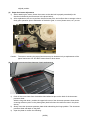
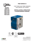
(3)
Paper feed motor adjustment
1) When attaching the motor, fasten the screws so that the belt is properly stretched (in the
direction indicated by the blue arrow in the photo below).
2) After replacement, be sure to perform the service test print, and confirm that no strange noise or
faulty print operation (due to dislocation of the belt or gear, or out-of-phase motor, etc.) occurs.
Caution: The screws securing the paper feed motor may be loosened only at replacement of the
paper feed motor unit. DO NOT loosen them in other cases.
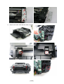
(4)
Document pressure sheet (sponge sheet) replacement
1)
2)
3)
Peel off the cover sheet from the double-sided adhesive tape on the back of the document
pressure sheet.
With the long-side down, position the upper-left corner of the document pressure sheet at the
scanning reference point on the platen glass (back left where the red lines cross in the photo
above).
Slowly close the document pressure plate while maintaining the hinge position. The document
pressure sheet will attach to the plate.
Open the plate to confirm the following:
(22/58)
- No extension of the sponge edges over the mold part of the upper scanner cover.
- No gap between the platen glass reference edges and the corresponding sponge edges.
- No shades or streaks in monochrome test printing without a document on the platen glass.
(5)
Ink absorber counter setting
Before replacement of the logic board, check the ink absorber counter value, and register it to the
replaced new logic board. (The value can be set in 10% increments.)
In addition, according to the ink absorber counter value, replace the ink absorber (ink absorber kit).
When the ink absorber is replaced, reset the applicable ink absorber counter (to 0%).
(23/58)
2-4. Grease application
(1)
Printer unit
No.
Part name
Where to apply grease / oil
*1
Grease
Grease
amount (mg)
*2
1 Carriage rail
The surface where the carriage unit slides
(1)
Floil KG107A
270 to 330
---
2 Carriage rail
The surface where the carriage unit slides
(2)
Floil KG107A
18 to 36
1x2
3 Carriage rail
The surface where the carriage unit slides
(3)
Floil KG107A
360 to 440
---
4 Carriage rail
The surface where the carriage unit slides
(4)
Floil KG107A
360 to 440
---
5 Main chassis
The surface where the carriage unit slides
(5)
Floil KG107A
230 to 290
---
6 Parallel pin
The pin surface which contacts the idler pulley
hole
(6)
Floil KG107A
9 to 18
1x1
(7)
Floil KG107A
9 to 18
1x1
7 APP code wheel APP code wheel gear sliding portion (the entire
gear shaft
surface)
*1: Drawing No.
*2: Number of drops (1 drop = 9 to 18 mg) x locations
(24/58)
(2)
Operation panel, Easy-Scroll Wheel
No.
Part name
Where to apply grease / oil
8 Easy-Scroll Wheel base Easy-Scroll Wheel sliding portions
(25/58)
Drawing
No.
(8)
Grease
Grease
amount (mg)
Floil KG107A
9 to 18
2-5. Notes on Transportation
This section describes the procedures for transporting the machine for returning after repair, etc.
1) In the service mode, press the ON button to finish the mode, and confirm that the paper lifting
plate of the rear tray is raised.
2) Keep the print head and ink tanks installed in the carriage. See Caution (a) below.
3) Turn off the machine to securely lock the carriage in the home position. (When the machine is
turned off, the carriage is automatically locked in place.) See Caution (b) below.
Caution:
a.
b.
Note:
If the print head is removed from the machine and left alone by itself, ink (the
pigment-based black ink in particular) is likely to dry. For this reason, keep the print
head installed in the machine even during transportation.
Securely lock the carriage in the home position, to prevent the carriage from moving
and applying stress to the carriage flexible cable, or causing ink leakage, during
transportation.
- If the print head must be removed from the machine and transported alone, attach the
protective cap (used when the packing was opened) to the print head (to protect the print
head face from damage due to shocks).
- If the packing material that fixed the carriage from the factory is still available, re-use it to fix
the carriage (to prevent the carriage unlocked during transportation).
(26/58)
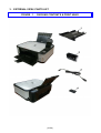
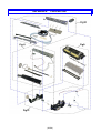
3.
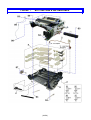
EXTERNAL VIEW / PARTS LIST
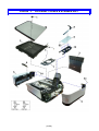
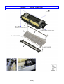
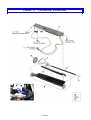
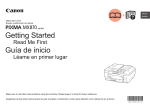
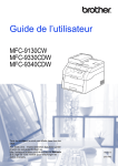
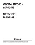
FIGURE 1
PACKING CONTENTS & PRINT HEAD
(27/58)
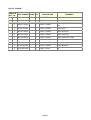
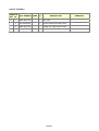
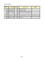
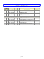
LIST OF FIGURE 1
FIGURE &
PART NUMBER RANK QTY
KEY No.
1-
DESCRIPTION
REMARKS
1
QM3-3685-000
1
CASSETTE UNIT
2
QY6-0073-000
1
PRINT HEAD
3
QH2-2716-000
1
CORD, POWER
220V-240V(EUM, EMB, ASA,
MY)
3
QH2-2719-000
1
CORD, POWER
100V-120V
3
QK1-0776-000
1
CORD, POWER
220V-240V(AU)
3
QK1-2017-000
1
CORD, POWER
100V-120V(TW)
3
QK1-3048-000
1
CORD, POWER
120V-240V(LAM, CHN)
3
QK1-3761-000
1
CORD, POWER
100V(JP)
3
WT3-5156-000
1
CORD, POWER
220V-240V(GB, HK)
3
WT3-5160-000
1
CORD, POWER
220V-240V(KR)
4
QC2-7932-000
1
LABEL, PANEL
CA
(28/58)
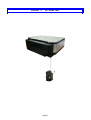
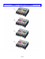
FIGURE 2
AC ADAPTER
(29/58)
LIST OF FIGURE 2
FIGURE &
PART NUMBER RANK QTY
KEY No.
2-
1
QK1-4965-000
1
DESCRIPTION
AC ADAPTER: 100V-240V 50/60HZ
(30/58)
REMARKS
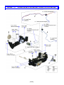
FIGURE 3
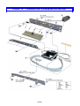
EXTERNAL COVERS & SCANNER UNIT
(31/58)
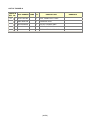
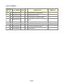
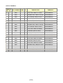
LIST OF FIGURE 3
FIGURE &
PART NUMBER RANK QTY
KEY No.
3-
DESCRIPTION
REMARKS
1
QC1-9023-000
1
EMBLEM
FOR JAPAN
1
QC1-9024-000
1
EMBLEM
FOR OTHER
REGIONS
2
QM3-3689-000
1
SCANNER UNIT
3
QM3-3684-000
1
ASF COVER UNIT
4
QM3-3682-000
1
SIDE COVER R UNIT
5
QM3-3683-000
1
SIDE COVER L UNIT
6
QC2-7841-000
1
STAY, SCANNER
7
QL2-2602-000
1
COVER, OPERATION PANEL
CA, AU, ASA
7
QL2-2603-000
1
COVER, OPERATION PANEL
JP
7
QL2-2604-000
1
COVER, OPERATION PANEL
LAM, GB, EUM,
EMB
7
QL2-2605-000
1
COVER, OPERATION PANEL
HK, TW
7
QL2-2606-000
1
COVER, OPERATION PANEL
CN
7
QL2-2607-000
1
COVER, OPERATION PANEL
KR
8
QC2-7872-000
1
EDGE PANEL, OPERATION
9
QC2-7871-000
1
TOP COVER, OPERATION REAR
10
QC2-7874-000
1
MIDDLE FRAME, OPERATION
REAR
(32/58)
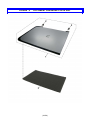
FIGURE 4
DOCUMENT PRESSURE PLATE UNIT
(33/58)
LIST OF FIGURE 4
FIGURE &
PART NUMBER RANK QTY
KEY No.
4-
DESCRIPTION
1
QM3-3692-000
1
DOCUMENT COVER UNIT
2
QC2-7863-000
2
HINGE
3
QC2-9324-000
1
SHEET, DOCUMENT
PRESSURE
(34/58)
REMARKS
FIGURE 5
OPERATION PANEL UNIT
(35/58)
LIST OF FIGURE 5
FIGURE &
PART NUMBER RANK QTY
KEY No.
5-
DESCRIPTION
REMARKS
1
QC2-7873-000
1
GUIDE, LIGHT
2
QC2-7870-000
1
FRAME, PANEL
3
QC2-7919-000
1
KEY, ARROW
4
QC2-7878-000
1
KEY, OK
5
QC2-7879-000
1
JOG WHEEL
6
QC2-7877-000
1
KEY, POWER
7
QC2-7876-000
1
KEY, START
8
QC2-8026-000
1
BASE, JOG WHEEL
9
QM3-3709-000
1
PANEL BOARD ASS'Y
10
QM3-3696-000
1
LCD UNIT
11
QC2-9308-000
1
LABEL, PRODUCT NAME
MP540
11
QC2-9309-000
1
LABEL, PRODUCT NAME
MP545
12
QC2-7885-000
1
WINDOW, LCD
13
QC2-7882-000
1
COVER, LCD FRONT
14
QC2-7886-000
1
HINGE, LCD L
15
QC2-7887-000
1
HINGE, LCD R
16
QL2-2609-000
1
LCD CABLE ASS'Y
17
QC2-7883-000
1
COVER, LCD TOP
18
QC2-7884-000
1
EDGE PANEL, LCD
(36/58)
FIGURE 6
MAIN CASE & FRONT DOOR UNIT
(37/58)
LIST OF FIGURE 6
FIGURE &
PART NUMBER RANK QTY
KEY No.
6-
DESCRIPTION
1
QM3-3641-000
1
REAR GUIDE UNIT
2
QC2-7844-000
1
CASE, MAIN
3
QM3-3681-000
1
FRONT DOOR UNIT
4
QM3-3694-000
1
SUB CASE UNIT
5
QC2-7925-000
1
SHEET, PE BIND
(38/58)
REMARKS
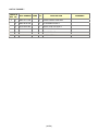
FIGURE 7
BOTTOM CASE & INK ABSORBER
(39/58)
LIST OF FIGURE 7
FIGURE &
PART NUMBER RANK QTY
KEY No.
7-
DESCRIPTION
1
QM3-3711-000
1
FRONT DOOR LINK UNIT
2
QM3-4278-000
1
DC HARNESS ASS'Y
3
QC2-7654-000
1
GEAR, PICK UP SHAFT
4
QM3-3644-000
1
PICK UP ARM UNIT
5
QY5-0239-000
1
ABSORBER KIT
6
QC2-7908-000
1
CASE, BOTTOM
(40/58)
REMARKS
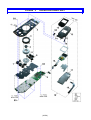
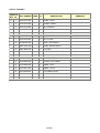
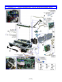
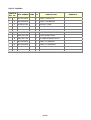
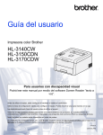
FIGURE 8
LOGIC BOARD ASS’Y & PE SENSOR BOARD ASS’Y
(41/58)
LIST OF FIGURE 8
FIGURE &
PART NUMBER RANK QTY
KEY No.
8-
DESCRIPTION
1
QK1-4512-000
1
CABLE, CARD SLOT
2
QK1-5002-000
1
CABLE, PICTBRIDGE
3
QC2-8523-000
1
HOLDER, CORE
4
QC2-7850-000
1
PANEL, CARD
5
QM3-3708-000
1
CARD BOARD ASS'Y
6
QM3-4467-000
1
PICTBRIDGE BOARD UNIT
7
QM3-3707-000
1
LOGIC BOARD ASS'Y
8
QM3-4451-000
1
PE SENSOR BOARD ASS'Y
9
QK1-4835-000
1
CABLE, PE SENSOR
10
QK1-5034-000
1
CABLE, LF ENCODER
11
QK1-4815-000
1
CABLE, PANEL
12
QC2-7921-000
1
FRONT COVER, MIDDLE
(42/58)
REMARKS
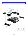
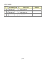
FIGURE 9
SHEET FEED UNIT
(43/58)
LIST OF FIGURE 9
FIGURE &
PART NUMBER RANK QTY
KEY No.
9-
DESCRIPTION
1
QM3-3633-000
1
ASF UNIT
2
QL2-2529-000
1
PAPER FEED ROLLER ASS'Y
3
QM3-3610-000
1
CASSETTE FEED GUID UNIT
4
QM3-4757-000
1
PAPER GUIDE UNIT
(44/58)
REMARKS
FIGURE 10
CARRIAGE UNIT & PRESSURE ROLLER UNIT
(45/58)
LIST OF FIGURE 10
FIGURE &
PART NUMBER RANK QTY
KEY No.
10-
DESCRIPTION
1
QC2-7783-000
1
FILM, TIMING SLIT STRIP
2
QM3-3598-000
1
CARRIAGE UNIT
3
QL2-2528-000
1
PULLEY HOLDER UNIT
4
QK1-1500-000
1
MOTOR, CARRIAGE
5
QM3-3614-000
1
PRESSURE ROLLER ASS'Y
(46/58)
REMARKS
FIGURE 11
PLATEN UNIT & SPUR UNIT
(47/58)
LIST OF FIGURE 11
FIGURE &
PART NUMBER RANK QTY
KEY No.
11-
DESCRIPTION
1
QC2-7526-000
1
BELT, PAPER FEED
2
QL2-2525-000
1
LF ROLLER ASS'Y
3
QC2-7667-000
1
BUSHING, PAPER FEED ROLLER
4
QC2-7765-000
1
FILM, TIMING SLIT DISK FEED
5
QM3-3618-000
1
PLATEN/EJECT ROLLER UNIT
6
QC2-7671-000
1
ABSORBER, INK
7
QM3-3617-000
1
SPUR UNIT
(48/58)
REMARKS
FIGURE 12
PURGE DRIVE SYSTEM UNIT & SWITCH SYSTEM UNIT
(49/58)
LIST OF FIGURE 12
FIGURE &
PART NUMBER RANK QTY
KEY No.
12-
DESCRIPTION
1
QM3-3619-000
1
PURGE DRIVE SYSTEM UNIT
2
QM3-3651-000
1
PURGE MOTOR UNIT
3
QM3-4449-000
1
MOTOR MULTI HARNESS ASS'Y
4
QM3-4453-000
1
PAPER FEED RELAY HANESS
ASS'Y
5
QM3-5094-000
1
SWITCH SYSTEM UNIT
6
QK1-3849-000
1
MOTOR, PAPER FEED
7
QM3-4445-000
1
LF MOTOR HARNESS ASS'Y
8
QC2-7682-000
1
GEAR, IDLER
(50/58)
REMARKS
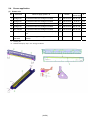
FIGURE 13
OPTION & CONSUMABLES
(51/58)
LIST OF FIGURE 13
FIGURE &
PART NUMBER RANK QTY
KEY No.
13-
1
2
3
4
DESCRIPTION
REMARKS
NPN
1
BLACK INK TANK CLI-221BK
CONSUMABLES
NPN
1
MAGENTA INK TANK CLI-221M
CONSUMABLES
NPN
1
YELLOW INK TANK CLI-221Y
CONSUMABLES
NPN
1
BLACK INK TANK PGI-220BK
CONSUMABLES
NPN
1
CYAN INK TANK CLI-221C
CONSUMABLES
NPN
1
BLACK INK TANK CLI-821BK
CONSUMABLES
NPN
1
MAGENTA INK TANK CLI-821M
CONSUMABLES
NPN
1
YELLOW INK TANK CLI-821Y
CONSUMABLES
NPN
1
BLACK INK TANK PGI-820BK
CONSUMABLES
NPN
1
CYAN INK TANK CLI-821C
CONSUMABLES
NPN
1
BLACK INK TANK CLI-521BK
CONSUMABLES
NPN
1
MAGENTA INK TANK CLI-521M
CONSUMABLES
NPN
1
YELLOW INK TANK CLI-521Y
CONSUMABLES
NPN
1
BLACK INK TANK PGI-520BK
CONSUMABLES
NPN
1
CYAN INK TANK CLI-521C
CONSUMABLES
NPN
1
BLACK INK TANK BCI-321BK
CONSUMABLES
NPN
1
MAGENTA INK TANK BCI-321M
CONSUMABLES
NPN
1
YELLOW INK TANK BCI-321Y
CONSUMABLES
NPN
1
BLACK INK TANK BCI-320PGBK CONSUMABLES
NPN
1
CYAN INK TANK BCI-321C
(52/58)
CONSUMABLES
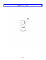
FIGURE 14
(53/58)
TOOL
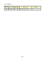
LIST OF FIGURE 14
FIGURE &
PART NUMBER RANK QTY
KEY No.
T-
1
QY9-0057-000
1
DESCRIPTION
LUBE, FLOIL KG107A, OIL
(54/58)
REMARKS
REFERENCE
PRINTER UNIT
(55/58)
SCREW & WASHER LIST
FIGURE &
PART NUMBER RANK QTY
KEY No.
S-
DESCRIPTION
1
XB4-7300-809
SCREW, TAP, BINDING HEAD, M3X8
2
XA9-1756-000
SCREW, TP, M3X8
3
XB4-7300-805
SCREW, TP, BH3X8
4
XB1-2300-405
SCREW, MACH.BH, M3X4
5
XA9-1752-000
SCREW, TAP, WASHER HEAD, M3X12
6
XB1-2300-605
SCREW, MACHINE, M3X6
7
XA9-1915-000
SCREW, SPRING W WASHER M3X10
8
XB6-7300-605
SCREW, MACHINE, TP, M3X6
9
XB4-7300-605
SCREW, BH M3X6
10
XA9-1783-000
SCREW, BINDING HEAD M2.6X3.5
(56/58)
REMARKS
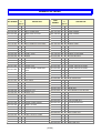
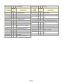
NUMERICAL INDEX
FIGURE
PART NUMBER
&
PART
DESCRIPTION
NUMBER
KEY No.
QC1-9023-000
FIGURE
&
DESCRIPTION
KEY No.
3-
1
EMBLEM
QK1-0776-000
1-
3
CORD, POWER
QC1-9024-000
3-
1
EMBLEM
QK1-1500-000
10-
4
MOTOR, CARRIAGE
QC2-7526-000
11-
1
BELT, PAPER FEED
QK1-2017-000
1-
3
CORD, POWER
QC2-7654-000
7-
3
GEAR, PICK UP SHAFT
QK1-3048-000
1-
3
CORD, POWER
QC2-7667-000
11-
3
BUSHING, PAPER FEED ROLLER
QK1-3761-000
1-
3
CORD, POWER
QC2-7671-000
11-
6
ABSORBER, INK
QK1-3849-000
12-
6
MOTOR, PAPER FEED
QC2-7682-000
12-
8
GEAR, IDLER
QK1-4512-000
8-
1
CABLE, CARD SLOT
QC2-7765-000
11-
4
FILM, TIMING SLIT DISK FEED
QK1-4815-000
8-
11 CABLE, PANEL
QC2-7783-000
10-
1
FILM, TIMING SLIT STRIP
QK1-4835-000
8-
9
CABLE, PE SENSOR
QC2-7841-000
3-
6
STAY, SCANNER
QK1-4965-000
2-
1
AC ADAPTER: 100V-240V 50/60HZ
QC2-7844-000
6-
2
CASE, MAIN
QK1-5002-000
8-
2
CABLE, PICTBRIDGE
QC2-7850-000
8-
4
PANEL, CARD
QK1-5034-000
8-
10 CABLE, LF ENCODER
QC2-7863-000
4-
2
HINGE
QL2-2525-000
11-
2
LF ROLLER ASS'Y
QC2-7870-000
5-
2
FRAME, PANEL
QL2-2528-000
10-
3
PULLEY HOLDER UNIT
QC2-7871-000
3-
9
TOP COVER, OPERATION REAR
QL2-2529-000
9-
2
PAPER FEED ROLLER ASS'Y
QC2-7872-000
3-
8
EDGE PANEL, OPERATION
QL2-2602-000
3-
7
COVER, OPERATION PANEL
QC2-7873-000
5-
1
GUIDE, LIGHT
QL2-2603-000
3-
7
COVER, OPERATION PANEL
QC2-7874-000
3-
10
QC2-7876-000
5-
QC2-7877-000
MIDDLE FRAME, OPERATION
QL2-2604-000
3-
7
COVER, OPERATION PANEL
REAR
QL2-2605-000
3-
7
COVER, OPERATION PANEL
7
KEY, START
QL2-2606-000
3-
7
COVER, OPERATION PANEL
5-
6
KEY, POWER
QL2-2607-000
3-
7
COVER, OPERATION PANEL
QC2-7878-000
5-
4
KEY, OK
QL2-2609-000
5-
16 LCD CABLE ASS'Y
QC2-7879-000
5-
5
JOG WHEEL
QM3-3598-000
10-
2
CARRIAGE UNIT
QC2-7882-000
5-
13 COVER, LCD FRONT
QM3-3610-000
9-
3
CASSETTE FEED GUID UNIT
QC2-7883-000
5-
17 COVER, LCD TOP
QM3-3614-000
10-
5
PRESSURE ROLLER ASS'Y
QC2-7884-000
5-
18 EDGE PANEL, LCD
QM3-3617-000
11-
7
SPUR UNIT
QC2-7885-000
5-
12 WINDOW, LCD
QM3-3618-000
11-
5
PLATEN/EJECT ROLLER UNIT
QC2-7886-000
5-
14 HINGE, LCD L
QM3-3619-000
12-
1
PURGE DRIVE SYSTEM UNIT
QC2-7887-000
5-
15 HINGE, LCD R
QM3-3633-000
9-
1
ASF UNIT
QC2-7908-000
7-
6
CASE, BOTTOM
QM3-3641-000
6-
1
REAR GUIDE UNIT
QC2-7919-000
5-
3
KEY, ARROW
QM3-3644-000
7-
4
PICK UP ARM UNIT
QC2-7921-000
8-
12 FRONT COVER, MIDDLE
QM3-3651-000
12-
2
PURGE MOTOR UNIT
QC2-7925-000
6-
5
SHEET, PE BIND
QM3-3681-000
6-
3
FRONT DOOR UNIT
QC2-7932-000
1-
4
LABEL, PANEL
QM3-3682-000
3-
4
SIDE COVER R UNIT
QC2-8026-000
5-
8
BASE, JOG WHEEL
QM3-3683-000
3-
5
SIDE COVER L UNIT
QC2-8523-000
8-
3
HOLDER, CORE
QM3-3684-000
3-
3
ASF COVER UNIT
QC2-9308-000
5-
11 LABEL, PRODUCT NAME
QM3-3685-000
1-
1
CASSETTE UNIT
QC2-9309-000
5-
11 LABEL, PRODUCT NAME
QM3-3689-000
3-
2
SCANNER UNIT
QC2-9324-000
4-
3
SHEET, DOCUMENT PRESSURE
QM3-3692-000
4-
1
DOCUMENT COVER UNIT
QH2-2716-000
1-
3
CORD, POWER
QM3-3694-000
6-
4
SUB CASE UNIT
(57/58)
QH2-2719-000
1-
3
CORD, POWER
QM3-3696-000
FIGURE
PART NUMBER
&
PART
DESCRIPTION
NUMBER
KEY No.
5-
10 LCD UNIT
FIGURE
&
DESCRIPTION
KEY No.
QM3-3707-000
8-
7
LOGIC BOARD ASS'Y
WT3-5156-000
1-
3
CORD, POWER
QM3-3708-000
8-
5
CARD BOARD ASS'Y
WT3-5160-000
1-
3
CORD, POWER
QM3-3709-000
5-
9
PANEL BOARD ASS'Y
XA9-1752-000
S-
5
QM3-3711-000
7-
1
FRONT DOOR LINK UNIT
S-
2
SCREW, TAP, WASHER HEAD,
M3X12
QM3-4278-000
7-
2
DC HARNESS ASS'Y
XA9-1756-000
QM3-4445-000
12-
7
LF MOTOR HARNESS ASS'Y
XA9-1783-000
S-
10 SCREW, BINDING HEAD M2.6X3.5
QM3-4449-000
12-
3
MOTOR MULTI HARNESS ASS'Y
XA9-1915-000
S-
7
QM3-4451-000
8-
8
PE SENSOR BOARD ASS'Y
S-
4
SCREW, MACH.BH, M3X4
12-
4
PAPER FEED RELAY HANESS
XB1-2300-405
QM3-4453-000
ASS'Y
XB1-2300-605
S-
6
SCREW, MACHINE, M3X6
S-
9
SCREW, BH M3X6
SCREW, TP, BH3X8
QM3-4467-000
8-
6
PICTBRIDGE BOARD UNIT
XB4-7300-605
QM3-4757-000
9-
4
PAPER GUIDE UNIT
XB4-7300-805
S-
3
QM3-5094-000
12-
5
SWITCH SYSTEM UNIT
XB4-7300-809
S-
1
QY5-0239-000
7-
5
ABSORBER KIT
QY6-0073-000
1-
2
PRINT HEAD
XB6-7300-605
S-
8
QY9-0057-000
T-
1
LUBE, FLOIL KG107A, OIL
(58/58)
SCREW, TP, M3X8
SCREW, SPRING W WASHER
M3X10
SCREW, TAP, BINDING HEAD,
M3X8
SCREW, MACHINE, TP, M3X6