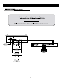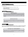
1
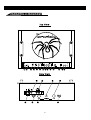
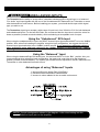
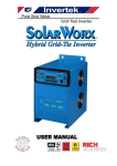
Owner´s Manual
and
Installation Guide
CONGRATULATIONS!
You now own the Limited Edition Tarantula Amplifier, the product of an uncompromising design and
engineering philosophy. Your Soundstream Tarantula will outperform any other amplifier in the world.
To maximize the performance of your system, we recommend that you thoroughly acquaint yourself with
its capabilities and features.Please retain this manual and your sales receipt for future reference.
Soundstream amplifiers are the result of American innovation and the highest quality control standards.
When properly installed, they will provide you with many years of listening pleasure.Should your amplifier
ever need service or replacement due to theft, please record the following information which will help
protect your investment.
Serial #
Dealer's Name
Date of Purchase
Installation Shop
Installation Date
CAUTION!
Prolonged listening at extremely high levels may result in hearing loss.Even though your new Soundstream
Tarantula amplifier sounds better than anything you've ever heard, exercise caution to prevent hearing
damage.
2
TABLE OF CONTENTS
Features
p 4 -5
Tarantula Diagram
p6-7
Balanced/Unbalanced Inputs
p8
Wiring
p9
Installation and Mounting
p 10
Crossover Adjustments
p 11
Hawkins Bass Control™ Theory and Use
p 12 ~ 13
Level Setting
p 14
Power Supply Programming
p 15
Troubleshooting Chart
p 15
Sample System
p 16
Protection Circuitry
p 17
Very Serious Warnings
p 17
Service
p 17
Specifications
p 18
3
FEATURES
RUBI™ (Rapid-Use Branched Impulse) This new proprietary power supply topology eliminates “power
sags"during low frequency reproduction by rapidly increasing the duty cycle, stabilizing the power
supply and allowing it to deliver the power required when reproducing low frequencies. Also, greater
reserve gate power is stored for low voltage conditions that occur during extreme conditions.
STACT™(STabilized Apex Current Topology) Reduces power supply stress by 50%. In The STACT
design, inversion is done at the power amplifier drive stage. Since the fully symmetrical power amplifier
produces no even-harmonic distortion itself and all preamplifier circuitry is run completely inphase,no
even harmonic distortion phase reversal occurs and power is better distributed throughout the amplifier.
Advanced Trident™ Protection Topology Protects against potential harm/damage in the following
situations:
1. Output Protection against short circuits or improper loads.
2. Voltage Inconsistencies protects against ground fault (speaker shorts to vehicle chassis) and an
under/over voltage condition on the battery input.
3. Thermal Protection puts the amplifier into thermal rollback or shuts the amplifier down in extreme
thermal conditions.
Tone Sweep Calibration Routine Automatically configures and optimizes the power supply to the
connected speaker load.
Hawkins Bass Control Provides a focused parametric subwoofer boost (0 to +9 dB between 13-70 Hz)
and routes otherwise wasted amplifier power back to the audible bandwidth.
Continuously Variable Crossover Networks 24 dB/octave low pass crossovers variable from 35 Hz to
500k Hz with a range selection switch.
Input Level Indicator A three colored LED that provides visual confirmation of the amplifier’s input level
sensitivity setting.
Output Clipping Indicators Indicates clipping on the output stage of the amplifier. Monitoring the clipping
indicators allows the user to achieve maximum SPL without clipping the amplifier.
Large Mouth Bass Remote subwoofer volume control built into the amplifier
4
FEATURES
Output Phase Switch O-180 degree phase control switch.
Fan Cooling With thermally sensitive speed control.
Differentially Balanced RCA Input Eliminates ground loop related noise in the audio signal.
Fully Balanced 6-pin DIN Input For professional quality performance and noise cancellation. The 6-pin
DIN plug carries ( ) signal information for left and right channels, audio ground, and 15Vdc to
operate the Soundstream BLT/ BLT4 Balanced Line Transmitters and Balanced X.0 crossover.
RCA Line Output Provides a full range signal output to drive other amplifiers.
Wire Connections Power and ground connections accept 1\0 gauge cable, while the speaker
connections utilize dual 4 gauge connections.
Harmonic Bass Alignment™ The 2nd and 3rd order harmonic peaks are critically aligned to
fundamental peaks at low frequencies. This produces tighter,more accurate bass reproduction.
Symmetrical Discrete Balanced Class A Drive Boards Auto-adjust for linear performance while driving
low impedance loads.
Drive Delay II™ Amplifier section powers up 2 to 3 seconds after the power supply, eliminating turn-on
pops. Turn off process is reversed; amplifier section turns off first, followed by the power supply.
Chassisink™ All transistors are ideally located and sandwiched between the circuit board and the
heatsink to provide cool efficient amplifier operation.
Dynamically Optimized Power Grid™ Power grid is evenly distributed between primary and secondary
power supplies, providing greater dynamics and improved RF filtering.
5
TARANTULA DIAGRAM
6
KEY TO CALLOUTS
1. Input Level LED -Warns of the onset of clipping.
2. Amplifier Clip LED - Indicates clipped amplifier output.
3. Left Channel Balanced/ Unbalanced Input Switch -Select ‘Balanced’ to use the 6-pin balanced
signal input. Select ‘Unbalanced’ to use the RCA signal inputs.
4. Right Channel Balanced/ Unbalanced Input Switch- Select ‘Balanced’ to use the 6-pin balanced
signal input. Select ‘Unbalanced’ to use the RCA signal inputs.
5. Input Level- Input level control.
6. Hawkins Bass Control/ Subsonic Switch - Select ‘SUBSONIC’ to engage the Subsonic filter
between 13 Hz and 30 Hz with no boost. Select Hawkins Bass Control’ to engage the Subsonic filter
between30 Hz and 70 Hz with an adjustable boost determined with the Q boost control.
7. Hawkins/Subsonic Frequency Adjustment- Frequency adjustment control for the Hawkins Bass
Control or the Subsonic filter.
8. Hawkins Bass Control Boost Adjustment - Varies from 0 to +9dB of boost when the Hawkins
Bass Control circuit is engaged.
9. Low Pass Filter Adjustment - Frequency adjustment for the low pass filter.
10. Low Pass Filter Range Switch - Frequency range selection for the low pass filter.
11. Power/Calibration Switch- Push button switch that selects power level or when pushed and
held for a short time, then released, the amplifier auto-adjust to the speaker load.
12. Phase Switch -Adjusts the speaker phase to either 0 or 180 degrees.
13. Power LED - Indicates amplifier power (see chart on page 16).
14. Status LED - Indicates amplifier status; thermal, short circuit, etc...
15. RCA Inputs - Right and Left channel RCA inputs.
16. Balanced Signal Input Connector - 6- pin balanced input connector for use with the Soundstream
BLT/BLT4 Balanced Line Transmitter.
17. RCA Line Outputs - Right and Left channel RCA fullrange outputs.
18. Negative Speaker Terminals- Negative 4 gauge speaker connection.
19. GND - Main ground connection. Bolt to a clean chassis point in the vehicle.
20. Remote - Remote turn-on input from the head unit. Accepts 12V.
21. 12V - Connect to a fuse or circuit breaker, then to the batteryís positive terminal.
22. Positive Speaker Terminals - Positive 4 gauge speaker connection.
7
BALANCED/ UNBALANCED INPUTS
The Tarantula has the ability to accept either a standard unbalanced RCA signal input, or a balanced
“Pro Audio” style input signals with the use of the Soundstream BLT Balanced Line Transmitter or some
other balanced line audio source. Before installing your system, you should decide upon which signal
type you wish to run.
The Tarantula’s signal input accepts a wide range of input level: from 300mV to 5.0V for both balanced
and unbalanced inputs. For the best S/N Ratio, we recommend that the input level control be set as far
down as possible (rotated counterclockwise), while maintaining an acceptable level of output.
Using the “Unbalanced” RCA Input
When using the unbalanced RCA input, the RIGHT channel input signal switch MUST be in the ‘UNBAL’
position. Also, when first installing the amplifier using this input configuration, we suggest that the left
channel input signal switch be in the ‘UNBAL’ position as well. If you experience alternator whine or
other installation noise with both switches in the ‘UNBAL’ position, try moving the LEFT channel
input signal switch to the ‘BAL’ position. This should remove any system noise due to the installation.
Using the “Balanced” Input
When using the balanced B-pin DIN audio input, the switches MUST be in the ‘BAL ’ position. Also, we
recommend that when using this input configuration, the input level control be set to the “minimum”
position (rotated counterclockwise). The system gain should then be adjusted on the BLT Balanced Line
Transmitter or other balanced line audio source.
Advantages of using “Balanced” Inputs
1. Improved Signal to Noise Ratio (SIN Ratio).
2. Excellent noise cancellation characteristics.
3. Immune to noise radiated in the car audio environment.
NOTE: The pin configuration shown in the diagram is the view looking into the
Balanced input jack on the amplifier.
8
WIRING
Power and Ground
To ensure maximum output from your Tarantula amplifier, use high quality, Lowpass power and
ground cables and connections. The Tarantula amplifier will accept up to 1/0 gauge power and
ground cables.
Circuit Breakers and Fuses
External
Like all audio components, the Tarantula amplifier must be fused near the battery.
A 300 amp fuse or circuit breaker must be located within 18” of the battery. This will prevent a fire in the
event of a shorted cable.
Internal
The Tarantula amplifier is fused with a 300 amp blade-type (ANC) fuse. In the event of a blown
power supply fuse, replace with the correct value fuse. Never replace the fuse with a higher
value than what is supplied. This may result in amplifier damage and will void the warranty!
Remote Turn-On
Connect the turn-on lead from the source unit to the ìRemoteî input on the amplifier. When +12
volts is received, the amplifier will turn on.
Signal Cable
Depending on your application, you may use either the DIN audio balanced signal cable or
standard RCA cables to drive your Tarantula amplifier.
Speaker Cable
The Tarantula will accept up to a 4 gauge speaker cable. Use high quality, flexible, multi-strand
cable for best performance and longevity.
9
INSTALLATION AND MOUNTING
Amplifier Location
The Tarantula amplifier employs highly efficient circuitry, a custom-engineered heatsink, and a unique
Chassisink™ construction to maintain lower operating temperatures. Additional cooling may be required
if the amplifier is located in a tightly confined area or when driving especially low impedance loads at
extremely high levels.
When mounting the amplifier, it should be securely mounted to a panel in the vehicle or an amp board or
rack that is securely mounted to the vehicle. The mounting location should be either in the passenger
compartment or in the trunk of the vehicle, away from moisture, stray or moving objects, and major
electrical components.
To provide adequate ventilation, mount the amplifier so that there are at least four inches of freely
circulating air above it and at the intake vents on each side of the amplifier.
Mounting The Amplifier
a. Using the amplifier as a template, mark the cut out on the mounting surface.
b. Remove the amplifier and cut out the hole to mount the amplifier.
c. Secure the amplifier to the mounting surface using the supplied hardware.
Wiring
a. Run and connect the audio signal and remote turn-on cables to the amplifier from the source unit.
b. Carefully ’run the positive cable from the amplifier to a fuse or circuit breaker within 18” of the battery.
c. Connect the fuse or circuit breaker lead to the battery. Leave the circuit breaker off or the fuse out until
everything is bolted down.
d. Secure the ground cable to a solid chassis ground on the vehicle. It may be necessary to sand paint
down to raw metal for a good connection.
e. Double check each and every connection!
f. Reconnect the fuse or circuit breaker.
Power Up
Power up the system, there may be a 2-3 second delay from the time the source unit is turned on to the
time that the amplifier turns on, which is normal. Once the amplifier LED is on and the source unit is
playing, you should have sound coming from the speakers.
10
CROSSOVER ADJUSTMENTS
The Tarantula amplifier incorporates two separate electronic crossovers. A 12dB\octave Subsonic
filter and an on-board 24 dB\octave electronic low pass crossover, with full range RCA outputs to
drive an external amplifier. No external electronic crossover is required when operating this amplifier.
Subsonic
The Subsonic filter allows the amplifier to focus all of its energy where it is needed most. Adjust the
filter to the tuning frequency of a ported box and increases in output will be noticed immediately. The
Subsonic filter is variable from 13 to 30 Hz.
The shaded area below shows the frequency and range adjustments as they appear on the control
panel of the amplifier.
Low Pass
The Low Pass filter is variable from 35 to 500 Hz, which is divided into two separate ranges: “Low” and
“High”. The “Low” range will yield a frequency range from 35 to 135 Hz, while the “High” is from 135 to
500 Hz.
The shaded area below shows the frequency and range adjustments as they appear on the control
panel of the amplifier.
11
HAWKINS BASS CONTROL™ THEORY AND USE
Hawkins Bass Control (parametric) is a unique subwoofer control circuit included with the Tarantula
amplifier. It is capable of removing subsonic energy in program material while boosting subwoofer
frequencies. The circuit consists of two controls. One adjusts the frequency of operation and the other adjusts
the range of boost. With both controls adjusted fully counterclockwise, no boost is applied and the amplifier is
flat in response down to 20 Hz.
The frequency control (Hz) adjusts the starting point of
the subsonic filter.
On the Tarantula, the high pass filter has two frequency
ranges. When the bass control switch is set to ‘SUBSONIC’,
the high pass filter frequency can be adjusted from 13 Hz up
to a maximum of 30 Hz. In this setting, no boost “Q” control is
available. This control is useful for setting the lowest
frequency that your subwoofer will see. When the bass control
switch is set to ‘HAWKINS BASS CONTROL’, the high pass
filter frequency can be adjusted from 30 Hz to a maximum of
70 Hz. In this setting, there is an available boost control of 0 to
+9dB.
Fig. 1 Variable “Q”
Fig. 2 Variable High Pass
The Boost control adjusts the level applied at the set
frequency.
This is adjustable from flat 0 dB to + 9dB (See figure 1).
When the ‘Boost’ is set to 0, Hawkins acts as a subsonic
filter only (See figure 2). The simple act of removing
potentially harmful low frequencies can improve system
output by as much as 3 dB (See figure 3.)
Fig. 3 Variable Boost
12
Application
Subwoofers in general have excellent power handling
characteristics over their operational bandwidth. This
bandwidth is determined by many factors, including driver
design, and enclosure type. It is possible to overdrive any
subwoofer by sending powerful signals outside of its
operational bandwidth. These potentially damaging signals can
be removed by adding a subsonic filter. Figure 4 shows the
effectiveness of the Hawkins Bass Control on woofer excursion
in a vented enclosure. The woofer travels 7.5 mm at 10 Hz.
With Hawkins Bass Control properly adjusted, this excursion
can be reduced to less than 1 mm. This is of great benefit to
lowering woofer distortion and increasing output.
Fig.4 Limited Excursion
Adjustment
An easy method of optimizing your existing subwoofer enclosure with Hawkins ‘Hz’ control is as follows
(assuming the audio system is already turned on).
1. Adjust frequency and boost control to full counterclockwise position.
2. Set the bass control switch to ‘HAWKINS BASS CONTROL’.
3.While listening to music with strong bass content at a moderate level, slowly adjust frequency control
clockwise. Listen for a reduction of bass response. Now, rotate frequency control slightly backwards.
This serves the purpose of removing the ‘subsonic’ bass energy.
With Soundstream’s Hawkins Bass Control, the boost and frequency control can provide virtually any
combination of boost and cut to suit your designs. So, Hawkins Bass Control can provide the ‘tailoring’
needed for any type of ‘assisted’ design and any woofer in any type of installation.
The shaded area below shows the Hawkins Bass Control adjustments, crossover range switch and
frequency as they appear on the control panel of the amplifier.
13
LEVEL SETTING
The input level is adjusted by means of the input level control located on the control panel of the amplifier.
This is a unique dual-stage circuit that adjusts both level and gain. This topology maintains better S/N Ratio
even when using sources with minimal output.
In the ideal situation, all components in the audio system reach maximum undistorted output at the same time.
If you send a distorted signal to an amplifier, it is simply going or crossover begins to distort before you have
maximum output from the amplifier. By setting all components to reach clipping at the same time, you can
maximize the output of your system. For the Tarantula, follow these steps for setting the input levels:
1. Turn the amplifier’s input level to minimum position (counterclockwise).
2. Set the source unit volume to approximately 3/4 of full volume.
3. While playing dynamic source material, slowly increase the amplifier’s input level until a near maximum
undistorted level is heard in the system. This can be visually verified by the input level indicator. The0
input level light has three levels of indication; Green (normal), Amber (1 0dB below clipping), Red (near
clipping).
The clipping indicator on the top of the amplifier will let you know when the output of the amplifier is reaching
its maximum level, and has begun to clip.
The shaded area below shows the input and output clip indicators, Large Mouth Bass switch and input level
as they appear on the control panel of the amplifier.
14
POWER SUPPLY PROGRAMMING
Push Buttons
Power / Calibration
Momentary Press
(less than half second)
Go to next speaker load power level
4 0HM
(Red)
2 0HM
(Amber)
1 0HM
(Green)
Hold and Release
(more than second)
Automatically set the power level by
running the speaker load calibration
routine.
TROUBLE SHOOTING CHART
Condition
Normal
Thermal Rollback
Power LED
Red
Amber
Green
(4 ohm)
(2 ohm)
(1 ohm)
Red
Amber
Green
(4 ohm)
(2 ohm)
(11 ohm)
Status LED
off
Blip
(On: o.1 sec., Off: 1.9 sec.)
Under I Over Battery Input
voltage
off
Fast Blink
(On: o.05 sec., Off: 0.1 sec.)
Short Circuit /Overload
off
Medium Blink
(On: o.05 sec., Off: 0.1 sec.)
Over Temperature,
Ground Fault, Tun On / Off
off
On
NOTE:
At low signal levels the INPUT LEVEL LED is variable green in color.
With greater signal level the INPUT LEVEL LED begins to appear amber approximately 10dB
below amplifier output clip.
With extreme signal levels the INPUT LEVEL LED snaps red within 0.5dB of amp output clip.
Amplifier output clipping can be identified by a solid red AMP CLIP LED.
The 1 ohm power level is not a recommended set up for full power output; at times of reduced
volume the 1 ohm power level can be used with actual 2 or 4ohm speaker loads to save energy
draw from the vehicleís electrical system (i.e.extend battery life).
15
SAMPLE SYSTEM
16
PROTECTION CIRCUITRY
Your Tarantula is protected against both overheating and short circuits by means of a main power fuse and
the following circuits:
Under/ Over battery input voltage (between 8.5Vdc and 17.0Vdc)
Speaker Output Protection
Ground Fault Differential
Variable speed fan cooling with smart power supply thermal roll back
Temporary over temperature shutdown with high speed fan cooling
SERIOUS WARNINGS
IMPORTANT(VERY)!!!
If you experience blown main powers supply fuses it is likely that the amplifier is
seeing a dead short either in the speaker wire or in the speaker itself. Rectity the
problem before blowing multiple fuses! DO NOT increase valuse beyond the
origianl fuse value! Doing so will void your warranty and may damage your
amplifier.
IMPORTANT(VERY VERY)!!!
When the signal is being greatly amplified care must be taken while handling the
speaker leads which may present potentially lethal voltages (possibly exceeding
100Vrms at clip)
SERVICE
Your Soundstream Tarantula is protected by a limited warranty. If an authorized dealer installs the
amplifier, it is under warranty for a period of three years, a consumer installed unit is warrantied for a
period of one year. Please read the enclosed warranty card for more details and be sure to send it in.
** NOTE ABOUT THE LIMITED WARRANTY**
If the handles or the top of the amplifier are removed for any reason, the warranty
will be void. There are no user serviceable parts in the amplifier this eliminates
the need to ever open the top of the unit.
17
SPECIFICATIONS
POWER
4 Ohm Mono
(12.6Vdc)
4 Ohm Mono
(14.4 Vdc)
2 Ohm Mono
(14.4 Vdc)
Maximum
Rated
Output
2000W x 1
2000W x 1
2000W x 1
2000Watts
Tarantula
T.H.E
Signal to Noise Ratio
Frequency
Damping
input Sensitivity
Input Impedance
<0.3%
>90 dB
20Hz ( 0.5dB) to 500 Hz (-3 dB)
>200
300mV to 5.0V
10k Ohms
Crossover Specifications
24dB/octave Low Pass filter adjustable from 35 to 135 Hz(lower setting)
24 dB/octave Low Pass filter adjustable from 135 to 500 Hz (higher setting)
Subsonic Filter
No boost; 12 dB/octave High Pass filter from 13 to 30 Hz.
Hawkins Bass Control
0 to +9dB boost; Boost and Subsonic filter variable from 30 to 70 Hz.
Dimensions (W x D x H)
Tarantula: 19.0¨ X 14¨ X 5.5¨
18
SOUNDSTREAM TECHNOLOGIES
1550 Maple Avenue., Montebello, CA90640 U.S.A.
Phone 323-722-3333 fax. 323-722-1122