1
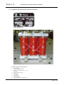
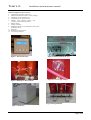
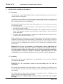
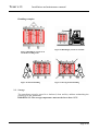
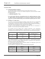
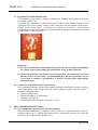
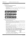
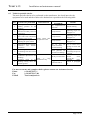
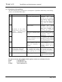
Tesar s.r.l.
Installation and maintenance manual
Installation, use and maintenance
Manual
Page :1\20
Tesar s.r.l.
Installation and maintenance manual
1.
INTRODUCTION
1.1. Reference Standards
1.2. Outline of the transformers and the accessories
2.
RECEPTION, HANDLING, STORAGE
2.1. Reception
2.2. Transport and handling
2.3. Storage
3.
INSTALLATION
3.1. Standard installation conditions
3.2. Windings over temperature
3.3. Dimensioning of air replacement
3.4. Insulating distances
3.5. Earthing connections and protections
3.6. HV and LV connections
3.7. Transformation ratio adjustment
3.8. Parallel connection of several transformers
4.
TRANSFORMER PROTECTION
4.1. Temperature control system
4.2. Overloading and short circuit protection
4.3. Protection against overvoltages
5.
COMMISSIONING
5.1. Mechanical checks before the commissioning
5.2. Electrical checks before the commissioning
5.3. Operations for the commissioning
6.
MAINTENANCE, ASSISTANCE SERVICE
6.1. Ordinary maintenance
6.2. Extraordinary maintenance
6.3. Table for periodical checks
6.4. Problems solving
Page :2\20
Tesar s.r.l.
1
Installation and maintenance manual
INTRODUCTION
1.1. Reference Standards
The cast resin transformer referred to the attached test report, has been designed and
manufactured by TESAR in order to meet to Italian CEI and international IEC Standards
requirements in force at the moment of its manufacturing (unless different agreement) as
well as to meet the client specifications.
• CEI Standards (Italian)
-
CEI 14-8
-Trasformatori di potenza a secco- Generalità
CEI EN 60076-1 - Power transformer – part 1 : General
CEI EN60076-2 - Power transformer – part 2 : Temperature Rise
CEI EN 60076-3 - Power transformer – part 3 : Insulation levels,
dielectric tests and external clearances in air
CEI EN 60076-4 - Power transformer – part 4 : Guide to the lightning
impulse and switching impulse testing - Power transformers and reactors
CEI EN 60076-5 - Power transformer – part 4 : Ability to withstand short
circuit
CEI EN 60076-10 - Power transformer- part 10 determination of sound
levels
CEI 14-7
- Marcatura dei terminali dei trasformatori di potenza
CEI 14-12
-Trasformatori trifasi di distribuzione di tipo a secco 50
Hz , da 150 a 2500 kVA con tensione massima per il componente non
superiore a 36 kV -parte 1: Prescrizioni generali e prescrizioni per
trasformatori con una tensione massima per il componente non superiore a
24 kV
• IEC Standards (International)
-
IEC 60726
-Dry-type power transformers:General
IEC 60076-1
- Power transformer – part 1 : General
IEC 60076-2
- Power transformer – part 2 : Temperature Rise
IEC 60076-3
- Power transformer – part 3 : Insulation levels,
dielectric tests and external clearances in air
IEC 60076-4
- Power transformer – part 4 : Guide to the lightning
impulse and switching impulse testing - Power transformers and reactors
IEC 60076-5
- Power transformer – part 4 : Ability to withstand short
circuit
IEC 60076-10
- Power transformer- part 10 determination of sound
levels
IEC 60616
-Terminal and tapping markings for power transformers
HD 538.1 S1
- Three-phase dry type distribution transformers 50Hz,
from 100 kVA to 2500 kVA with highest voltage for equipment not
exceeding 36 kV-part 1 general requirements and requirements for
transformers with highest voltage for equipment not exceeding 24 kV
Page :3\20
Tesar s.r.l.
Installation and maintenance manual
Electromagnetic compatibility
The intensity of low frequency magnetic field emitted by the windings is of a limited
value and, however, it is equal or lower than those of the field emitted by the connections
and the low voltage bars.
Its value quickly decreases by increasing of the distance from the transformer. The
intensity of the magnetic field can be significantly reduced by installing the transformer
inside a metal enclosure (housing).
The temperature control device or other auxiliary connections, included the thermoresistances, for the protection against electromagnetic disturbances conform to the
Standard CEI EN 50081-2 (IEC 50081-2) and CEI EN 50082-2 (IEC 50082-2).
Marking CE
TESAR does not affix the marking CE on its transformers as foreseen at paragraph 5.4.2
of the “Guide to the application of the Directive 89/336/EEC” which excludes from the
Directive application field:
• High voltage inductor
• High voltage transformer
Page :4\20
Tesar s.r.l.
Installation and maintenance manual
1.2. Outline of the transformers and the accessories
Figure 1 Rating Plate
sideways travel
10.
Standard components and accessories
1. Tow attachment
2. Links for voltage variation
3. Pt100 thermo-resistances on the
windings
4. Auxiliary connection box
5. Lifting eyes
6. LV terminals
7. HV terminals
8. Ground terminal
9. Truck with rollers for lengthways or
Page :5\20
Tesar s.r.l.
Installation and maintenance manual
Optional components and accessories
1
Pt100 thermo-resistance on the core
2
Double Pt100 thermo-resistance on the windings
3
Thermistors on the windings/Core
4
Tangential fans for power increase
5
Metallic screen between primary and
secondary connected to the ground
6
Rubber wheels
7
Thermo-controller
8
Multifunctional device for temperature and electric
parameters check
9
Enclosure
10 Bushings for HV terminals
11 Cover for tap-changers
Figure 3 Thermocontroller
Figure 4 Double Pt100 on the core
Figure 5 Bushing for HV terminals
Figure 6 Cover for tap-changer
Figure 8 Tangential fans
Figure 7 Enclosure
Page :6\20
Tesar s.r.l.
2.
Installation and maintenance manual
RECEPTION, HANDLING, STORAGE
2.1. Reception
The transformer is generally supplied totally assembled and ready to be connected to the
medium and low voltage line.
According to the specification, the transformer is shipped with a polythene protection, or
packed into wooden cage, for protection against dust and little shocks, or finally packed
into a wooden case for over-sea shipments.
On receipt of the transformer, both at the client's plants or site, it is necessary to carry out
the following checks:
• To check there are not signs of damage on the packing or the transformer occurred
probably during the transport.
• The characteristics of the transformer detailed on the rating plate must correspond to
those of the shipping documents and with those of the test report, which is attached
to the transformer.
• To check that each transformer is complete with the accessories foreseen in the
contract (wheels, thermo-controller etc.).
Before unpacking the transformer, especially during winter period when the temperature
difference between the room and the outdoor is considerable, it is necessary to wait for a
period of at least 8-24 hours in such a way that the temperature of the transformer has the
necessary time for reaching that of the room, in order to avoid water condensation on the
coils surface.
IMPORTANT: In case any anomalies are found, please contact immediately the
manufacturer. If within 5 days there will be no notification of anomalies or defects,
it can be considered that the transformer has been delivered in perfect conditions.
The manufacturer, therefore, cannot be considered responsible neither for what
could happen to the transformer during service nor for the eventual consequences.
2.2. Handling
During the transport or the handling, it is recommended to use only the special lifting
eyes and tow attachments.
IMPORTANT: The transformer cannot be moved pushing the coils and the
connections.
For locating the transformer in the final position, act only by means of a suitable lever on
the special points foreseen on the lower frames and not on the magnetic core and/or on
the windings.
For lifting, the upper frame of the transformer is complete with nos. 4 lifting eyes for
slings. Lift with a maximum sling angle of 60°.
If the transformer is complete with protection enclosure, take off the roof to attach
the slings.
Page :7\20
Tesar s.r.l.
Installation and maintenance manual
Handling examples
Figure 9 Handling by means of an
overhead-travelling crane
Figure 11 Manual handling
Figure 10 Handling by means of a forklift
Figure 12 Wrong manual handling
2.3. Storage
The transformer must be stored in a sheltered, clean and dry ambient maintaining the
packing up to the installation.
IMPORTANT: The storage temperature must not be lower than -25°C.
Page :8\20
Tesar s.r.l.
Installation and maintenance manual
INSTALLATION
3.1. Standard installation conditions
The maximum height of installation must not exceed 1000 m above sea level.
When the transformer is in service, the ambient temperature of the room must be within
the following limits:
• Minimum temperature: -25°C
• Maximum temperature: + 40°C
In case the height of the place of installation and/or the ambient temperature values
are higher that the ones specified above, it is necessary to specify it at the ordering
stage since a particular dimensioning of the transformer depends upon these values.
3.2. Windings over temperatures
The electric current passing through the windings, and the effect of the core magnetising
current produce electrical loss resulting in localised heating of the core and windings.
The transformer is designed in such a way that natural cooling maintains the transformer
temperature under the maximum values foreseen by the standards.
In order to avoid temperature accumulation in the room where the transformer is
installed, it is necessary to provided suitable ventilation.
The standard (with max ambient 40°C) winding temperature of the transformers
designed to work in standard conditions, as foreseen at par. 3.1., change as a function of
the insulation class and they must not exceed the limits specified on the following table:
Insulation class
Medium windings
temperatures °C
Maximum temperature of the
insulating system °C
B
120
130
F
140
155
Each TESAR transformer, is complete with at least nos. 3 PT100 thermo-resistance
probes, one for each low voltage winding and wired to a junction box for connection to
the thermo-controller usually supplied loose.
For connecting and setting the thermo-controller against over temperature, please read
the relative manual attached to the same.
For the regulation we suggest the values showed on the following table:
Insulation class
Alarm °C
Trip °C
B
100°C
120 °C
F
120°C
140°C
Page :9\20
Tesar s.r.l.
Installation and maintenance manual
3.3. Dimensioning of air louvers
• Natural cooling
In the room where the transformer is installed, it is necessary to install air louvers
sufficient to dissipate the heat during service, in order to guarantee the standard
service conditions and to prevent the transformer from exceeding the over
temperature limits.
Therefore the room must be provided with a louver on the lower part S, in order to
guarantee an appropriate fresh air flow; and a louver S’ on the upper part of the
opposite wall, in order to extract the hot air due to the "chimney effect" (figure 13).
For a correct dimensioning of the louvers on the room, use the following formula, to
calculate the surface of the louvers for air incoming and outgoing, for a nominal
annual ambient temperature of 20°C.
P
S ≡ 0.188 ⋅
S ' ≡ 1.10 ⋅ S
where:
H
P
S
S’
H
=
=
=
=
Sum of the transformer no-load losses and the load losses at 120°C in kW.
Surface of the incoming louver in m2
Surface of the outgoing louver in m2
Height between the two louvers in meters
Figure 13 Natural cooling
• Forced cooling
Forced cooling is necessary in the following cases:
• Frequent overloading
• Low-dimensioned room
• Room scarcely ventilated
• Medium daily temperature higher than 30°C.
Page :10\20
Tesar s.r.l.
Installation and maintenance manual
The forced cooling can be realized by means of:
•
•
Tangential fans or other technology, installed directly during the manufacturing
stage or added successively at site, dimensioned as a function of the transformer
power and of the over temperature to be dissipated.
Installation of air extractor located in the upper part of the room (or the
enclosure) controlled by a suitable thermostat or directly by a transformer
thermal protection relay, with a suggested flow of approx. 3,5÷4 m3/min. for
each kW of losses at 120 °C.
ATTENTION: an insufficient air circulation, besides reducing the nominal
life of the transformer, causes over heating which, in the worst cases, can
determine the intervention of the thermal protection relay.
3.4. Insulating distances
The transformer supplied for service without enclosure (IP00) must be installed in the
relative room respecting the insulating distances specified here under.
The transformer must be protected against direct contacts; it must be remembered that
the resin be considered as a part under voltage.
Furthermore it is necessary:
• To eliminate the risk of water dripping on the transformer.
• To respect the minimum distances towards the walls and towards ground as a
function of the insulating voltage according to the following table.
Figure 14 Insulating distances
Page :11\20
Tesar s.r.l.
Installation and maintenance manual
Insulation
Distance “D” mm
KV
Concrete Wall
Grilled
7,2
150
300
12
150
300
17,5
220
300
24
240
300
36
320
320
3.5. Earthing connections, taps and protection position
Tesar is not responsible for the transformer installation. The installation must be carried
out according to the standards in force, to the applicable laws and to the present
instructions.
The following points must be taken into consideration when the installation is carried
out:
• To connect the earthing conductors to the relative earth points on the metallic parts of
the transformer and enclosure.
• To connect the low voltage neutral to earth when required or when required by the
protection system to earth.
• To connect the thermal protection to the control system according to the sketch as
shown in the thermal protection relay manual (thermo-controller).
• To ensure that the connection means of the primary winding are safely bolted.
• To ensure that the voltage regulation taps are safely bolted, and if necessary modify
the position as a function of the supply voltage.
Note : At the time of shipping, the links of the voltage tap-changer are located on
the central tap.
• In case of transformers with double ratio, please be sure that the link corresponding
to the voltage of the system feeding the transformer is properly connected.
Note: At the time of shipping, the links of the voltage tap-changer are connected on
the position corresponding to the nominal voltage.
3.6. LV and HV connections
• Execution without enclosure (IP00)
The cables and the bus bars which are connected to the transformer must be duly
fixed to avoid any mechanical stress on the LV and HV transformer terminals.
Both upper and bottom cable connections can be performed, being sure, however, to
respect the configuration showed in the drawings. In case the connections arrive from
the bottom please ensure that there is sufficient depth for the minimum radius of
curvature of the cables.
Page :12\20
Tesar s.r.l.
•
Installation and maintenance manual
Execution with protection enclosure
The cables and the bus bars which are connected to the transformer must enter the
enclosure only through suitable flanges specified at the ordering stage.
In any case the cables and/or the bus bars must be duly fixed outside the enclosure to
avoid any mechanical stress on the LV and HV terminals of the transformer. After
the installation please check the correct degree of protection is maintained near the
passageway of the cables and the bus bars.
Figure 15 Cables coming from the top
Figure 17 Conductor fixing
Figure 16 Cables coming from the bottom
Figure 18 Cables fixing on the enclosure
Page :13\20
Tesar s.r.l.
Installation and maintenance manual
3.7. Regulation of transformation ratio
The variation of the primary voltage is obtained by changing the position of the link
located on each HV coil.
Generally, the transformer is delivered with the link of each column located in the
central tap. In case the primary voltage of the system does not correspond exactly to the
voltage of the central tap, it is necessary to modify the position of the tap duly
positioning it on one of the other taps in order that the secondary obtained is the no-load
voltage shown on the rating plate.
Figura 19 Tap-changer
Important
A) In case of transformers with double ratio, please be sure the tap corresponding
to voltage of the system feeding the transformer it-self, is duly connected.
B) In case the position of the link has to be changed after the transformer has been
put into service the first time, it is recommended to put the transformer out of
service and to connect to ground the LV and HV circuits before approaching
the transformer.
3.8. Connection in parallel of more transformers
If the transformer must be connected in parallel with other transformers, please verify the
total compatibility of the voltage ratio and of the conditions stated by the IEC 60076-1
standards, and particularly:
• Identical voltage ratio
• Identical frequency of functioning
• Identical vector group
• Identical short circuit voltage (Tolerance ± 10%)
4.
TRANSFORMER PROTECTIONS
4.1. Over temperature protection by thermo-controller
Each TESAR transformer is completed with at least nos. 3 thermo-resistances Pt 100,
located inside each LV winding and connected to a connection auxiliary box and with
the thermo-controller usually supplied loose.
Page :14\20
Tesar s.r.l.
Installation and maintenance manual
For the connection and the setting of the protection relay, please read the relative manual
attached to the same.
Figure 20 Thermocontroller and fans
control relay
4.2. Overloading and short circuit protection
According to the parameters of the standards shown at point 1.1., the transformer is
designed and manufactured in such a way to withstand limited abnormal situation of
over-voltages, overloading and short circuit on the secondary windings. Therefore, the
transformer must be protected against thermal and dynamic effects caused by continuous
overloading and secondary short circuits by means of an automatic switch or suitable
fuses, able to disconnect the transformer in case of current flow higher than the one fixed
to the protection.
The protections setting and/or the choice of fuses HV and LV side, must be carried out
taking into consideration the primary and secondary rated currents stated in the
transformer rating plate, taking also into consideration that when we feed the
transformer, a very high magnetizing current is established on the primary, by means of
variable starting from a minimum of 10 times the rated current (in the worst conditions
of insertion depending from the instant when the feeding circuit is closed, from the
electric characteristics of the feeding network, from the reactance and resistance values
of the circuit network-transformer, the insertion current can reach also 20 times the rated
current), even if the automatic switch located on the secondary is open and therefore
without loading.
Therefore, it is necessary to duly set the relay of maximum current HV side, in current
and time value, by introducing a little delay (approx. some tens of ms), in such a way
that the protection relay will not operate. Furthermore, we suggest limiting the number of
connections and disconnection of the transformer on the network.
4.3. Protection against over voltages
In order to protect the transformers against over-voltages at industrial frequencies or the
ones due to atmospheric origin, it is recommended that voltage surge arrester with
variable resistance are used. The characteristics of the surge arresters depend on the
transformer insulation level and from the characteristics of the distribution system.
It is recommended to install the surge arresters when the transformer is connected,
directly or through a short cable, to the main networks.
Page :15\20
Tesar s.r.l.
5.
Installation and maintenance manual
COMMISSIONING
5.1. Mechanical checks before the commissioning
Please affect the following checks:
• Check the earth connections
• Check of the insulating distance of the parts under voltage towards ground as shown
at paragraph 3.4
• Check the tightening of HV and LV terminals and of the links of the tap-changer
applying the following values of the tightening torque.
Connection of HV terminals and of the links of the voltage taps
Bolts
M6 8
10 12 14 16
Torque N/m 5
11 22 35 60 85
Connection of LV terminals
Bolts
M6 8
10
Torque N/m 5
14 27
12
45
14
70
16
100
Mechanical parts Core and Frame
Bolts
M12 14 16 18 20 22
Torque N/m 95 150 235 320 455 615
With torque wrench set in kgm, divide the values by 10
5.2. Electrical checks before the commissioning
Please affect the following checks:
• Verify that the position of the links of tap-changer is equal on all the three phases as
shown in the connection diagram. In case of double primary voltages, please check
the feed to the transformer correspond to the links position.
• Check the correct functioning of the switches located as protection of the transformer
on HV and LV side.
• Check the correct setting and functioning of the overloading and short-circuit
protection relay.
• Check the correct setting and functioning of the over-temperature protection relay
(thermo-controller) and of the relative probes.
• Check the functioning of the fans and of the relative control circuit, if they are
installed on the transformer or on the enclosure
• Check the general conditions of the transformer and proceed with the measurement
of the insulating resistance by means of a Megger functioning at 2500 V.
This measurement must be carried out with HV and LV terminals disconnected
from the equipment, it means before connecting the cables and/or the bus bars.
The values of the measured resistances must be approx. the following:
• HV terminals / LV terminals grounded
≥ 20 MΩ
• LV terminals / HV terminals grounded
≥ 10 MΩ
• HV terminals - LV terminals / ground terminal
≥ 10 MΩ
In case the values results to be considerably lower, the transformer must be dried
and, if necessary, please contact our assistance service.
Page :16\20
Tesar s.r.l.
Installation and maintenance manual
ATTENTION: In case a transformer is put into service after a long storage period,
or after a long de-energised period, it will be necessary to clean the HV/LV
windings from eventual dust, condensate and dirt, by means of dry compressed air
jets and dry cloth.
It is recommended, finally, to carry out always a visual check of the transformer in
order to verify any unlikely presence on the surface and inside the cooling ducts.
5.3. Operations for commissioning
Closing of HV switch
When the switch is closed the transformer gives out a sharp noise, which decreases in
few ms until it stabilises.
Check of secondary voltages
Before closing the low voltage switch or effecting additional checks for the parallel
service with other transformers, it is necessary:
•
Check by means of a voltmeter the proper value between each two phases and of
the three wye-connected voltage.
•
Check the proper displacement of the phases and the correct vector group.
In case the values correspond to those stated in the rating plate, it is possible to proceed
and complete the commissioning or to carry out the checks for the parallel service.
Run in parallel service with other transformer
In case the transformer has to run in parallel with another, it is also necessary:
• Check the compatibility of the rating plates of both transformers
• Verify the concordance of the phases by measuring the voltage between the phase
"one" of the transformer already in service and the phase "one" of the transformer to
be connected in parallel by means of a voltmeter. The value of this result must be
zero. Continue in the same way for phase 2 and phase 3
Complete the commissioning of the transformer closing the LV switch and feeling the
Switchgear.
IMPORTANT
We remind you that qualified technical personnel must carry out the operation,
commissioning and energization. Furthermore, during the voltage measurements
and the phase displacement checks on the upper terminals of the LV switches, you
are recommended to use suitable instruments and suitable insulating gauntlets.
6.
MAINTENANCE, ASSISTANCE SERVICE
6.1
Ordinary maintenance
A careful check of the transformer during its functioning will prevent damage and
prolong its life.
In standard service conditions it is sufficient to perform, at least once per year, the
following operations:
Page :17\20
Tesar s.r.l.
Installation and maintenance manual
• Cleaning of the HV/LV windings from eventual dust, condensate and dirt, by means
of dry compressed air jets and dry cloths
• Cleaning of the cooling and ventilation ducts between the coils in order to avoid
overheating during service
• Verify of tightening of the HV and LV connections, of the voltage tap-changer links
and of the bolts (yoke and spacer blocks)
• Check the correct functioning of the thermal protection (thermo-resistances and
thermo-controller) as well as of the correct intervention of the overloading and shortcircuit protection and tripping of the corresponding automatic switch. This check
must be carried out preferably by means of suitable equipment that will allow the
simulation of the real damage.
In case it is found absences, which cannot be eliminated, please contact immediately
our Assistance Service
Phone
(+39)-0575.317 1
Fax
(+39)-0575.317 201
E-Mail [email protected]
6.2
Extraordinary maintenance
In case the transformer function in a discontinuous way, before the commissioning,
especially after a long stop, it is necessary to perform the entire checks prior the
commissioning listed on chapter 5.
In case the transformer during its operation has withstood exceptional events such as:
short circuits, atmospheric or operational over-voltages, overflowing, or other
exceptional events, before energizing it once again, you are requested to call for our
service.
In this case it can be undertaken an agreement for the extension and/or the renewing of
the guarantee period.
Page :18\20
Tesar s.r.l.
6.3
Installation and maintenance manual
Table for periodic checks
The main periodic checks to be performed on the transformer, the check intervals, the
equipment to be used and the results to be obtained are reported on the following table.
Pos.
1
2
3
4
Check to be performed
Check Interval
Cleaning from dust, dirt,
unlikely presence on the
windings
Tightening of the bolts of the
main and secondary electrical
connections
Tightening of the mechanical
parts bolts and transformer
clamping to the ground
Yearly and/or after
Tightening of plate for exceptional events
adjusting the spacer blocks
5
Functioning check of thermocontroller
and
thermoresistances
6
Functioning check of the
overloading and short-circuit
relay
7
Condensate deposited on the
windings
8
Insulation check of the
windings among them and
towards ground
Instrument
/Equipment
Results
Dry compressed air
General cleaning
and cloths
Torque wrench
Tightening torque see
paragraph 5.1.
Torque wrench
Tightening torque see
paragraph 5.1.
Tightening torque see
paragraph 5.1.
Intervention of the
Hot air gun for
siren of alarm level,
thermo-resistance
opening of switch and
simulated heating
trip level
Opening of the switch
Power generator for
on reaching the pre-set
simulation of damage
threshold.
Coil
surface
and
Hot dry air and cloths internal
ducts
After
a
long
perfectly dry
transformer stop
Minimum
values
Megger with voltage
showed at paragraph
of at least 2500 V
5.2
Torque wrench
For more accurate and complete checks, please contact our Assistance Service
Phone
(+39)-0575.317 1
Fax
(+39)-0575.317 201
E-Mail
[email protected]
Page :19\20
Tesar s.r.l.
6.4
Installation and maintenance manual
Resolution of the problems
The interventions to be performed as a consequence of problems which may occur during
service, are scheduled here under:
Pos.
Trouble monitored
Possible cause
To carry out
Excessive load respect to the
rated power of the transformer
Check by means of a suitable
equipment,
the
current
delivered by the transformer
and compare it with the one
stated in the rating plate.
Reduce the load bringing the
power under the transformer
rating.
Check by means of a suitable
instrument,
the
current
delivered by each transformer
phase and eventually reequilibrate the single-phase
loads on the three phases
Limit
the
numbers
of
consecutive start-up of the nonsynchronous
motors
with
starting in s.c.
Insert chokes or filters before
the equipment that generates
harmonics in order to prevent
their migration on the network
and on the transformer.
Check the ventilation louvers
of the substations or of the
protection enclosure are not
occluded. Restore the air
circulation
Restore the insulation of the tie
rods and tighten the bolts of the
core with the corresponding
tightening torque as foreseen at
paragraph 5.1
Move the links of the tapchanger on the most suitable
ratio
1
Irregular load distribution on
the three phases
2
3
Intervention of the thermocontroller due to alarm on the
windings
(thermo-resistances Start up of non-synchronous
PT100 on each winding)
motors in s.c. with high starting
currents
4
Presence of harmonics on the
distribution system.
5
Lack of ventilation on the room
where the transformer is
installed
6
Intervention of the thermocontroller due to alarm in the
core (4th thermo-resistance
PT100 on the core, if foreseen)
Excessive background noise
7
High eddy currents on the core
due to possible breaks of the tie
rods insulation and loosening
of the tightening bolts of the
core
To high supply voltage
For more accurate and complete checks, please contact our Assistance Service
Phone
(+39)-0575.317 1
Fax
(+39)-0575.317 201
E-Mail
[email protected]
Page :20\20