1
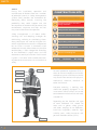
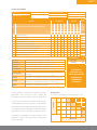
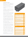
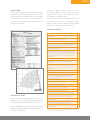
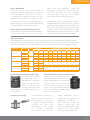
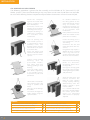
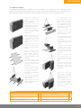
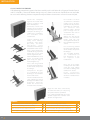
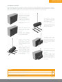
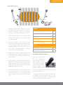
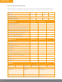
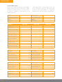
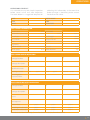
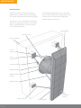
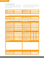
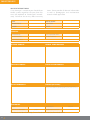
Installation, operation & maintenance manual Welcome to the FenderTeam Installation, Operation and Maintenance Manual. Fenders are safety-critical systems which protect people, the environment, ships and structures from harm. They need to perform on demand as the designer intended for their entire service life, even in the harshest locations. To do this fenders must be installed, used and maintained correctly. This Installation, Operation and Maintenance Manual provides guidance and tips for each stage but it cannot cover every possible scenario. This manual is intended to complement any local national or international rules and regulations, which must take precedence. At FenderTeam we want users to benefit from the high quality systems which have been supplied. Our specialists are on hand to guide or assist with all matters – your local FenderTeam office will be pleased to help. Fenderteam is a world-class designer and manufacturer of fenders and bollards. Our systems are used in ports, harbours and terminals around the world, and trusted by the largest and most respected consultants, contractors and operators. We want every FenderTeam product to give trouble-free service and optimum performance for many years to come. 2 > >> FENDER TEAM A team of experts, all dedicated to providing the best performing and most reliable fender systems and accessories. Headquartered in Germany and with local offices in France and the USA plus a network of well established local representatives, FenderTeam has earned a reputation as a reliable partner in the international port, harbour and waterways markets. Fender: we are specialists in the design, manufacture and sale of fenders and fender systems. Team: our team of partners, employees, reputable and approved suppliers all share one ethos – a passion for fenders and to serve the port industry. Collectively we have decades of experience and specialized knowledge in this niche market which is highly safety critical to people, ships and port infrastructure. Our skills and know-how ensure well engineered fender solutions, high quality products and fair prices. Contents CONTENTS SECTION 1 : SAFETY Risk Assessment 05 Unloading and Storage 06 Lifting 07 SECTION 2 : INSTALLATION Installation equipment 08 Setting out 09 Anchors 10 Grouts 10 Bolts 11 SPC Cone and CSS Cell Fenders 12 FE Element Fenders 13 V-Fenders and FE-V Fenders 14 Cylindrical Fenders 15 Foam Fenders 16 Donut Fenders 17 Pneumatic Fenders 18 Hydropneumatic Fenders 19 SECTION 3 : OPERATION Installation Acceptance Report 20 Operations Limits 22 Operations Checklist 23 SECTION 4 : MAINTENANCE Maintenance 25 Maintenance Checklist 26 Maintenance Inspection Periods 27 Incident Report Form 28 > 3 Safety SAFETY During the installation, operation and maintenance of fenders there are a number of potential hazards. A Safety Management System (SMS) provides the framework for identifying these hazards, assessing the probability they could happen and the consequences or outcome for personnel, the environment, structures and ships. An SMS may also include financial exposures. Safety management is all about understanding risks and adopting strategies for eliminating, reducing or monitoring them. Many techniques are used to mitigate risks which might otherwise result in unexpected loss or harm. A matrix is commonly used where each hazard, either alone or in possible combinations, is then categorised according to the likelihood it might occur and the outcome or severity of an event. Each hazard is given a “risk score” with suitable measures or procedures to minimise risk and maximise safety. CONSTRUCTION SITE Construction work in progress. Children and animals are not permitted on this construction site. Unauthorised entry to this site is strictly forbidden. Safety helmets must be worn. Protective footwear must be worn. High visibility clothing must be worn. Eye protection must be worn This is a no smoking site. No hat No boots No entry! Personal Protective Equipment Eye protection Hard hat Ear defenders High visibility coveralls Personal protective equipment (PPE) is worn to minimise exposure to serious workplace injuries and illnesses which may result from contact with physical, mechanical, chemical, electrical or other site hazards. Everyone entering a working area should be properly equipped. A risk assessment should always be carried out to determine the hazards and most suitable PPE. Gloves Depending on the location and type of work additional PPE should be worn such as gloves, safety glasses and shoes, earplugs or ear defenders, hard hats, respirators, coveralls, high visibility vests, safety harnesses and personal flotation devices (PFDs). Safety boots 4 > Safety Risk assessment 4 3 2 1 4 X X X X X X X X X X Outcomes for people, the environment and property should be considered separately and prioritized. 9 8 12 8 4 3 8 4 8 5 Very High Risk >10 High Risk 5–9 Low Risk 1–4 This table is available as an Excel spreadsheet template for FenderTeam customers. Risk Matrix A matrix is commonly used to assess risks. Severity Each hazard should be ranked according to its likelihood. Events may occur in isolation or combine to create another identifiable event. The judgement of likelihood could be based on experience, similar activities or other criteria. X X X X Catastrophic During fender installation, maintenance and operation, each activity or task should be considered and individual hazards identified. 1 X Death, system loss, or irreversible environmental damage Severe injury, occupational illness, major system damage, or reversible severe environmental damage Injury requiring medical attention, illness, system damage, or mitigatible environmental damage Possible minor injury, minor system damage, or minimal environmental damage Minor 2 X X X X an event likely to occur many times event expected to happen several times event that might happen at least once unlikely to happen but could at some time event highly unlikely to ever arise Critical 3 X Frequent Probable Occasional Remote Improbable Serious Minor 5 Catastrophic Score > Improbable Dropped objects Falling from height Falling into water Lifting objects with a crane Grinding and cutting steel Fires caused by welding or burning Collisions with plant or materials Structural or formwork collapse Crane collapse or toppling Slipping or tripping Remote 1 2 3 4 5 6 7 8 9 10 Risk Score Severity Occasional Key hazards associated with this activity/task Probable Ref Likelihood Frequent Hazards Critical Task/Activity: ABC123 Likelihood x Severity Risk Assessment Ref: Project No: Date Prepared: Serious Project Title: 4 4 8 12 16 20 3 3 6 9 12 15 2 2 4 6 8 10 1 1 2 3 4 5 1 2 3 4 5 Likelihood > 5 Safety Unloading AND STORAGE FenderTeam pack every shipment with the greatest care. Fender components are often transported in 20’ and 40’ containers. Open-top and flat rack containers may be used to make unloading easier. Any container parts that could obstruct the unloading of goods should be removed or rolled back. A level, clean and dry area of ground should be prepared in readiness to store the shipment after unloading. Locate all lifting points before beginning to move items, and remove any packing straps. Parts up to 2.1m across can be removed vertically from open-top containers. Parts between 2.1m and 2.3m in width will need to be extracted via the end opening after first removing any smaller parts in the way. Check the delivery matches the shipping documents and diagrams. Remove and recycle packing and support materials. Smaller parts and assemblies will usually be sent in closed containers. These can be easier to unstuff at the destination port or other nearby facility, then the goods sent by van to site (optionally a flatbed or open-top trailer for better access, on request). Store goods in a safe enclosure until they are needed. Use soft slings with lifting eyes for handling rubber and painted items. Check weights and centroids before lifting. Very large parts, above 2.3m across, are usually shipped on open flat rack containers which simplify access for lifting. Support goods on suitable bearers on dry, level ground. Avoid damage to paintwork. Check threads and sockets are clean and free from contaminants. Always use appropriate lifting equipment for each component, taking great care to protect any paintwork or vulnerable parts while lifting. Please inform FenderTeam immediately of any damage incurred in transit before goods are unloaded. The shipping insurer will require clear photographs and statements to determine liability and settle claims. 6 > ALWAYS NEVER In the rare event of serious damage to the cargo, the insurer may choose to send a surveyor to inspect and record the damage. Unpack before components are needed, except for visual check of quality and quantity on receipt. Minor coating damage due to transport, local handling or installation is normally the contractor’s responsibility to touch up, and should be carried out after installation, unless the affected areas will be submerged or hard to access. Risk damage by using unnecessary force. Move goods with unprotected lift forks or hooks. Drag components over the ground. If you are in any doubt or have further queries, please contact your FenderTeam office. Weld, grind, shot-blast or similar near the storage area or assembly site. Safety SAFE LIFTING Lifting and manoeuvring large fenders from the shore or from floating platforms is a safety critical operation. Where there are large tides or strong currents the lift must be carefully planned and executed to be completed in a short time window. Large lifts often require multiple cranes for stable support of large loads. In marine projects where access can be limited, many lifts require a large outreach. Suitable cranes must be selected with care to consider site access and ground conditions. Lifting capacity should be considered at pick-up, swing and set-down radius. Pre-lift checklist* Is the crane configured according to the lift plan? Has the crane been inspected and is its condition acceptable? Has the rigging equipment been inspected, secured, and is it in acceptable condition? Is the supporting surface stable? Are proper crane mats placed under outrigger floats and at a 90-degree angle to the outrigger cylinders? Are crawler cranes on proper crane mats? Are outriggers (if applicable) fully extended with tyres off the ground? Is the crane within 1° of level? Has the levelness of the crane been checked with a 1 metre or longer carpenter’s level or other acceptable method? The ‘target’ level in the crane cab can be used for initial leveling but should not be considered reliable for critical lifts. Is the exact fender weight known? Is the location of the center of gravity of the load known and the crane hook positioned directly above it? Was the load radius measured exactly? For heavy lifts, has the potential increasing load radius due to deflections in the boom, tyre, and/or carrier been considered? Was the boom length determined exactly? Was the boom angle determined exactly? Are wind conditions acceptable? Typically if wind speeds exceed 40kph (25mph), the lift should not be attempted. Ideally wind speeds should not exceed 20kph (12mph). Is the rope reeving balanced to prevent boom twist? Is the rigging capacity acceptable? Is the weight of the rigging known? Has the clearance between the boom and the load been considered and is it sufficient? Has the clearance between the boom tip and block been considered and is it sufficient? Is the crane operator experienced and qualified? Critical Lift Plan A lift plan should be prepared for every case, taking account of the worst combinations of lifting requirements and potential hazards. The assembled weight of the complete fender system should be checked on-site before the final lift is attempted. Has a qualified crane signal-person been assigned and a method of communication between the crane operator and signal-person established? Is someone assigned to control the load with the use of a tag line? Is the area clear of obstacles (including power lines, pipelines, and unnecessary personnel)? Has there been a pre-lift meeting between the crane operator, signal-person, supervisor, and other relevant people? *This sample checklist is provided for guidance only. A projectspecific checklist should always be prepared by the contractor responsible for fitting the fenders. > 7 Installation Installation equipment Always use the correct equipment for fender preparation and installation. This is important for safe working and avoids unnecessary damage to the fender. Lifting Chains or Slings Ensure the correct number, length and capacity of lifting chains or slings are available for each lift. Fork Protectors Avoid damage to rubber fenders and paintwork with fork protectors. Sockets and spanners Always use the correct size, purpose-made spanners and sockets. Flogging spanners can help when tightening large fixings. ALWAYS Use undamaged and certified lifting equipment Use soft slings with lifting eyes for handling rubber and painted items. Check weights and centroids before lifting. Use suitable shackles when lifting from padeyes. Use spreader beams to avoid excessive angles on slings or chains. Ensure that components are stable and cannot fall before removing slings. Check that ground conditions are firm enough for crane operations. NEVER 8 > Use makeshift tools that were not designed for the job. Use unnecessary force which may cause damage. Move goods with lift forks or hooks. Drag components over the ground. Weld, grind, shot-blast or similar near the storage area or assembly site. Prybars Use prybars with care to align fixing holes, or align parts using a centre-pin or dowel. Setting out New concrete structures use cast-in anchors to securely mount the rubber fender unit, chain brackets and other assemblies. Existing structures use retrofit anchors bonded into post-drilled holes. For all structures, it is essential to position the anchors correctly to match the hole locations on the fender assembly. It is also necessary to avoid interferences with obstacles such as reinforcement bars. Any electrical contact between anchors and reinforcement bars will form a galvanic cell when water is present and this can promote corrosion. Cast-in anchors should be electrically isolated from other permanently embedded steel in the structure. Retrofit anchors are usually insulated by the resin grout annulus. Installation Templates A template should be used to correctly locate anchor bolt positions in the structure. Templates are not intended to support the weight of anchors. Always refer to the general arrangement drawing when preparing a template. Template Hole Sizes The correct hole size should be used in templates. It is commmon to drill a smaller hole as a ‘pilot’ to identify the position of the anchor and guide the drill for the full-size hole. After the template is removed, the correct diameter hole can be drilled. In the past templates have been made on site from steel or plywood. Cast-in Anchors Most new concrete structures use cast-in anchors. These should be placed in the correct location and secured to prevent movement during concrete pours. A temporary bolt or stud is preferred for holding the cast-in anchor into formwork and avoids the permanent assembly bolt from being lost or damaged. Fender System Bolting Template Temporary stud, washer & nut Formwork M20–M72 Avoid electrical contact FenderTeam can also provide templates printed on plastic coated fabrics. These are dimensionally stable and can also be rolled or folded. They are light enough to send by post or courier. Nail Plates Nail plates are a simple and effective way to support cast-in anchors. The permanent bolt may need to be longer to allow for the recess caused by the nail plate’s thickness. Temporary plastic sealing caps can be used to protect the socket from ingress of dirt and debris before the final installation. Checklist “Measure twice, drill once”. Clean threads and sockets thoroughly. Avoid electrical contact between anchors and concrete reinforcements. Ensure anchors are straight and level. Check hole diameters and depths for retrofit anchors to avoid insufficient or excess grout. Avoid electrical contact between anchors and concrete reinforcements. > 9 Installation Retrofit Anchors Existing structures may require retrofit anchors. These are threaded studs which are bonded into drilled holes using high-strength resin grout. When damp conditions are expected, please inform FenderTeam so that the correct grout can be supplied. Not all grouts are suitable for installation in wet or damp locations. Typical Curing Time (Standard Grade¹) Always refer to the FenderTeam drawings to confirm details of hole depth and diameter, and for the size and quantity of grout capsules required per hole. Cartridge Grout Systems Cartridge grout systems are available in standard and express (fast cure) grades, in different cartridge sizes and in coaxial or standard tubes. Temperature of base concrete -5°C (min.) -4°C to -1°C 0°C to +4°C +5°C to +9°C +10°C to +19°C +20°C to +29°C +30°C to +34°C +35°C to +39°C +40°C (max.) Gel time Dry base Wet base 1h30 45 mins 20 mins 12 mins 6 mins 4 mins 2 mins 1.4 mins 1.4 mins 5h30 5h30 3h00 2h00 1h20 0h45 0h25 0h20 0h15 11h00² 11h00² 6h00 4h00 2h40 1h30 0h50 0h40 0h30 Typical Curing Time (Express Grade¹) Manual, pneumatic, electric and batteryp owered cartridge guns are available depending on the size of the job and grout volume per hole. 1 2 Temperature of base concrete -5°C (min.) -4°C to -1°C 0°C to +4°C +5°C to +9°C +10°C to +19°C +20°C to +29°C +30°C(max.) Gel time Dry base Wet base 40 mins 20 mins 10 mins 6 mins 3 mins 1 min 1 min 4h00 4h00 2h00 1h20 0h40 0h20 0h10 8h00 8h00 4h00 2h00 1h20 0h40 0h20 ¹Cartridge tempature should be at least +5°C. ²Ensure icing does not occur in the hole. Drill a perpendicular hole of the correct diameter and depth. Blow out debris. 3 Inject the correct volume of grout. Refer to manufacturer instructions on temperatures. 5 Allow the grout to cure. Refer to table for cure times at different temperatures. Clean the hole with a nylon brush and blow out any remaining debris. 4 Push and rotate the anchor stud into the hole. Clean any grout leakage immediately. 6 Fenders or brackets should only be connected after the grout is properly cured. Grouts will not cure if the temperature is too low, or they will cure too fast at high temperatures. The temperature of the concrete is also critical. 10 > Capsule Grout Systems (M30 max.) G l a s s g ro u t capsules are also available. There is minimal waste but the capsules are easily broken if mishandled. They are best suited to smaller anchors, up to M30 size. Please refer to FenderTeam if glass capsules are required for larger anchor sizes. ALWAYS Check and confirm the required grout volume for each anchor hole. Verify that the drilled hole depth and diameter is within tolerance. Check the inside temperature of the concrete and consider cure times. Support anchors centrally in the hole and prevent grout leakage with a seal. NEVER Use broken or damaged glass grout capsules. Use cartridges after grout has begun to cure. Install anchors when temperatures are too low for the grout to cure. Installation Bolt Tightening Fender fixing bolts and anchors should be tightened correctly. Too loose and they will undo, too tight and they may fail. There is no absolute bolt torque for every case. This depends on the material, surface finish, tolerances and lubrication. Elastic connections (ie. fender flanges) must be treated differently to rigid connections (ie. fender brackets). head) then the connection should be tightened snug tight until the fender head and panel are flush. Then use a flogging hammer to apply 1/8 to 1/4 turn to the bolt head. Apply Loctite medium (or equiv.) When fender flanges are being fixed, there is no defined torque. A special washer is used to spread the clamping forces in the rubber. The bolt should be tightened until the washer embeds 2–3mm into the rubber. Bolts should be re tightened by a quarter to half a turn after seven days to allow for rubber relaxation. Fender Flange & Embedded Connections When panels are fixed to embedded sockets/ inserts in the rubber (e.g. SPC / SX-P fender Rigid Connections The table below is for guidance only and assumes the nut or female thread are stronger than the bolt. High end friction values are assumed. If the friction is lower this may result in less preload than intended. Lubrication assumes that both the male and the female threads are thoroughly coated. Bolt class Lubrication Preload Dry Oiled Grade 4.6 MoS2 Dry Grade 8.8 Oiled MoS2 Dry A4-50 (SS316A) MoS2 Anti-galling Dry A4-70 (SS316SH) MoS2 0.6σy 0.6σy 0.6P0.2 0.6P0.2 Friction Thread Head 0.18 0.17 0.12 0.18 0.17 0.12 0.50 0.45 0.23 0.50 0.45 0.23 Thread Lubrication (Galvanised Fixings) Galvanised bolts should be lubricated with a Molybdenum Disulphide (MoS₂) grease or paste. Oiling is possible but this degrades the marine environment and makes future disma ntling difficult. Preventing loosening 0.18 0.17 0.12 0.18 0.17 0.12 0.50 0.35 0.12 0.50 0.35 0.12 M16 84 80 58 224 212 156 M20 Torque (Newton metres or Nm) M24 M30 M36 M42 M48 164 156 114 437 415 304 283 269 197 755 717 525 561 532 389 1496 1420 1037 979 929 678 2610 2476 1807 1565 1484 1082 4173 3958 2885 2348 2227 1621 6261 5938 4324 M56 3765 3570 2595 10041 9521 6921 Not recommended – maximum preload is only 0.3σy – refer to FenderTeam. 69 136 235 465 811 1297 1947 3124 Not recommended – maximum preload is only 0.3σy – refer to FenderTeam. 149 291 503 996 1739 2780 4172 6694 Thread Lubrication (Stainless Steel Fixings) Stainless steel can suffer galling or ‘cold welding’. Bolts lock and can no longer be tightened or dismantled. The old fixing must be cut out and a new one installed. Anti-gall paste is strongly recommended for stainless steel bolts. Copper based greases and others are unsuitable. A threadlocking adhesive is the best way to stop fixings from loosening in service. It is applied to threads before assembly and only cures anaerobically. Many grades are available depending on materials and environ- mental conditions, but a medium viscosity type such as Weiconlock® is preferred. Other methods include tab washers, locking pins and tack-welding bolt heads to the washers. For further advice please contact FenderTeam. > 11 Installation SPC CONE AND CSS CELL FENDERS The following procedure is generic for the assembly and installation of SPC Cone and CSS Cell fender systems. The actual fender design may vary from case to case. FenderTeam are available to assist with defining the best sequence and precautions to ensure a safe and successful job. Check the template against the fender bolt pattern, brackets and other bolted parts. Accurately locate the anchors on the structure according to the design. Template drawings or ready-to-use templates a re ava i l a b l e f ro m FenderTeam. Fit suitable shackles to the lifting points on the panel and connect a chain sling of suitable size. Component weights are indicated on the drawings or are available from FenderTeam. Place protective materials under the bottom of the panel where it rotates. Prior to placing the main fender system, it is suggested to install ancillary items like brackets. Chains may be connected to the panel or structure first. Clean out sockets and check all threads before offering up the fender system. Ensure the lifting area is clear and that it is safe to start lifting. Commence the lift and rotate the panel until it is vertical. Long panels may require a double lift using a second crane. Tag lines can be used to control the panel when it is near to vertical. Prepare a large enough working area to preassemble fenders, well away from any cutting, grinding or shot blasting. Place the fender panel face down, supporting it on suitable bearers to protect PE pads and paintwork. Lift the SPC or CSS fender into position with soft slings or eyebolts and hooks. Take care not to damage the rubber. Fit all bolts through the fender flange using the special washers. Make certain that all fixing points are accessible, particularly where there are large tides. Use tag lines to help guide the fender into position, avoiding damage to rubber and paintwork. Align the bolt holes and loosely assemble the bolts (or nuts). Tighten fixings equally, working diametrically until the washer embeds 2-3mm into the rubber. It is recommended that the crane should support the fender system until chains are connected and tensions are properly adjusted. ALWAYS Check anchor positions before fitting fenders Provide a safe working area for assembly Clean sockets and test fender bolts for fit Use the proper lifting equipment 12 > Use the correct fixings and washers Protect paintwork from damage during lifts Loosely assemble all bolts before tightening Tighten correctly for rigid or elastic connections Installation FE Element Fenders The following procedure is generic for the assembly and installation of FE element fender systems. The actual fender design may vary from case to case. FenderTeam are available to assist with defining the best sequence and precautions to ensure a safe and successful job. Check the template against the fender bolt pattern, brackets and other bolted parts. Accurately locate the anchors on the structure according to the design. Template drawings or ready-to-use templates a re ava i l a b l e f ro m FenderTeam. Prior to placing the main fender system, it is suggested to install ancillary items like brackets and support chains. Clean out sockets and check all threads before offering up the fender system. Prepare a large enough working area to preassemble fenders, well away from any cutting, grinding or shot blasting. Place the fender panel face down, supporting it on suitable bearers to protect PE pads and paintwork. Lift the FE elements into position with soft slings or eyebolts and hooks. Take care not to damage the rubber. Fit all bolts through the fender flange using the special washers. Tighten bolts until the washer embeds 2-3mm into the rubber. Fit suitable shackles to the lifting points on the panel and connect a chain sling of suitable size. Component weights are indicated on the drawings or are available from FenderTeam. Place protective materials under the bottom of the panel where it rotates. Ensure the lifting area is clear and that it is safe to start lifting. Commence the lift and rotate the panel until it is vertical. Long panels may require a double lift using a second crane. Tag lines can be used to control the panel when it is near to vertical. M a ke c e r t a i n t h at all fixing points are accessible, particularly where there are large tides. Use tag lines to help guide the fender into position, avoiding damage to rubber and paintwork. Align the bolt holes and loosely assemble all the bolts (or nuts). Tighten fixing equally on opposite sides. It is mandatory that the crane should support the fender system until chains are connected and adjusted. ALWAYS Check anchor positions before fitting fenders Provide a safe working area for assembly Clean sockets and test fender bolts for fit Use the proper lifting equipment Use the correct fixings and washers Protect paintwork from damage during lifts Loosely assemble all bolts before tightening Tighten correctly for rigid or elastic connections > 13 Installation SX, SX-P and FE-V Fenders The following procedure is generic for the assembly and installation for all types of FenderTeam V and FE-V fenders. The actual fender design may vary from case to case. FenderTeam are available to assist with defining the best sequence and precautions to ensure a safe and successful job. Check the template against the fender bolt pattern, brackets and other bolted parts. Accurately locate the anchors on the structure according to the design. Template drawings or ready-to-use templates a re ava i l a b l e f ro m FenderTeam. Prepare a working area away from cutting , grinding and other possibly harmful operations. Place V-fenders on their flanges and allow them to recover from small distortions induced during shipment which will assist with anchor alignment later. Mount UHMW-PE or steel panel to Fender head (SX-P only) See page 11 for bolt tightenery. Pass a soft sling around the front and inside faces of the fender, away from the flanges. Component weights are indicated on the drawings or are available from FenderTeam. Lift the V-fender from the sling, taking care not to damage the rubber. Place protective materials under the end of the V-fender where it rotates. FE-V fenders are best assembled in a wooden cradle. The PE shield is placed centrally and the individual FE elements are lowered into position. Bolts should pass through the PE shield with the nut on the element side. Always use the correct washers to distribute loads and do not over-tighten the bolts as this could damage the PE shield. Pass a soft sling around the front and inside faces of the fender, away from the flanges. The assembly weights are indicated on the drawings or are on request from FenderTeam. Raise the FE-V fender carefully from the cradle using the sling, taking care not to damage the rubber or PE shield. Place protective materials under the end of the FE-V fender where it rotates. Align the bolt holes and loosely assemble the bolts (or nuts) using the special washers provided. It is recommended that the crane should support the V-fender until all bolts are tightened. ALWAYS Check anchor positions before fitting fenders Provide a safe working area for assembly Clean sockets and test fender bolts for fit Use the proper lifting equipment 14 > Use the correct fixings and washers Protect paintwork from damage during lifts Loosely assemble all bolts before tightening Tighten correctly for rigid or elastic connections Installation Cylindrical Fenders The following procedure is generic for the assembly and installation of Cylindrical Fender systems. The actual fender design may vary from case to case. FenderTeam are available to assist with defining the best sequence and precautions to ensure a safe and successful job. Accurately locate the anchors on the structure according to the layout on the GA drawing. Template drawings or ready-to-use templates are available as an option on request from FenderTeam. Component weights are indicated on the drawings or are available from FenderTeam. Lift the cylindrical fender assembly by the sling, taking care not to damage the rubber. Clean out sockets and check all threads before offering up the fender brackets. Install the suppor t brackets prior to placing the cylindrical fender. Prepare a large enough working area to preassemble fenders, well away from any cutting, grinding or shot blasting. Place the fender on bearers and pass a soft sling through the bore. Very long fenders may require a spreader beam. Pass the support chain, bar or bracket through the fender bore. To allow slack in the supporting chains, offer the cylindrical fender up to the berth face higher than its final mounted position. Connect the shackle to the support brackets, not forgetting to insert the split pins. Slowly lower the cylindrical fender until its chains are tight. Check that the chain angle is equal on both sides of the fender. ALWAYS Chock cylindrical fenders during storage to prevent rolling. Fill voids in sheet pile impans to create a flat surface. Provide uplift chains if the fenders could roll up the dock face with rising tides or a reducing ship draft. Use a spreader bar or beam for long fenders. > 15 Installation Foam Fenders The following procedure is generic for the assembly and installation for OceanGuard fender systems. FenderTeam are available to assist with defining the best sequence and precautions to ensure a safe and successful job. Check the template against the fender bolt pattern, brackets and other bolted parts. Accurately locate the anchors on the structure according to the design. Template drawings or ready-to-use templates a re ava i l a b l e f ro m FenderTeam. Clean out sockets and check all threads before offering up the fender brackets. Install the suppor t brackets prior to placing the fender system. Prepare a large enough working area to handle and prepare the fenders, well away from any cutting, grinding or shot blasting. Support the fender on bearers. Connect all support chains to the end termination shackles. It is useful to identify each chain if the system has more than one chain at each end. Fender weights are indicated on the drawings or are available from FenderTeam. Lift the OceanGuard fender assembly by the sling, taking care not to damage the skin. A spreader bar or beam is recommended for long fenders. To allow slack in the supporting chains, offer the OceanGuard fender up to the berth face higher than its final mounted position to ensure there is some slack in the primary weight support chains. Connect the weight support chains to the support brackets and insert the split pins into the shackles. Large chains are heavy and may require extra cranage to assist connection. Lower the OceanGuard fender and check that the chain angle is equal on both sides. When the fender is correctly positioned, connect any additional chains. ALWAYS Chock OceanGuard fenders during storage to prevent rolling. Fill voids in sheet pile impans to create a flat surface. Install protective strips or facings over abrasive dock surfaces to reduce fender wear. Consider adding ballast (chains, weights, etc.) on floating installations to dampen fender motion. Consider asymmetric chain lengths to maintain fender position if long mooring chains are used. 16 > Installation Donut Fenders The following procedure is generic for the assembly and installation for all types of FenderTeam Donut fenders. The actual fender design may vary from case to case. FenderTeam are available to assist with defining the best sequence and precautions to ensure a safe and successful job. Prepare a large enough working area to handle and prepare the fenders, well away from cutting, grinding or shot blasting. Suppor t the Donut fender on bearers and use chocks to prevent rolling. Spirally Welded Piles When spirally welded piles are used for Donut fenders, the external weld should be ground flat in the area contacted by the Donut bearings from the lowest to highest tide levels. Protruding welds may increase wear on the bearings and, in some cases, can cause the Donut to seize on the pile. Use a suitable spreader bar or long leg sling to ensure chains or strops clear the pile during installation. Fender weights are indicated on the drawings or are available from FenderTeam. Lift the Donut fender using the sling, taking care not to damage paintwork or the skin. Ensure the Donut fender is hanging vertically before lowering onto the pile. Use a tag line to guide the Donut tube over the pile, checking to ensure bearings do not snag on the end of the pile. Continue lowering until the Donut floats and the sling can be safely removed. After installation, check the Donut fender is free to rotate, rise and fall with the tide. ALWAYS Chock the Donut fender when stored. Grind welds flush on the piling exterior. Guide the fender bearings over the piles to avoid snagging. > 17 Installation Pneumatic Fenders Request a full instruction manual for pneumatic fenders from FenderTeam. The process is simple if these basic rules are followed: 1 2 3 1. Release the straps which hold the fender onto the pallet or skid. 2. Unroll the fender so it is free to inflate. 3. Use fork protectors when moving the fender. 4. Keep chocks available to stop the fender rolling as it inflates. 5. Ensure the compressor has a dryer – don’t fill the fender with moist air. 6. Only lift from the lifting points or from the chain and tyre net. 7. Avoid contact with sharp edges. 4 5 Small and medium fender sizes (≤ ∅2.5m) 6 7 Large fender sizes (> ∅2.5m) 6 2 4 4 3 7 1 5 1. Small inflation valve 2. Valve cap 3. Pressure gauge 4.Small hose connector 5. Air hose to compressor 6.Pressure check valve 7. Large inflation valve 8.Air control valve 18 > 3 5 3 8 5 Large fenders are fitted with overpressure safety valves, which can be at either end of the fender. Over-inflation of pneumatic fenders is dangerous. Always use an accurate gauge with the correct scale, confirm the required inflation pressure and monitor continuously during inflation. Car tyre gauges are not suitable for pneumatic fenders. Installation Fender Mooring Tips 4 2 5 1 W W 6 1. Sling-type pneumatics are light and can be affected by rough weather and waves. Oversize mooring chains can dampen motions, or add ballast weights to chains. 3 ALWAYS Leave some chain slack to allow for tides Operate the fender at the correct pressure 2. Only connect chains to the fender end fittings, never to the chain net or other part of the fender. Check for sharp edges that could damage the fender body Ensure at least two fenders are in contact with the moored ship. 3. Constant motions cause vibrations and shackles or other parts may come loose. These should be effectively secured using suitable split pins, tie wires, locking nuts, tack welds or threadlocking adhesive (see p11) to prevent loosening. Inflate the fender with dry air. 4.Where the structure could abrade the fender body then it should be fitted with PE pads or timber rubbing strips to reduce wear and tear. 5. Where mooring chains contact the corner edge of a structure, rubber tubes should be fitted around the chains to prevent them from abrading the concrete and to help protect the galvanised finish. 6.To reduce sideways drift of fenders with long mooring chains at high tides (when the mooring chains are slack), make one chain longer or add some ballast to one side. NEVER Allow the fender to ‘walk’ up the berth and onto the top of structure. Permit excessive fender motion, which may cause ‘snatch’ in moorings. Hydropneumatic Fenders Please ask FenderTeam for the Hydropneumatic fender instructions before inflating the fender or deployment. Hydropneumatic fenders require some special techniques to install, add the ballast weight and to trim the fender to the correct draft by water filling. The performance of Hydropneumatic fenders is affected by the air:water ratio and the initial pressure. FenderTeam can provide site training and supervision on request. > 19 Operations Installation acceptance report When installation is complete, FenderTeam require an Installation Acceptance Report (IAR) to initiate the warranty period. Failure to provide an IAR may invalidate or delay warranty claims. Project Ref: Location: Fenders Number: Type: Starts: Ends: Delivery Date Warranty Period Inspection of Contractor FenderTeam Contractor FenderTeam Setting out dimensions Fender spacing Fixings correctly installed and tightened Droop and sag of fenders within limits Fender positions, serial numbers recorded Face pads and fixings undamaged All paint damage touched up Spare parts inventory checked Snagging list Damage noted to: Rubber Steel fabrications Paintwork PE Pads Brackets Chains and accessories Anchors, bolts and other fixings Actions Responsibility Timeline Sign-off Contractor: Vendor: FenderTeam Name Name Name Signature Signature Signature Date Date Date Download this form from http://www.fenderteam.com/en/downloads.html 20 > Operations Ports should have clear operating practices and procedures. This is especially important for the safety-critical berthing, mooring and departure process. It is vital that all berth users are made aware of the performance limits of fenders and operate safely within these. Safe practices and procedures should be developed for each port and, where applicable, for each berth or terminal within the port. With respect to fenders this should include: Identifying hazard(s) to personnel, vessels and port structures; The likelihood of a hazard arising; Reviewing the consequences and outcome should an identified hazard occur; Preparing a risk analysis; Mitigating these risks where possible; Ongoing training of all personnel who are unavoidably exposed to any degree of risk; Regular operational reviews to identify new or changing risks. Fenders need to perform faultlessly when called upon to protect a port structure. ALWAYS Make a visual check of fenders before a ship arrives at the berth Check that the arriving ship is within the design limits of the fender Ensure that the Master and pilot are aware of safe berthing speeds and angles Make provision for escalating events such as deteriorating weather Monitor fenders and moorings regularly whilst a ship is on the berth NEVER Allow mooring lines or hull protrusions to snag on fenders Allow ships to berth on damaged or worn out fenders Permit non-essential personnel near fenders during berthing > 21 Operations OperationAL Limits Fender and mooring operating parameters should be available to all berth users: pilots, linesmen, Harbour Masters, arriving vessels and others involved in the berthing and mooring process. PORT These parameters should identify the safe limits of fenders, bollards and other dock furniture. The table below is a suggested template for summarising this information. BERTH NAME HARBOUR MASTER Tel: Port Operations Tel: Tugs Tel: Pilots Tel: VTS/VTIS Tel: Linesmen Tel: Vessels Min. Ship Max. Ship Other ship Type/class Deadweight Displacement (tonne) Length overall (metres) Breadth (metres) Laden draft (metres) Air draft (metres) Bow flare (degrees) Beltings Special features Berthing speed (m/s) Berthing angle (deg.) Draft limited approach Tide (min) m CD Tide (max) m CD Deck level m CD Dredged depth m CD Berth direction deg Berth construction * Maximum current knots Current direction Berthing wind speed knots Operating wind speed knots Cease operation wind knots Depart berth knots deg * open / semi-open / closed Fender type Fender model Rubber grade Fender spacing Fender projection metres Fender drawing no. Hull pressure kN/m² Reaction force Bollard type Bollard SWL Maximum line angle > kN Bollard model tonne Bollard spacing deg Bollard drawing no. Download this form from http://www.fenderteam.com/en/downloads.html 22 metres metres Operations Operations Checklist It is advisable to carry out a berth inspection before vessel arrival and after departure. The table below is a suggested template for collecting this information. In the event that fender damage is identified, please contact FenderTeam for advice. PORT BERTH NAME Date Time Name Signature Pre-arrival Information Vessel name Dimensions (L × B × D) m CD Vessel IMO Lmetres Bmetres Dmetres Vessel type Deadweight Arrival draft metres Arrival air draft Pilot Tug names tonne metres Master (1) (2) Tide on arrival (3) metres Current Wind speed knots knots Wind direction deg Pre-arrival Berth Inspection Damage location (1) (2) (3) Pilotyes/no Vesselyes/no Linesmenyes/no (2) (3) Damage description Identified hazards Warnings issued Risk mitigation measures taken Post-departure Berth Inspection Damage location (1) Damage description Cause Consequence Photos taken yes/no yes/no yes/no Vessel/agent informed yes/no yes/no yes/no FenderTeam informed yes/no yes/no yes/no Download this form from http://www.fenderteam.com/en/downloads.html > 23 Maintenance Maintenance When maintaining a fender system it is important to use the correct terminology. This avoids confusion when ordering spares. All moulded rubber fender units and steel panels are identified with a job specific serial number. These should also be identified when ordering spare parts. The full parts list is provided on the fender general arrangement drawing. Please refer to this if possible when discussing spare parts with FenderTeam. Top chamfer Tension chain Quay structure Chain anchor Chain bracket Chain tensioner Rubber fender Rubber fender anchor Weight chain Shear chain 24 > UHMW-PE facing Fender panel Maintenance The reasons for preventative maintenance: 1. Safety and reduced risks 2. Early identification of damage 3. Reduced operational costs 4. Less berth disruption 5. Warranty remains valid 6. Fewer claims and less aggravation 7. Extended service life Asset management is a systematic process of operating, maintaining, upgrading, and disposing of assets cost-effectively in a manner which benefits all users by adopting a long term philosophy. The foundations of an asset management system are defined in ISO 55000. The goal of any maintenance programme is to avoid or reduce the consequences of failure of equipment whilst maintaining safety at all times and achieving this at the lowest cost. This can be achieved by preventing a failure before it occurs with planned inspections and replacements. By routinely recording equipment wear and tear it is possible to replace or repair worn components before they cause a system failure. An ideal preventive maintenance program would ensure zero downtime. Well maintained fenders will remain safe, last longer and cost far less than the disruption caused by loss of use or claims following a breakage. > 25 Maintenance Maintenance Checklist It is advisable to prepare a checklist for routine preventative maintenance. The table below is a suggested template for collecting this information. In the event that fender damage is identified during a maintenance inspection, please contact FenderTeam for advice. PORT BERTH NAME Date Time Name Signature General Fender location Last inspection date General condition Excellent / Good / Average / Poor / Very Poor Rubber Fender Panel Ozone cracks yes/no Fixings tight, secure yes/no(photos) Dents, bends Cuts or abrasions yes/no Spillages (paint, oil) (photos, size) Paint condition, damage yes/no(photos) yes/no(photos) (photos, size) Brackets none/minor/major Corrosion, scratches Marine growth yes/no (vents blocked?) Welds, cracks Tidal operations yes/no (hydraulic locking?) Accident damage UHMW-PE face pads Chains Original thickness Weight/tension/shear Current thickness Slack yes/no(photos) yes/no(photos) yes/no(photos) W T S yes/no yes/no yes/no Evenly worn yes/no(photos) Diameter loss yes/no yes/no yes/no Cuts, gouges yes/no(photos) Shackle or link wear yes/no yes/no yes/no Missing pads yes/no(photos) Bracket damage yes/no yes/no yes/no Fixings loose, missing yes/no(photos) Split pins fitted yes/no yes/no yes/no Comments Photos (file names) Follow-up Refer to FenderTeam Date referred yes/no Warranty issue FenderTeam contact Download this form from http://www.fenderteam.com/en/downloads.html 26 > yes/no Maintenance Maintenance INSPECTION PERIODS An inspection and maintenance programme is needed to identify maintenance, wear and damage as well as the likely causes at an early stage. Three levels of inspection and maintenance are recommended. The table gives average periods for temperate climates. These should be more often in harsh environments such as the tropics. If you are uncertain about any aspect of inspection or maintenance, please consult FenderTeam. LEVEL 1 LEVEL 2 LEVEL 3 Close visual inspection Interim maintenance Major maintenance or overhaul Notes Rubber fenders Every year 4–6 years 15–25 years 1, 2, 8 Steel panels (frames) Every year 4–6 years 15–25 years 1, 3, 8, 9 Other fender steelwork Every year 4–6 years 15–25 years 1, 3, 8, 9 Corrosion protection systems Every year 4–6 years 10–15 years 1, 3, 8, 9 UHMW-PE face pads Every year 15–25 years 1, 4, 8 Anchors & bolts Every year 4–6 years 15–25 years 1, 5, 8 Chain, shackles & adjusters Every year 2–4 years 5–10 years 1, 6, 8 Every month N/A N/A 7 Valves and end fittings Every six months 4–6 years 5–10 years 10, 11 Marine growth Every six months 1–2 years N/A 12 INSPECTION AND MAINTENANCE PROGRAMME Initial pressure (pneumatic fenders) Notes 1. A close inspection should also be made after any incident which may have damaged the fenders or supporting structure. Always record the event, cause and consequences immediately. Where there is clear damage this should be reported to FenderTeam immediately using the form on page 28. 2. Interim maintenance will include, but is not limited to, the repair of any cuts and surface damage to the rubber. Paint spills should be removed by water jetting. Accident damaged rubber units with deep cuts or clear signs of overload should be immediately replaced. Please consult FenderTeam for advice. 3. Interim maintenance will include touching up of paintwork where underlying steel or primer is exposed according to paint manufacturers’ instructions. Close attention should be paid to edges where ropes may abrade, also around chain brackets. Bird droppings can aggressively attack paint and, if this is an ongoing issue, bird spikes or similar should be fitted. Repairs to dents and other minor damage should be carried out with careful attention paid to cause and possible loss of strength as a result. 4. Interim maintenance will include replacement of worn UHMW-PE pads, in particular all pads with remaining wear allowance insufficient to last until the next scheduled maintenance. Close attention should be given to cuts and heavy localised wear, often caused by inappropriate or poorly maintained ships. Pad fixings should be renewed when new pads are fitted, taking care to use the correct size and material grade of bolts, nuts and washers. 5. Interim maintenance will include retightening of loose bolts and anchors. Any missing locknuts, locking tabs or split pins should be replaced at the same time. The correct preload should be applied to fixings. The effects of surface corrosion on friction and bolt torques should be considered. If in doubt then consult FenderTeam for advice. 6. Interim maintenance will includes measurement of chain link and shackle diameter, particularly in the inter-tidal zone. Reference should be made to design corrosion allowances. Components must be changed if diameter is likely to reduce below permitted minimum before the next scheduled maintenance. Special attention should be given to “weak” links, where fitted, as these are smaller diameter and must protect other parts of the chain system from damage in the event of overloads. 7. The initial inflation pressure of pneumatics should be monitored and adjusted every month. If pressure drops gradually or unexpectedly this can indicate a leaking valve or small puncture which should be replaced or repaired immediately. Please consult FenderTeam for detailed procedures. 8. Full maintenance should be carried out when paint coatings, corrosion or damage demand removal of the fender systems for a more thorough overhaul. The opportunity should be used to dismantle the fender system, replace worn components, repair damage, and to shot blast and repaint all steelwork. Special attention should be paid to the rubber fender units, in particular any signs of ozone cracking. Overhauls also provide the opportunity to rotate fenders on the berth, moving heavily used systems to areas which are less used and vice versa. Please consult FenderTeam for advice on major maintenance and overhaul to confirm spare parts availability and the optimum scope of works. A FenderTeam engineer will visit site if required. 9. Most design specifications do not include corrosion allowances. Therefore the deterioration of pain or galvanising coatings will inevitably increase steel stresses. 10.Interim maintenance should include the replacement of the inflation valve and cap. This can usually be done in-situ with the appropriate tool and without first deflating the fender. 11. Major maintenance of pneumatic fenders includes dismantling of the end fittings, valves and replacing these components. Chain and tyre nets should also be overhauled or replaced. 12.Marine growth can hide or even cause maintenance issues. In areas prone to heavy marine growth and strong currents or tides, marine growth can increase drag forces or substantially increase the air weight of the fender system. Always remove heavy growth for inspection. Also make full allowance for increased fender weight due to marine growth when lifting out for major maintenance. > 27 Maintenance Incident Report Form If any damage is caused to your FenderTeam fender system, regardless of cause, then this must be reported to FenderTeam immediately. Failure to do so may affect warranty terms. Please provide all relevant information as well as photographs and maintenance records where applicable. PORT BERTH NAME Reported by Position Phone email General Incident date Last inspection date Fender location Fender number Suspected cause Rubber Damage Fender Panel Damage Face Pad Damage Chain system Damage Other Comments Photos (file names) Please take overview and close-up photos, submit in high resolution where possible. Indicate the file name(s) and respective fender position(s) Follow-up Client Sent to FenderTeam FenderTeam yes/no FenderTeam contact Download this form from http://www.fenderteam.com/en/downloads.html 28 > call/visit Maintenance AFTER SALES & WARRANTY FenderTeam are committed to providing support and assistance during commissioning and long into the future. We offer standard and extended warranties as well as guidance on inspection and maintenance programs to ensure our fender systems always provide the best performance and protection. The standard warranty period is 12 months from installation or 18 months form shipping date, although longer warranties are available on request. Performance guarantees are available if the option of fender performance testing is carried out. Extended paint warranties can also be provided. In all cases the warranties given are subject to berth operators conducting periodic inspections in accordance with FenderTeam recommendations, and the timely submission of reports and photographs. This allows any issues arising to be detected early, rectified and monitored. Warranties do not cover accidental damage, normal wear and tear, visual appearance or the effects of environmental degradation over time. In the unlikely event of a valid claim for faulty materials and/or workmanship, FenderTeam will repair or replace the defective components. Compensation values cannot exceed the cost of supplied materials, less any reduction for normal use, and in no circumstances are costs of removal or reinstallation, or any consequential costs or losses accepted. It is recommended that users adopt an asset management system based on ISO 55000 ( or PAS-55). DISCLAIMER Every effort has been made to ensure that the technical specifications, product descriptions and design methods are correct and represent current best practice. FenderTeam AG, subsidiaries, agents and associates do not accept the responsibility or liability for any errors and omissions for any reason whatsoever reason. When using this technical manual to develop a design, customers are strongly recommended to request a detailed specification, calculations and certified drawings from FenderTeam specialists prior to construction and/or manufacture. FenderTeam constantly strives to improve the quality and performance of products and systems. We reserve the right to change specification without prior notice. All dimensions, material properties and performance values quoted are subject to normal production tolerances. This manual supersedes the information provided in all previous editions. It should also be used in conjunction with current FenderTeam product catalogues. If in doubt, please consult FenderTeam. Flag: © 2015 FenderTeam AG, Germany This manual is the copyright of FenderTeam AG and may not be reproduced, copied or distributed to third parties without the prior consent of FenderTeam in each case. FenderTeam® is a Registered Trade Mark of FenderTeam AG. Date: 03 / 2015Version: IOM_Manual_EN_02 > 29 notes Notes 30 > notes Notes > 31 FENDER TEAM - GERMANY FENDER TEAM - FRANCE FENDER TEAM - AMERICAS FenderTeam AG FenderTeam France SAS FenderTeam Americas Inc. Tarpen 40, Haus 1 b 94 Av. Albert 1er 44084 Riverside Parkway, Suite 170 22419 Hamburg, Germany 92500 Rueil-Malmaison, France Lansdowne, VA 20176, USA Tel. + 49 (0) 40 20 90 764 70 Tel. + 33 (0)1 41 29 09 20 Tel. +1 (571) 281 37 70 Fax + 49 (0) 40 20 90 764 80 Fax + 33 (0)1 41 29 09 27 Fax +1 (571) 223 32 67 E-mail: [email protected] E-mail: [email protected] E-mail: [email protected] Web: www.fenderteam.com Web: www.fenderteam.com Web: www.fenderteam.com Presented by: www.fenderteam.com