1
Device for plant monitoring
232USPB-NR
Installation Manual
232USPB-NR-eng-IUS113210 | 98-0047010 | Version 1.0
CA
US
SMA America, LLC
Legal Restrictions
Copyright © 2011 SMA America, LLC. All rights reserved.
No part of this document may be reproduced, stored in a retrieval system, or transmitted, in any form
or by any means, electronic, mechanical, photographic, magnetic or otherwise, without the prior
written permission of SMA America, LLC.
Neither SMA America, LLC nor SMA Solar Technology Canada Inc. makes representations, express
or implied, with respect to this documentation or any of the equipment and/or software it may
describe, including (with no limitation) any implied warranties of utility, merchantability, or fitness for
any particular purpose. All such warranties are expressly disclaimed. Neither SMA America, LLC nor
its distributors or dealers nor SMA Solar Technology Canada Inc. nor its distributors or dealers shall
be liable for any indirect, incidental, or consequential damages under any circumstances.
(The exclusion of implied warranties may not apply in all cases under some statutes, and thus the
above exclusion may not apply.)
Specifications are subject to change without notice. Every attempt has been made to make this
document complete, accurate and up-to-date. Readers are cautioned, however, that
SMA America, LLC and SMA Solar Technology Canada Inc. reserve the right to make changes
without notice and shall not be responsible for any damages, including indirect, incidental or
consequential damages, caused by reliance on the material presented, including, but not limited to,
omissions, typographical errors, arithmetical errors or listing errors in the content material.
All trademarks are recognized even if these are not marked separately. Missing designations do not
mean that a product or brand is not a registered trademark.
The Bluetooth® word mark and logos are registered trademarks owned by Bluetooth SIG, Inc. and
any use of such marks by SMA America, LLC and SMA Solar Technology Canada Inc. is under
license.
SMA America, LLC
3801 N. Havana Street
Denver, CO 80239 U.S.A.
SMA Solar Technology Canada Inc.
2425 Matheson Blvd. E
8th Floor
Mississauga, ON L4W 5K5
Canada
Installation Manual
232USPB-NR-eng-IUS113210
3
Important Safety Instructions
SMA America, LLC
IMPORTANT SAFETY INSTRUCTIONS
SAVE THESE INSTRUCTIONS
This manual contains important instructions for the following products:
• 232USPB-NR
This manual must be followed during installation and maintenance.
The product is designed and tested according to international safety requirements, but as with all
electrical and electronic equipment, certain precautions must be observed when installing and/or
operating the product. To reduce the risk of personal injury and to ensure the safe installation and
operation of the product, you must carefully read and follow all instructions, cautions and warnings
in this manual.
Warnings in this document
A warning describes a hazard to equipment or personnel. It calls attention to a procedure or practice,
which, if not correctly performed or adhered to, could result in damage to or destruction of part or all
of the SMA equipment and/or other equipment connected to the SMA equipment or personal injury.
DANGER indicates a hazardous situation which, if not avoided, will result in death or serious injury.
WARNING indicates a hazardous situation which, if not avoided, could result in death or serious
injury.
CAUTION indicates a hazardous situation which, if not avoided, could result in minor or moderate
injury.
NOTICE is used to address practices not related to personal injury.
4
232USPB-NR-eng-IUS113210
Installation Manual
SMA America, LLC
Important Safety Instructions
Other Symbols in this document
In addition to the safety and hazard symbols described on the previous pages, the following symbol
is also used in this manual:
Information
This symbol accompanies notes that call attention to supplementary information that you must
know and use to ensure optimal operation of the system.
General Warnings
General Warnings
All electrical installations must be done in accordance with the local and National Electrical Code®
ANSI/NFPA 70 or the Canadian Electrical Code® CSA C22.1. This document does not and is not
intended to replace any local, state, provincial, federal or national laws, regulation or codes
applicable to the installation and use of the product, including without limitation applicable
electrical safety codes. All installations must conform with the laws, regulations, codes and
standards applicable in the jurisdiction of installation. SMA assumes no responsibility for the
compliance or noncompliance with such laws or codes in connection with the installation of the
product.
The product contains no user-serviceable parts except for the fans on the bottom of the enclosure
and the filters behind the fans as well as the handle covers on the sides of the unit. For all repair and
maintenance, always return the unit to an authorized SMA Service Center.
Before installing or using the product, read all of the instructions, cautions, and warnings in this
manual.
Before connecting the product to the electrical utility grid, contact the local utility company. This
connection must be made only by qualified personnel.
Wiring of the product must be made by qualified personnel only.
Installation Manual
232USPB-NR-eng-IUS113210
5
General Warnings
6
232USPB-NR-eng-IUS113210
SMA America, LLC
Installation Manual
SMA America, LLC
Table of Contents
Table of Contents
1
Information on this Manual. . . . . . . . . . . . . . . . . . . . . . . . . 9
2
2.1
2.2
2.3
Safety . . . . . . . . . . . . . . . . . . . . . . . . . . . . . . . . . . . . . . . . . 10
Intended Use. . . . . . . . . . . . . . . . . . . . . . . . . . . . . . . . . . . . . . . 10
Target Group Qualification . . . . . . . . . . . . . . . . . . . . . . . . . . . 10
Safety Instructions . . . . . . . . . . . . . . . . . . . . . . . . . . . . . . . . . . . 11
3
Product Description . . . . . . . . . . . . . . . . . . . . . . . . . . . . . . 12
4
Scope of Delivery . . . . . . . . . . . . . . . . . . . . . . . . . . . . . . . . 13
5
5.1
5.2
5.3
5.4
5.5
Electrical Connection . . . . . . . . . . . . . . . . . . . . . . . . . . . . . 14
Slot and Cable Route . . . . . . . . . . . . . . . . . . . . . . . . . . . . . . . . 14
Installing the Communication Interface . . . . . . . . . . . . . . . . . . . 17
Preparing the Enclosure Opening on the Inverter . . . . . . . . . . . 18
Installing a Communication Cable in the Inverter . . . . . . . . . . . 19
Connecting the Cable to the Communication Interface . . . . . . 21
6
6.1
6.2
Decommissioning . . . . . . . . . . . . . . . . . . . . . . . . . . . . . . . . 22
Disassembly . . . . . . . . . . . . . . . . . . . . . . . . . . . . . . . . . . . . . . . 22
Disposal . . . . . . . . . . . . . . . . . . . . . . . . . . . . . . . . . . . . . . . . . . 22
7
Technical Data . . . . . . . . . . . . . . . . . . . . . . . . . . . . . . . . . . 23
8
FCC Compliance Information . . . . . . . . . . . . . . . . . . . . . . 24
9
Contact . . . . . . . . . . . . . . . . . . . . . . . . . . . . . . . . . . . . . . . . 25
Installation Manual
232USPB-NR-eng-IUS113210
7
Table of Contents
8
232USPB-NR-eng-IUS113210
SMA America, LLC
Installation Manual
SMA America, LLC
1
1 Information on this Manual
Information on this Manual
Validity
This manual is valid for the communication interface "232USPB-NR".
This manual does not contain any detailed information about the connected devices. Detailed
information about the connected devices is provided in the manuals for the devices.
Target group
This manual is intended for skilled workers. Only qualified personnel is allowed to perform the tasks
set forth in this manual (see section 2.2 "Target Group Qualification", page 10).
Nomenclature
In this manual, the 232USPB-NR is referred to as communication interface.
SMA America Production, LLC and SMA Solar Technology Canada Inc. are hereinafter referred to
as SMA.
Abbreviations
Abbreviation
Description
Explanation
AC
Alternating Current
Alternating current
DC
Direct Current
Direct current
Installation Manual
232USPB-NR-eng-IUS113210
9
2 Safety
2
SMA America, LLC
Safety
2.1 Intended Use
The 232USPB-NR is a communication interface connecting an inverter with other communication
products by wires.
The following inverters will be supported:
• SB/WB 700-U
• SB/WB 5000-US
• SB/WB 1100-U
• SB/WB 6000-US
• SWR 1800-U
• SB/WB 7000-US
• SWR 2100-U
• SB/WB 8000-US
• SWR 2500-U
• SB 6000-U
• SB/WB 3000-US
• SB 3300-U
• SB 3800-U
• SB 4000-US
Only use the communication interface in accordance with the information provided in the enclosed
documentation. Any other use can result in personal injury or property damage.
The enclosed documentation is part of this product.
• Read and observe the documentation.
• Keep the documentation in a convenient place for future reference.
2.2 Target Group Qualification
Skilled workers have received training and have demonstrated skills and knowledge in the
construction and operation of this device. Skilled workers are trained to deal with the dangers and
hazards involved in installing electrical installations.
10
232USPB-NR-eng-IUS113210
Installation Manual
SMA America, LLC
2 Safety
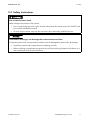
2.3 Safety Instructions
Risk of lethal electric shock
Lethal voltages are present in the inverter.
• Prior to performing any work on the inverter, disconnect the inverter on the AC and DC side
(see inverter installation manual).
• All work on the inverter may only be carried out by a electrically qualified person.
Electrostatic discharges can damage the communication interface
Component parts of the communication interface can be damaged by electrostatic discharges.
• Avoid any contact with component parts and plug contacts.
• Before touching a component part ground yourself by touching a protective conductor or a
non-coated part of the inverter enclosure.
Installation Manual
232USPB-NR-eng-IUS113210
11
3 Product Description
3
SMA America, LLC
Product Description
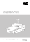
The 232USPB-NR is a communication interface connecting an inverter with other communication
products by wires.
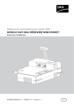
Figure 1:
RS232 communication interface
Position
Designation
A
Pin row, short
B
Pin row, long
You can connect the inverter to the serial interface of a PC by means of the communication interface
and a communication cable with DE9 plug.
12
232USPB-NR-eng-IUS113210
Installation Manual
SMA America, LLC
4
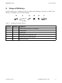
4 Scope of Delivery
Scope of Delivery
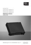
Check the delivery for completeness and any visible external damage. Contact your retailer if the
delivery is incomplete or you find any damage.
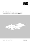
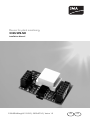
Figure 2:
Components included in delivery
Position
Quantity Designation
A
1
Communication interface 232USPB-NR
B
1
Insulating hose
C
1
Flat male tab
D
1
Cable gland with single seal insert
E
1
Counter nuts for the cable glands
F
1
Installation manual
Installation Manual
232USPB-NR-eng-IUS113210
13
5 Electrical Connection
5
SMA America, LLC
Electrical Connection
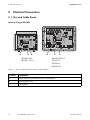
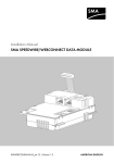
5.1 Slot and Cable Route
Inverter of type SB/WB
SB/WB 700-U
SB/WB 3000-US
SB/WB 1100-U
SB 3300-U
SB 3800-U
SB 4000-US
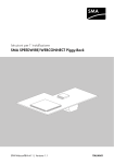
Figure 3:
Slot and cable route for inverters of type SB/WB
Position
Designation
A
Cable route from the interface slot to cable gland
B
Mounting tab for PE
C
Cable gland
14
232USPB-NR-eng-IUS113210
Installation Manual
SMA America, LLC
5 Electrical Connection
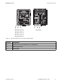
SB/WB 5000-US
SB 6000-U
SB/WB 6000-US
SB/WB 7000-US
SB/WB 8000-US
Figure 4:
Slot and cable route for inverters of type SB/WB
Position
Designation
A
Cable route from the interface slot to cable gland
B
Mounting tab for PE
C
Cable gland
Installation Manual
232USPB-NR-eng-IUS113210
15
5 Electrical Connection
SMA America, LLC
Inverter of type SWR
SWR 1800-U
SWR 2100-U
SWR 2500-U
Figure 5:
Slot and cable route for inverters of type SWR
Position
Designation
A
Cable route from the interface slot to cable gland
B
Cable gland
C
Mounting tab for PE
16
232USPB-NR-eng-IUS113210
Installation Manual
SMA America, LLC
5 Electrical Connection
5.2 Installing the Communication Interface
Risk of lethal electric shock
High voltages are present in the inverter.
• Before opening the inverter, disconnect AC and DC voltage.
Figure 6: Interface slot (example)
Position
Designation
A
Jumper slot
B
Screw terminal for connecting the communication cabling
C
Interface slot
D
Resistors*
* Only for inverters of type SWR
1. Open inverter (see inverter installation manual).
2. In case of an inverter of type SWR, remove the
resistors marked with a black ring. Use diagonal
cutting pliers.
Installation Manual
232USPB-NR-eng-IUS113210
17
5 Electrical Connection
SMA America, LLC
3. Plug in the communication interface flush-left on the
communication interface slot. Leave the two pins on
the right side of the short row of pins free.
5.3 Preparing the Enclosure Opening on the Inverter
1. Push the filler-plug out of the enclosure opening of
the inverter.
2. Insert the cable gland with single seal insert into the
enclosure opening and fasten it with a counter nut.
3. Loosen the nut of cable gland so that the cables can be inserted.
18
232USPB-NR-eng-IUS113210
Installation Manual
SMA America, LLC
5 Electrical Connection
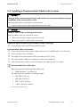
5.4 Installing a Communication Cable in the Inverter
Damage of the communication interface and interference of communication by improper
installation of the communication cable
Incorrectly laid cables can disturb the communication.
• Lay the communication cable separately from the AC cable.
Metal or cable scraps can damage the inverter
Metal or cable scraps can cause short circuits.
• Do not leave metal or cable scraps in the inverter.
• Remove any metal or cable scraps, if necessary.
Additional required material (not included in scope of delivery)
☐ Communication cable with DE9 plug (D-Sub 9-pole)
Communication cable requirements
☐ Cross section of the communication cable is at least 2 x 2 x AWG 24 (2 x 2 x 0.25 mm²).
☐ Communication cable is shielded.
☐ The length of the communication cable is at maximum 32 ft. (10 m).
☐ The communication cable has twisted pair conductors (twisted pair).
☐ If the communication cable is to be laid outdoors, the cable must be UV resistant.
Recommendation for cable types:
SMA recommends the following SMA cable types:
• COMCAB-INxxx* for indoor use
The cable types are available in following lengths:
• 100: 328 ft. (100 m)
• 200: 656 ft. (200 m)
• 500: 1 640 ft. (500 m)
• 1 000: 3 280 ft. (1 000 m)
* xxx stands for the cable length
Installation Manual
232USPB-NR-eng-IUS113210
19
5 Electrical Connection
SMA America, LLC
1. Guide the communication cable through the cable gland of the inverter.
2. Strip the communication cable to the length of the cable route.
3. Shorten unused insulated conductors until flush with the cable sleeve.
4. Shorten the shield of the cable to the length of the cable route for PE connection.
5. Twist the wires of the cable shield and combine it with a flat male tab.
6. Put the flat male tab on the mounting tab for PE
(see section 5.1 "Slot and Cable Route", page 14).
7. Strip 1⁄4 in. (6 mm) off the conductor insulation.
8. Tighten the nut of the cable gland to fix the
communication cable.
9.
Risk of lethal electric shock due to faulty installation
Communication cables incorrectly insulated and installed may cause high voltages.
• Pull the insulating hose over the
communication cable to ensure that the cable
is completely insulated. Do not insulate the
shield of the cable.
• Shorten the insulating hose to the length of the
cable route.
10. Lay the cable with insulating hose to the screw terminals. Observe the cable route
(see section 5.1).
20
232USPB-NR-eng-IUS113210
Installation Manual
SMA America, LLC
5 Electrical Connection
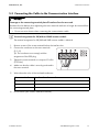
5.5 Connecting the Cable to the Communication Interface
Damage to the connecting terminal plate if bootlace ferrules are used
Bootlace ferrules deform when tightening the screw terminals and can no longer be removed from
the connecting terminal plate.
• Do not use wire sleeves when connecting the communication cable.
Terminal assignment for SB/WB and SWR inverter models
The terminal assignment for SB/WB and SWR inverter models is identical.
1. Remove screws of the screw terminals below the interface slot.
2. Connect the conductor to the screw terminals
(2, 3, 5).
Tip: The conductors must comply with the
assignment of the DE9 plug.
3. Tighten the screw terminals to a torque of 2 in-lbs
(0.23 Nm).
4. Make sure that the cable is securely positioned in
the screw terminal.
5. Write down the color of the insulated conductors:
Screw terminal
Insulated conductor color
2
3
5
6. Close inverter (see inverter installation manual).
Installation Manual
232USPB-NR-eng-IUS113210
21
6 Decommissioning
6
SMA America, LLC
Decommissioning
6.1 Disassembly
Risk of lethal electric shock
High voltages are present in the inverter during operation.
• Disconnect the inverter on the AC and DC side.
• Ensure that no voltage is present.
• Open the inverter as described in the installation manual of the inverter.
1. Remove the communication interface.
2. Remove the screw of the screw terminal and disconnect the insulated conductors.
3. Remove jumper where applicable.
4. Remove cable tie where applicable.
5. Remove the cable shield from the PE connector.
6. Remove the insulating hose.
7. Loosen the nut of the cable gland.
8. Pull the cable out of the device.
9. Remove the cable gland from the enclosure.
10. Plug the enclosure opening at the bottom of the inverter with a filler-plug.
11. Close inverter (see inverter installation manual).
6.2 Disposal
Dispose of the communication interface in accordance with the disposal regulations for electronic
waste which apply at the installation site at that time. Alternatively, send it back to SMA with shipping
paid by sender, and the information "ZUR ENTSORGUNG" ("FOR DISPOSAL").
22
232USPB-NR-eng-IUS113210
Installation Manual
SMA America, LLC
7
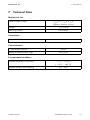
7 Technical Data
Technical Data
Mechanical size
Width x Height x Depth
17⁄64 in. x 121⁄32 in. x 5⁄8 in.
(28 mm x 42 mm x 16 mm)
Weight
1
Mounting location
in the inverter
⁄2 oz. (14 g)
Connections
Communication bus
in the inverter
Communication
Communication interface
Maximum communication range
RS232
32 ft. (10 m)
Environmental conditions
Ambient temperature in operation
− 13°F … +185°F
( − 25°C … +85°C)
Relative humidity, non-condensing
Installation Manual
5% … 95%
232USPB-NR-eng-IUS113210
23
8 FCC Compliance Information
8
SMA America, LLC
FCC Compliance Information
This device complies with Part 15 of the FCC Rules. Operation is subject to the following conditions:
1. This device may not cause harmful interference, and
2. This device must accept any interference received, including interference that may cause
undesired operation.
NOTE: This equipment has been tested and found to comply with the limits for a Class A & B digital
device, pursuant to Part 15 of the FCC Rules. These limits are designed to provide reasonable
protection against harmful interference in a residential installation. This equipment generates, uses,
and can radiate radio frequency energy and if not installed and used in accordance with the
instructions, may cause harmful interference to radio communications. However, there is no guarantee
that interference will not occur in a particular installation. If this equipment does cause harmful
interference to radio or television reception, which can be determined by turning the equipment off
and on, the user is encouraged to try to correct the interference by one or more of the following
measures:
• Reorient or relocate the receiving antenna.
• Increase the separation between the equipment and the receiver.
• Connect the equipment into an outlet on a circuit different from that to which the receiver is
connected.
• Consult the dealer or an experienced radio/TV technician for help.
• The user is cautioned that changes or modifications not expressly approved by SMA America,
Inc. could void the user’s authority to operate this equipment.
24
232USPB-NR-eng-IUS113210
Installation Manual
SMA America, LLC
9
9 Contact
Contact
If you have technical problems concerning our products, contact the SMA Service Line. We require
the following information in order to provide you with the necessary assistance:
• Type and serial number of inverter
• Type and number of modules connected
• Communication method
• Inverter failure or warning number
• Display message of the inverter
SMA Solar Technology America, LLC
6020 West Oaks Blvd, Ste 300
Rocklin, CA 95765
Tel. +1 916 625 0870
Tel. +1 877-MY SMA TECH
Tel. +1 877 697 6283 (Toll free, available for USA, Canada and Puerto Rico)
Fax +1 916 625 0871
[email protected]
www.SMA-America.com
SMA Solar Technology Canada Inc.
2425 Matheson Blvd E, 8th Floor
Mississauga, ON L4W 5K5, Canada
Tel. +1 877 506 1756 (Toll free, available for Canada)
[email protected]
www.SMA-Canada.ca
Installation Manual
232USPB-NR-eng-IUS113210
25
4."4PMBS5FDIOPMPHZ
XXX4."4PMBSDPN
4.""NFSJDB--$
XXX4.""NFSJDBDPN