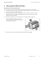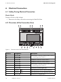
1
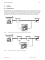
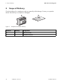
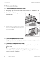
Accessories for power generation plants in Italy SMA GRID GATE Installation Manual GridGate-11-IA-en-12 | Version 1.2 EN SMA Solar Technology AG Table of Contents Table of Contents 1 Information on this Document. . . . . . . . . . . . . . . . . . . . . . . 5 2 2.1 2.2 2.3 Safety . . . . . . . . . . . . . . . . . . . . . . . . . . . . . . . . . . . . . . . . . . Intended Use. . . . . . . . . . . . . . . . . . . . . . . . . . . . . . . . . . . . . . . . Qualification of Skilled Persons . . . . . . . . . . . . . . . . . . . . . . . . . Safety Precautions. . . . . . . . . . . . . . . . . . . . . . . . . . . . . . . . . . . . 3 Scope of Delivery . . . . . . . . . . . . . . . . . . . . . . . . . . . . . . . . 10 4 4.1 4.2 4.3 4.4 4.5 Product Description . . . . . . . . . . . . . . . . . . . . . . . . . . . . . . 11 SMA Grid Gate . . . . . . . . . . . . . . . . . . . . . . . . . . . . . . . . . . . . 11 Type Label . . . . . . . . . . . . . . . . . . . . . . . . . . . . . . . . . . . . . . . . 12 Digital Inputs . . . . . . . . . . . . . . . . . . . . . . . . . . . . . . . . . . . . . . . 13 Adjustable Parameters . . . . . . . . . . . . . . . . . . . . . . . . . . . . . . . 13 Default Settings for CEI 0-21 . . . . . . . . . . . . . . . . . . . . . . . . . . 15 5 Mounting the SMA Grid Gate . . . . . . . . . . . . . . . . . . . . . . 17 6 6.1 6.2 6.3 Electrical Connection . . . . . . . . . . . . . . . . . . . . . . . . . . . . . 18 Safety During Electrical Connection . . . . . . . . . . . . . . . . . . . . . 18 Overview of the Connection Area . . . . . . . . . . . . . . . . . . . . . . 18 Connecting the SMA Grid Gate . . . . . . . . . . . . . . . . . . . . . . . . 19 7 Commissioning . . . . . . . . . . . . . . . . . . . . . . . . . . . . . . . . . . 22 8 8.1 8.2 8.3 8.4 8.5 8.6 Operation . . . . . . . . . . . . . . . . . . . . . . . . . . . . . . . . . . . . . . 23 Menu Structure . . . . . . . . . . . . . . . . . . . . . . . . . . . . . . . . . . . . . 23 Symbols in the Graphic Display . . . . . . . . . . . . . . . . . . . . . . . . 25 Overview . . . . . . . . . . . . . . . . . . . . . . . . . . . . . . . . . . . . . . . . . 26 Activating the Graphic Display . . . . . . . . . . . . . . . . . . . . . . . . . 26 Restoring Default Settings . . . . . . . . . . . . . . . . . . . . . . . . . . . . . 26 Deleting all Error Messages . . . . . . . . . . . . . . . . . . . . . . . . . . . 27 Installation Manual GridGate-11-IA-en-12 7 7 9 9 3 Table of Contents SMA Solar Technology AG 8.7 8.8 Trigger Test for Section Switches . . . . . . . . . . . . . . . . . . . . . . . 27 Manually Resetting Blockade of the SMA Grid Gate . . . . . . . 27 9 9.1 Troubleshooting . . . . . . . . . . . . . . . . . . . . . . . . . . . . . . . . . 28 LED Signals . . . . . . . . . . . . . . . . . . . . . . . . . . . . . . . . . . . . . . . . 28 9.2 9.3 9.4 Messages in the Status Bar. . . . . . . . . . . . . . . . . . . . . . . . . . . . 29 Error Messages. . . . . . . . . . . . . . . . . . . . . . . . . . . . . . . . . . . . . 33 Stored Error Messages . . . . . . . . . . . . . . . . . . . . . . . . . . . . . . . 35 10 Disconnecting the SMA Grid Gate from Voltage Sources . . . . . . . . . . . . . . . . . . . . . . . . . . . . . . . . . 37 11 11.1 11.2 11.3 Decommissioning . . . . . . . . . . . . . . . . . . . . . . . . . . . . . . . . 38 Disassembling the SMA Grid Gate . . . . . . . . . . . . . . . . . . . . . 38 Packaging the SMA Grid Gate . . . . . . . . . . . . . . . . . . . . . . . . 38 Disposing of the SMA Grid Gate . . . . . . . . . . . . . . . . . . . . . . . 38 12 Technical Data . . . . . . . . . . . . . . . . . . . . . . . . . . . . . . . . . . 39 13 Contact . . . . . . . . . . . . . . . . . . . . . . . . . . . . . . . . . . . . . . . . 41 4 GridGate-11-IA-en-12 Installation Manual SMA Solar Technology AG 1 1 Information on this Document Information on this Document Validity This document is valid for "GRIDGATE-11" device types. Target Group This document is for skilled persons. Only skilled persons are allowed to perform the tasks set forth in this document (see Section 2.2 "Qualification of Skilled Persons", page 9). Symbols Symbol Explanation Indicates a hazardous situation which, if not avoided, will result in death or serious injury Indicates a hazardous situation which, if not avoided, could result in death or serious injury Indicates a hazardous situation which, if not avoided, could result in minor or moderate injury Indicates a situation which, if not avoided, could result in property damage Information that is important for a specific topic or goal, but is not safetyrelevant ☐ Indicates an essential requirement for achieving a specific goal ☑ Desired result ✖ A problem that might occur Installation Manual GridGate-11-IA-en-12 5 1 Information on this Document SMA Solar Technology AG Typography Typography bold Usage Example • Select the DigIn2 parameter and set to ExtComm. • Display messages • Parameters • Connections • Slots • Elements to be selected • Elements to be entered > • Several elements that are to be selected • Select Settings > Date. Abbreviations 6 Abbreviation Description Explanation AC Alternating Current – MSL Mean Sea Level ‒ GridGate-11-IA-en-12 Installation Manual SMA Solar Technology AG 2 2 Safety Safety 2.1 Intended Use The SMA Grid Gate is an external grid and plant protection for use in Italy. It interrupts the connection between the power generation plant and the electricity grid in the event of disturbances in the voltage or frequency by controlling up to two section switches. The number of section switches depends on the plant power. In plants of between 6 kW and 20 kW, disconnection from the electricity grid is performed via one section switch. In plants of over 20 kW, two section switches are required. Figure 1: Principle of a plant of between 6 kW and 20 kW with SMA Grid Gate Figure 2: Principle of a plant of over 20 kW with SMA Grid Gate Installation Manual GridGate-11-IA-en-12 7 2 Safety SMA Solar Technology AG The SMA Grid Gate is suitable for indoor use only. The SMA Grid Gate does not replace the function of islanding detection. Islanding detection must be performed by the power generation plant. Furthermore, the SMA Grid Gate does not prevent unbalanced load. Protection against unbalanced load must also be ensured by the power generation plant. For safety reasons, it is not permitted to modify the product or install components that are not explicitly recommended or distributed by SMA Solar Technology AG for this product. Only use the SMA Grid Gate in accordance with the information provided in the enclosed documentation. Any other use may result in personal injury or property damage. The enclosed documentation is an integral part of this product. You must read and adhere to this documentation to enable proper and optimum use of the SMA Grid Gate. Keep the documentation in a convenient place for future reference. 8 GridGate-11-IA-en-12 Installation Manual SMA Solar Technology AG 2 Safety 2.2 Qualification of Skilled Persons The work described in this document must only be performed by skilled persons. Skilled persons must have the following qualifications: • Knowledge of how the device works and is operated • Training in how to deal with the dangers and risks involved in installing and operating electrical devices and plants • Training in the installation and commissioning of electrical devices and plants • Knowledge of the applicable standards and directives • Knowledge of and compliance with this document and all the safety precautions 2.3 Safety Precautions Electric Shock Risk of lethal electric shock if work on electrical devices is not performed properly • All work on the SMA Grid Gate must be performed by skilled persons only. • Disconnect electrical devices from any voltage sources before working on them. Electrostatic Discharge Touching electronic components may result in damage to and destruction of the SMA Grid Gate due to electrostatic discharge. • Earth yourself before touching any components. • Do not touch any components other than those described in this document. Changing Parameters Improper changing of parameters may result in grid failures, yield loss, damage to the power generation plant or the SMA Grid Gate and personal injury. The operating licence may also be revoked. • Always consult the network operator before changing parameters. Installation Manual GridGate-11-IA-en-12 9 3 Scope of Delivery 3 SMA Solar Technology AG Scope of Delivery Check the delivery for completeness and any externally visible damage. Contact your specialist dealer if the delivery is incomplete or damaged. Figure 3: Components included in delivery Position Quantity Designation A 1 SMA Grid Gate B 1 Installation manual 10 GridGate-11-IA-en-12 Installation Manual SMA Solar Technology AG 4 4 Product Description Product Description 4.1 SMA Grid Gate The SMA Grid Gate is an external grid and plant protection for use in Italy. It interrupts the connection between the power generation plant and the electricity grid in the event of disturbances in the voltage or frequency by controlling up to two section switches. The number of section switches depends on the plant power. In plants of between 6 kW and 20 kW, disconnection from the electricity grid is performed via one section switch. In plants of over 20 kW, two section switches are required. Figure 4: SMA Grid Gate Position Designation A SMA Grid Gate B Green LED C Red LED D Type label E Top button F Middle button G Bottom button H Graphic display The SMA Grid Gate monitors the three line conductors from the electricity grid for disturbances in the voltage and frequency. If the lower limit is not met or the upper limit is exceeded, the SMA Grid Gate disconnects the power generation plant from the electricity grid by opening two section switches. Installation Manual GridGate-11-IA-en-12 11 4 Product Description SMA Solar Technology AG 4.2 Type Label The type label is on the right-hand side of the SMA Grid Gate. Figure 5: Layout of the type label Position Designation Explanation A Type SMA Grid Gate device type B Serial Number SMA Grid Gate serial number C Device-specific characteristics ‒ You require the information on the type label to use the device safely and for customer support from the SMA Service Line. The type label must be permanently affixed to the SMA Grid Gate. Symbols on the Type Label Symbol 12 Designation Explanation CE marking The product conforms to the requirements of the applicable EC directives. Observe the documentation. Observe all documentation that is supplied with the product. Protection class II The product has protective insulation. The protective insulation prevents live electrical parts from being touched. WEEE designation Do not dispose of the product together with the household waste but in accordance with the locally applicable disposal regulations for electronic waste. GridGate-11-IA-en-12 Installation Manual SMA Solar Technology AG 4 Product Description 4.3 Digital Inputs The remote shutdown can be realised via the first digital input (D1), If the parameter DigIn1 is set to ExtOFF and no signal is present at D1, the remote shutdown will be active and the SMA Grid Gate switches the section switches off. The second digital input (D2) receives the communication signal. If the parameter DigIn2 is set to ExtComm and no signal from D2 is present, the communication does not work properly and the frequency is tested for the limits f<c and f>c. If the parameter DigIn1 or DigIn2 is set to Disabled, the function of the respective digital input will be deactivated. The voltage supply of the two digital inputs must be between 12 V and 24 V. 4.4 Adjustable Parameters Name Description Value/Range Resolution U<< Voltage drop protection 0 V ... 300 V 0.1 V U< Voltage drop protection 46 V ... 300 V 0.1 V U>> Voltage rise protection 46 V ... 300 V 0.1 V U> Voltage rise protection 46 V ... 300 V 0.1 V Ua> Voltage rise protection, adjustable average value in minutes 46 V ... 300 V 0.1 V t(U<<) Disconnection time for U<< 0.04 s … 300 s 0.02 s t(U<) Disconnection time for U< 0.04 s … 300 s 0.02 s t(U>>) Disconnection time for U>> 0.04 s … 300 s 0.02 s t(U>) Disconnection time for U> 0.04 s … 300 s 0.02 s t(Ua>) Disconnection time for Ua> 0.2 s … 10 s 0.02 s T(Ua>) Duration for average value Ua> 1 min … 15 min 1 min f<< Frequency drop protection 44 Hz … 65 Hz 0.01 Hz f< Frequency drop protection 44 Hz … 65 Hz 0.01 Hz f<c Frequency drop protection, if no communication 44 Hz … 65 Hz 0.01 Hz f>> Frequency rise protection 44 Hz … 65 Hz 0.01 Hz f> Frequency rise protection 44 Hz … 65 Hz 0.01 Hz f>c Frequency rise protection, if no communication 44 Hz … 65 Hz 0.01 Hz t(f<<) Disconnection time for f<< 0.04 s … 300 s 0.02 s Installation Manual GridGate-11-IA-en-12 13 4 Product Description SMA Solar Technology AG Name Description Value/Range Resolution t(f<) Disconnection time for f< 0.04 s … 300 s 0.02 s t(f<c) Disconnection time for f<c 0.04 s … 300 s 0.02 s t(f>>) Disconnection time for f>> 0.04 s … 300 s 0.02 s t(f>) Disconnection time for f> 0.04 s … 300 s 0.02 s t(f>c) Disconnection time for f>c 0.04 s … 300 s 0.02 s Recon Min U Reconnection threshold undervoltage 46 V ... 300 V 0.1 V Recon Max U Reconnection threshold overvoltage 46 V ... 300 V 0.1 V Recon Min f Reconnection threshold underfrequency 44 Hz … 65 Hz 0.01 Hz Recon Max f Reconnection threshold overfrequency 44 Hz … 65 Hz 0.01 Hz Start time Connection time after start 2 s … 1 600 s 1s Connection time Reconnection time after normal grid error 0 s … 1 600 s 1s SB Maximum duration of a short interruption (short break) 0 s … 400 s* 1s Time after SB Reconnection time after SB 2 s … 1600 s 1s DigIn1 Setting of the first digital input Disabled, ‒ ExtOFF DigIn2 Setting of the second digital input t(ExtOFF) Disconnection time for remote shutdown Country data set Country data set used Number of relays Number of section switches used Disabled, ‒ ExtComm 0.02 s …10 s 0.02 ms CEI 0-21 ‒ 1, 2 ‒ * If SB = 0 s, the short interruption is deactivated. 14 GridGate-11-IA-en-12 Installation Manual SMA Solar Technology AG 4 Product Description 4.5 Default Settings for CEI 0-21 The SMA Grid Gate has the following default values for CEI 0-21 in order to meet the requirements of the CEI 0-21. Observe Limiting Values Pay attention to ensuring that no disconnection thresholds are exceeded or undercut. Additionally, no remote shutdown command must be present via the first digital input D1. Disconnection Conditions Function Limiting value Disconnection time Voltage drop protection U<< 92.0 V 200 ms Voltage drop protection U< 195.5 V 400 ms Voltage drop protection U>> 300.0 V 300 s Voltage increase protection U> 264.5 V 200 ms Voltage increase protection Ua>, (Default setting of average value length = 10 min) 253.0 V 2s -- 20 ms 44.0 Hz 300 s Disconnection time for remote shutdown* Frequency drop protection f<< Frequency drop protection f< 47.5 Hz 100 ms Frequency drop protection, if no communication f<c** 49.5 Hz 100 ms Frequency increase protection f>> 65.0 Hz 300 s Frequency increase protection f> 51.5 Hz 100 ms Frequency increase protection, if no communication f>c** 50.5 Hz 100 ms * Can be activated using the first digital input DigIn1. ** Can be activated using the second digital input DigIn2. Installation Manual GridGate-11-IA-en-12 15 4 Product Description SMA Solar Technology AG Connection Conditions Function Limiting value Connection time* ‒ 30 s Upper voltage limit after start 253.0 V 30 s Lower voltage limit after start 195.5 V 30 s Upper frequency limit after start 50.1 Hz 30 s Lower frequency limit after start 49.9 Hz 30 s ‒ 0s Connection time after start Reconnection time after fault Upper voltage limit after grid error 300.0 V 100 ms Lower voltage limit after grid error 46.0 V 100 ms Upper frequency limit after grid error 65.0 Hz 100 ms Lower frequency limit after grid error 44.0 Hz 100 ms Maximum duration of a short interruption ‒ 0 s** Reconnection time after short interruption ‒ 5s * The values must be within the limits during the connection period. ** 0 s = deactivated 16 GridGate-11-IA-en-12 Installation Manual SMA Solar Technology AG 5 5 Mounting the SMA Grid Gate Mounting the SMA Grid Gate Requirements for the mounting location: ☐ The top-hat rail for mounting must be mounted in the switch cabinet or meter cabinet. ☐ The mounting location must be suitable for the weight and dimensions of the SMA Grid Gate (see Section 12 "Technical Data", page 39). ☐ The mounting location must be easy and safe to access at all times, without the need for additional aids (e.g. scaffolding or lifting platforms). If this is not the case, future service assignments may be restricted. ☐ The climatic conditions must be met (see Section 12 "Technical Data", page 39). 1. Position the SMA Grid Gate with the upper enclosure bracket on the top-hat rail and push it back against the top-hat rail. 2. Push the lower enclosure bracket back until the SMA Grid Gate engages. Installation Manual GridGate-11-IA-en-12 17 6 Electrical Connection 6 SMA Solar Technology AG Electrical Connection 6.1 Safety During Electrical Connection Electric Shock Danger to life due to high voltages • Observe the five safety rules before connecting the SMA Grid Gate. 6.2 Overview of the Connection Area Figure 6: Connection area of the SMA Grid Gate Position Designation Description A Terminal R1 B Terminal R2 Potential-free switching contact (make contact) for controlling section switch 1 C Terminal K1 Feedback contact for section switch 1 D Terminal K2 Feedback contact for section switch 2 E Terminal R3 F Terminal R4 Potential-free switching contact (make contact) for controlling section switch 2 G Terminal D2 Terminal for second digital input H Terminal Earth terminal for D2 for remote shutdown I Terminal Earth terminal for D1 for frequency restriction K Terminal D1 Terminal for first digital input 18 GridGate-11-IA-en-12 Installation Manual SMA Solar Technology AG 6 Electrical Connection Position Designation Description L Terminal L3 Measuring contact for line conductor L3 M Terminal L2 Measuring contact for line conductor L2 N Terminal L1 Measuring contact for line conductor L1 and voltage supply O Terminal N Terminal for neutral conductor N 6.3 Connecting the SMA Grid Gate Additionally required material (not included in scope of delivery): ☐ For a plant power of between 6 kW and 20 kW, there must be one section switch for grid disconnection. ☐ For a plant power of over 20 kW, there must be two section switches for grid disconnection. ☐ Rigid or flexible cable ☐ For flexible cables: bootlace ferrules with insulation ☐ Fuses for the SMA Grid Gate: maximum 16 A Requirements for the section switches: ☐ The section switches must be designed according to the plant power. ☐ The section switches must have a switch-on delay of no more than 20 s. ☐ The section switches must have a switch-off time of no more than 50 ms. ☐ Category of section switches for power generation plants with provision of reactive power: AC3. ☐ Category of section switches for power generation plants with no provision of reactive power: AC1. Cable requirements: ☐ External diameter: 0.5 mm ... 1.8 mm ☐ Conductor cross-section: 0.2 mm² ... 2.5 mm² ☐ Cable length for connecting the digital inputs must not exceed 30 m. Installation Manual GridGate-11-IA-en-12 19 6 Electrical Connection SMA Solar Technology AG Connection diagram without feedback contact Figure 7: 20 Connection diagrams without feedback contact: 1 section switch for installations from 6 kW to 20 kW and 2 section switches for installations over 20 kW GridGate-11-IA-en-12 Installation Manual SMA Solar Technology AG 6 Electrical Connection Connection diagram with feedback contact Figure 8: Connection diagrams with feedback contact: 1 section switch for installations from 6 kW to 20 kW and 2 section switches for installations over 20 kW 1. Strip 8 mm from the cable insulation. 2. For flexible cables, push bootlace ferrules onto the cable ends. 3. Release the screw terminal using a screwdriver. 4. Lay the cables in the cable route according to the connection diagram and use a screwdriver to tighten the screw terminal (torque: 0.5 Nm ... 0.6 Nm). 5. When using 1 section switch, connect the section switch exclusively to terminals R1, R2 and K1. No other connection combination is possible here. 6. Make sure that the cables are positioned securely in the terminal blocks Installation Manual GridGate-11-IA-en-12 21 7 Commissioning 7 SMA Solar Technology AG Commissioning 1. Switch on the fuse of the SMA Grid Gate. 2. Switch on the miniature circuit-breaker of the electricity grid. 3. Commission the power generation plant (see installation manual of power generation plant). 4. Use the middle button to confirm Italiano as the language. ✖ Does the graphic display indicate an error? • Eliminate the error (see Section 9.3 "Error Messages", page 33). 5. Use the middle button to confirm the country data set CEI 0-21. ✖ Does the graphic display indicate an error? Eliminate the error (see Section 9.3 "Error Messages", page 33). 6. Select the number of section switches: • For a plant power of over 20 kW, use the middle button to confirm 2 (>20KW). • For a plant power of between 6 kW and 20 kW, use the arrow button to select 1 (<=20kW) and use the middle button to confirm. ☑ The graphic display shows the Overview after the self-test and grid check. ✖ Does the graphic display indicate an error? It is likely that the connection of the SMA Grid Gate is incorrect. • Eliminate the error (see Section 9.3 "Error Messages", page 33). ☑ If the voltage and frequency are within the permissible range for 30 seconds and no buttons are pressed, the SMA Grid Gate closes the section switches. The power generation plant can only feed into the electricity grid once this has occurred. 22 GridGate-11-IA-en-12 Installation Manual SMA Solar Technology AG 8 8 Operation Operation 8.1 Menu Structure Main menu Language Indicates the languages available for the display messages. German As language, select German. Italiano As language, select Italian. English As language, select English. Parameter display Enables you to read out the current parameter settings. Voltage N-L Indicates voltage thresholds with corresponding disconnection times for the individual line conductors to the neutral conductor. Voltage L-L Indicates voltage thresholds with corresponding disconnection times between the line conductors. Frequency Indicates frequency thresholds with corresponding disconnection times for frequency variation. Connection limits Gives an overview of all limits for voltage and frequency. Connection times Gives an overview of all connection times. Further parameters Shows the current settings of the following parameters: • Digital inputs DigIn1 and DigIn2 • t(ExtOFF): Disconnection time for remote shutdown • Number of relays Error messages Installation Manual Enables you to view the last 12 error messages that led to a disconnection. GridGate-11-IA-en-12 23 8 Operation SMA Solar Technology AG Main menu Configuration Main menu 24 Enables you to set parameter values and delete error messages. You must enter the SMA Grid Guard code before parameter configuration. Set disconnect para Enables you to set all available disconnection parameters. Set connection para Enables you to set all available connection parameters. Number of relays Enables you to select the number of section switches. Configure DigIn Enables you to activate and deactivate the function of digital inputs DigIn1 and DigIn2. Country data set Enables you to select the country data set, which sets all parameters according to the country standard. Changes that have been made manually are lost. Delete errors Enables you to delete all entries in the error list. → Main menu Takes you back to the main menu. Info Displays the serial number and firmware version of the SMA Grid Gate. → Overview Gives an overview of the voltages, power frequency and status messages. GridGate-11-IA-en-12 Installation Manual SMA Solar Technology AG 8 Operation 8.2 Symbols in the Graphic Display Operation of the SMA Grid Gate is via the 3 buttons next to the graphic display. The meaning of the buttons is shown next to the respective button in the graphic display. Symbol Description Main menu Confirm selection Scroll upwards or downwards line by line Scroll upwards or downwards page by page Back Error messages* Trigger test for the section switches Communication active If the parameter DigIn2 is set to ExtComm and voltage is present at D2, this symbol appears in the first line of the overview.** Communication not active If the parameter DigIn2 is set to ExtComm and no voltage is present at D2, this symbol appears in the first line of the overview.** Adj Abbreviation for "Adjusted". The country data set used appears in the first line of the overview. If at least 1 parameter has been changed within the country data set used, the suffix Adj appears alongside the country data set. * The symbol blinks if there are new error messages. ** If the parameter DigIn2 is deactivated, no symbol for communication appears in the first line. Installation Manual GridGate-11-IA-en-12 25 8 Operation SMA Solar Technology AG 8.3 Overview The Overview display shows the status of the SMA Grid Gate. Figure 9: Screen of the graphic display during operation Position Description A Country data set, Adj, symbol for communication* B Voltage between L1-L2, L2-L3 and L3-L1 C Status bar** D Power frequency E Voltage between N-L1, N-L2 and N-L3 * If you have altered parameters within the country data set, the suffix Adj will be shown in the display. The symbol for communication will be displayed if the parameter DigIn2 is set to ExtComm. ** In the status bar you will be shown the status messages (status messages see Section 9.2). 8.4 Activating the Graphic Display The graphic display deactivates itself automatically after 15 minutes, except during the start phase. • Press any button to activate the graphic display. ☑ The SMA Grid Gate shows the Overview. 8.5 Restoring Default Settings You can restore the default settings by reloading the country data set. 1. Select Main menu > Configuration. 2. Enter the SMA Grid Guard code. 3. Select Country data set. 4. Confirm CEI 0-21 with middle button. 26 GridGate-11-IA-en-12 Installation Manual SMA Solar Technology AG 8 Operation 8.6 Deleting all Error Messages 1. Select Main menu > Configuration. 2. Enter the SMA Grid Guard code. When so doing, select the desired figures with the upper and lower button and confirm with the middle button. 3. Select Delete errors. 4. Hold middle button pressed for 3 seconds. 8.7 Trigger Test for Section Switches 1. Press upper button in the main menu. 2. Hold middle button pressed for 3 seconds. ☑ An error will be triggered and both section switches open. After 30 s the SMA Grid Gate again closes the section switches and returns to normal operation. 8.8 Manually Resetting Blockade of the SMA Grid Gate For Installations over 20 kW If a section switch does not open correctly following triggering of an error, the SMA Grid Gate will automatically be blocked. The blockade can only be reset manually. Requirements: ☐ At least 1 section switch fails to open following triggering of an error. ☐ The LEDs flash alternately and the following error message appears in the Overview in the graphic display: Blocked connection due to relay error. To override block press top button for 3s. ☐ If the error is in the first section switch, ERR R:K1>> appears in the bottom line. ☐ If the error is in the second section switch, ERR R:K2>> appears in the bottom line. Proceed as follows to reset the blockade: 1. Select Main menu > Overview. 2. If the error message Blocked connection due to relay error. To override block press top button for 3s. ERR R:K1>> or ERR R:K2>> appears, hold upper button pressed for 3 s. ☑ Please wait now appears in the bottom line. The blockade will be reset. For Installations from 6 kW to 20 kW Blockade of the Section Switch Deactivated During operation with 1 section switch, the blockade of the section switch is deactivated. Installation Manual GridGate-11-IA-en-12 27 9 Troubleshooting 9 SMA Solar Technology AG Troubleshooting 9.1 LED Signals The LEDs indicate the operating state of the SMA Grid Gate. The green LED indicates that the SMA Grid Gate is operating. The red LED indicates errors. Red LED Green LED Explanation and corrective measures Glowing Off Grid error (voltage or frequency) Flashes once Off Hardware error Corrective measures: • Contact SMA Service Line. Flashes twice Off Section switch error Corrective measures: • Make sure that the SMA Grid Gate connection is correct. • Make sure that the section switches are functioning correctly. Replace section switches if necessary. Off Flashing Start phase or connection Off Glowing Normal operation Flashing Flashing Parameters are being set. Section switches are open. Alternate flashing During operation with 2 section switches, 1 section switch has not opened correctly following an error. The SMA Grid Gate is blocked. Corrective measures: • Check function of the section switches and eliminate the error displayed (see Section 9 "Troubleshooting", page 28). • Reset blockade manually (see Section 8.8 "Manually Resetting Blockade of the SMA Grid Gate", page 27). 28 GridGate-11-IA-en-12 Installation Manual SMA Solar Technology AG 9 Troubleshooting 9.2 Messages in the Status Bar The following status and error messages can be displayed in the status bar. The error messages can result from hardware errors, relay errors or grid errors. Message Explanation and corrective measures LOCKED Parameters are being set. Section switches are open. The SMA Grid Gate cannot connect. ExtOFF (XX) The parameter DigIn1 is set to ExtOFF and no voltage is present at D1. "XX" stands for the number of remote shutdowns up until the present time. R12 ON, wait for K1 Connection of power generation plant to electricity grid Waiting for feedback contact K1, until 75% of voltage of phase 1 is exceeded. R34 ON, wait for K2 Connection of power generation plant to electricity grid Waiting for feedback contact K2, until 75% of voltage of phase 1 is exceeded. This message only appears during operation with 2 section switches. ON Wxxxx Normal operation Waiting following grid error Before the power generation plant is connected to the electricity grid following a grid error, the SMA Grid Gate waits for the set connection time. "xxxx" stands for the remaining waiting time in seconds. Wxxxx START Start phase During the start phase the section switches are open. "xxxx" stands for the remaining waiting time in seconds. ERR: Par(73) At least 1 incorrect parameter has been found. Possible cause: Sudden switching off of the SMA Grid Gate when setting parameters. Corrective measures: • Restore default settings (see Section 8.5). ERR: Par(82) The country data sets of the two microcontrollers are not identical. Possible cause: Sudden switching off of the SMA Grid Gate when setting parameters. Corrective measures: • Restore default settings (see Section 8.5). ERR: H1: xxxxxxxx Hardware errors ERR: H2: xxxxxxxx Corrective measures: • Contact SMA Service Line. Installation Manual GridGate-11-IA-en-12 29 9 Troubleshooting SMA Solar Technology AG Message Explanation and corrective measures ERR R:K1>> Voltage on feedback contact K1 too high Corrective measures: • Make sure that the SMA Grid Gate connection is correct. • Make sure that the section switches are functioning correctly. Replace section switches if necessary. ERR R:K2>> Voltage on feedback contact K2 too high Corrective measures: • Make sure that the SMA Grid Gate connection is correct. • Make sure that the section switches are functioning correctly. Replace section switches if necessary. ERR R:K1? Connection procedure of section switch 1 has failed. Corrective measures: • Make sure that the SMA Grid Gate connection is correct. • Make sure that the section switches are functioning correctly. Replace section switches if necessary. ERR R:K2? Connection procedure of section switch 2 has failed. Corrective measures: • Make sure that the SMA Grid Gate connection is correct. • Make sure that the section switches are functioning correctly. Replace section switches if necessary. ERR R:K1?? Voltage on feedback contact K1 too low although section switch 1 is closed Corrective measures: • Make sure that the SMA Grid Gate connection is correct. • Make sure that the section switches are functioning correctly. Replace section switches if necessary. ERR R:K2?? Voltage on feedback contact K2 too low although section switch 2 is closed Corrective measures: • Make sure that the SMA Grid Gate connection is correct. • Make sure that the section switches are functioning correctly. Replace section switches if necessary. 30 GridGate-11-IA-en-12 Installation Manual SMA Solar Technology AG 9 Troubleshooting Message Explanation and corrective measures ERR R:K1<->K2 Feedback contact interchanged Corrective measures: • Make sure that the connection of the feedback contacts is correct. ERR R:RELTEST Trigger test for the section switches has been carried out. Corrective measures: • Wait until time set under Connection time has expired. ERR R: Finish LOCK LOCKED status ended ERR L1 U<< Undervoltage N-L1 ERR L2 U<< Undervoltage N-L2 ERR L3 U<< Undervoltage N-L3 ERR L12 U<< Undervoltage L1-L2 ERR L23 U<< Undervoltage L2-L3 ERR L31 U<< Undervoltage L3-L1 ERR L1 U< Undervoltage N-L1 ERR L2 U< Undervoltage N-L2 ERR L3 U< Undervoltage N-L3 ERR L1 U> Overvoltage N-L1 ERR L2 U> Overvoltage N-L2 ERR L3 U> Overvoltage N-L3 ERR L1 U>> Overvoltage N-L1 ERR L2 U>> Overvoltage N-L2 ERR L3 U>> Overvoltage N-L3 ERR L12 U< Undervoltage L1-L2 ERR L23 U< Undervoltage L2-L3 ERR L31 U< Undervoltage L3-L1 ERR L12 U> Overvoltage L1-L2 ERR L23 U> Overvoltage L2-L3 ERR L31 U> Overvoltage L3-L1 ERR L12 U>> Overvoltage L1-L2 ERR L23 U>> Overvoltage L2-L3 ERR L31 U>> Overvoltage L3-L1 ERR L1 Ua> Overvoltage N-L1 (10 minutes average value) Installation Manual GridGate-11-IA-en-12 31 9 Troubleshooting SMA Solar Technology AG Message Explanation and corrective measures ERR L2 Ua> Overvoltage N-L2 (10 minutes average value) ERR L3 Ua> Overvoltage N-L3 (10 minutes average value) ERR L12 Ua> Overvoltage L1-L2 (10 minutes average value)) ERR L23 Ua> Overvoltage L2-L3 (10 minutes average value) ERR L31 Ua> Overvoltage L3-L1 (10 minutes average value) ERR f<< Under-frequency ERR f< Under-frequency ERR f<c Under-frequency* ERR f>> Over-frequency ERR f> Over-frequency ERR f>c Over-frequency* * This error is only present if DigIn2 is set to ExtComm and no communication is active at D2. 32 GridGate-11-IA-en-12 Installation Manual SMA Solar Technology AG 9 Troubleshooting 9.3 Error Messages The following error messages can appear in the graphic display in the following situations: • In the start phase • When locking and unlocking the SMA Grid Gate • When setting and altering parameters • When setting the country data set Error message Explanation and corrective measures For locking the device The communication of the two microcontrollers is disturbed. Corrective measures: • Disconnect the SMA Grid Gate from voltage sources (see Section 10). • Wait 1 minute. • Re-commission the SMA Grid Gate (see Section 7). This selection not possible due to undervoltage The country data set cannot be loaded due to undervoltage. • Corrective measures: • Make sure that the SMA Grid Gate connection is correct. • Press bottom button. • Reload country data set or reselect the number of section switches. For parameters to load The communication of the two microcontrollers is disturbed. Corrective measures: • Reload country data set (see Section 8.5). Disallowed due to parameter error Parameter error Corrective measures: • Reload country data set (see Section 8.5). For setting the parameter Error when setting a parameter Corrective measures: • Re-set the parameter. For setting the new parameter checksum The communication of the two microcontrollers is disturbed or the parameter check sum cannot be written. Corrective measures: • Ensure that sufficient voltage is present. • Re-set the parameter. Installation Manual GridGate-11-IA-en-12 33 9 Troubleshooting SMA Solar Technology AG Error message Explanation and corrective measures At conclusion of initialization Error during the start phase For unlocking the device The communication of the two microcontrollers is disturbed. Corrective measures: • Re-set number of section switches. Corrective measures: • If the error message appears when selecting the number of section switches, proceed as follows: • Press bottom button. • Re-set number of section switches. • If the error message appears after entry of the SMA Grid Guard code and the status LOCKED appears in the status bar of the Overview, proceed as follows: • Disconnect the SMA Grid Gate from voltage sources (see Section 10). • Wait 1 minute. • Re-commission the SMA Grid Gate (see Section 7). 34 GridGate-11-IA-en-12 Installation Manual SMA Solar Technology AG 9 Troubleshooting 9.4 Stored Error Messages The SMA Grid Gate stores the last 12 error messages that have resulted in disconnection of the SMA Grid Gate. These can be read in the Error messages menu. Message Explanation and corrective measures 1 U<< Undervoltage N-L1 2 U<< Undervoltage N-L2 3 U<< Undervoltage N-L3 4 U<< Undervoltage L1-L2 5 U<< Undervoltage L2-L3 6 U<< Undervoltage L3-L1 7 U>> Overvoltage N-L1 8 U>> Overvoltage N-L2 9 U>> Overvoltage N-L3 10 U>> Overvoltage L1-L2 11 U>> Overvoltage L2-L3 12 U>> Overvoltage L3-L1 13 U< Undervoltage N-L1 14 U< Undervoltage N-L2 15 U< Undervoltage N-L3 16 U< Undervoltage L1-L2 17 U< Undervoltage L2-L3 18 U< Undervoltage L3-L1 19 U> Overvoltage N-L1 20 U> Overvoltage N-L2 21 U> Overvoltage N-L3 22 U> Overvoltage L1-L2 23 U> Overvoltage L2-L3 24 U> Overvoltage L3-L1 31 Ua> Overvoltage N-L1 (10 minutes average value) 32 Ua> Overvoltage N-L2 (10 minutes average value) 33 Ua> Overvoltage N-L3 (10 minutes average value) 34 Ua> Overvoltage L1-L2 (10 minutes average value) 35 Ua> Overvoltage L2-L3 (10 minutes average value) Installation Manual GridGate-11-IA-en-12 35 9 Troubleshooting SMA Solar Technology AG Message Explanation and corrective measures 36 Ua> Overvoltage L3-L1 (10 minutes average value) 52 f<< Under-frequency 53 f>> Over-frequency 54 f< Under-frequency 55 f< Over-frequency 56 f<c Under-frequency 57 f>c Over-frequency 61 K?? Voltage at feedback contact too low 64 RT Trigger test for the section switches has been carried out. 73 PAR At least 1 incorrect parameter has been found. Possible cause: Sudden switching off of the SMA Grid Gate when setting parameters. Corrective measures: • Restore default settings (see Section 8.5). 82 PAR The country data sets of the two microcontrollers are not identical. Possible cause: Sudden switching off of the SMA Grid Gate when setting parameters. Corrective measures: • Restore default settings (see Section 8.5). XX HRD Hardware error Corrective measures: • Contact SMA Service Line. 36 GridGate-11-IA-en-12 Installation Manual SMA Solar Technology AG 10 Disconnecting the SMA Grid Gate from Voltage Sources 10 Disconnecting the SMA Grid Gate from Voltage Sources 3. De-commission the power generation plant (see installation manual of power generation plant). 4. Disconnect the miniature circuit-breaker of the electricity grid and secure against reconnection. 5. Switch off fuses of the SMA Grid Gate. 6. Wait 1 minute before the SMA Grid Gate switches off completely. 7. Ensure that no voltage is present. Installation Manual GridGate-11-IA-en-12 37 11 Decommissioning SMA Solar Technology AG 11 Decommissioning 11.1 Disassembling the SMA Grid Gate 1. Disconnect the SMA Grid Gate from voltage sources (see Section 10). When doing so, take note of the five safety rules. 2. Release the screw terminal using a screwdriver and remove the cable. 3. Press the retaining clamp down using a screwdriver and remove the SMA Grid Gate from the top-hat rail by turning it gently. 11.2 Packaging the SMA Grid Gate • Package the SMA Grid Gate. To do so, use the original packaging or packaging that is suitable for the weight and size of the SMA Grid Gate. 11.3 Disposing of the SMA Grid Gate • Dispose of the SMA Grid Gate in accordance with the applicable disposal regulations for electronic waste. or • Return the SMA Grid Gate to SMA Solar Technology AG at your own expense (see section 13 "Contact", page 41). When doing so, label the packaging with the information "ZUR ENTSORGUNG" (for disposal). 38 GridGate-11-IA-en-12 Installation Manual SMA Solar Technology AG 12 Technical Data 12 Technical Data AC input AC line voltage AC voltage range Connection line conductors AC power frequency Operating range for AC power frequency Typical power consumption 230 V 46 V ... 300 V 3/N 50 Hz 44 Hz … 52 Hz 1W Digital inputs Voltage supply 12 V … 24 V Section Switch/Feedback Contact Maximum control voltage Maximum control current 250 V 6A Protective Devices AC short-circuit current capability Protection class according to IEC 62103) Overvoltage category as per IEC 60664-1 16 A II III Climatic Conditions for Operation Climatic class as per IEC 60721-3-3 Temperature range Humidity range* Air pressure range Degree of protection Altitude above MSL 3K5 − 20°C … +50°C 10% … 90% 70 kPa … 106 kPa IP20 0 m … 3,000 m * non-condensing Climatic Conditions for Storage/Transport Temperature range Relative humidity, non-condensing Altitude above MSL Installation Manual − 40°C … 70°C 5% … 95% 0 m … 10,500 m GridGate-11-IA-en-12 39 12 Technical Data SMA Solar Technology AG General Data Width x height x depth Weight Mounting location Measurement accuracy 100 mm x 75 mm x 55 mm 200 g Indoors, protected from dust and water 1% Features Connection Status display Display Country standards 40 GridGate-11-IA-en-12 Screw terminal 2 LEDs Graphic display CEI 0-21 Installation Manual 60$6RODU7HFKQRORJ\$*_6RQQHQDOOHH_1LHVWHWDO_*HUPDQ\ 3KRQH_)D[_,QWHUQHWZZZ60$GH_(PDLOLQIR#60$GH 5HJLVWHUFRXUW$PWVJHULFKW.DVVHO+5% &KDLUPDQRIWKH6XSHUYLVRU\%RDUG*QWKHU&UDPHU 0DQDJLQJ%RDUG-UJHQ'ROOH5RODQG*UHEH3LHUUH3DVFDO8UERQ0DUNR:HUQHU 13 Contact (&'HFODUDWLRQRI&RQIRUPLW\ If you have technical problems concerning our products, contact the SMA Service Line. We require ZLWKWKH*XLGHOLQHVRIWKH(XURSHDQ the following information in order to provide you with the necessary assistance: • SMA Grid Gate device type (OHFWURPDJQHWLF&RPSOLDQFH(& /RZ9ROWDJH(& • SMA Grid Gate serial number 7KHGHYLFHOLVWHGEHORZKDVEHHQGHYHORSHGGHVLJQHGDQGPDQXIDFWXUHGLQDFFRUGDQFHZLWKWKHDERYHPHQWLRQHG(&GLUHFWLYHV • LED signals and readouts from the graphic display of the SMA Grid Gate 7KHDSSOLHGKDUPRQL]HGVWDQGDUGVDUHVKRZQLQWKHIROORZLQJWDEOH 60$*ULG*DWH *5,'*$7( (OHFWURPDJQHWLFLQWHUIHUHQFH (1 ๓ (1 ๓ *ULGSHUWXUEDWLRQV (1$$ ๓ (1 ๓ (OHFWURPDJQHWLFFRPSDWLELOLW\ (1 ๓ (1 ๓ 'HYLFHVDIHW\ (1 ๓ ๓ 6WDQGDUGDSSOLFDEOH ๖ 6WDQGDUGQRWDSSOLFDEOH SMA Solar Technology AG Sonnenallee 1 34266 Niestetal, Germany www.SMA.de SMA Service Line +49 561 9522 1499 Communication: +49 561 9522 2499 ,QIRUPDWLRQ Fax: +49 561 9522 4699 LI E‑Mail: [email protected] 1LHVWHWDO 60$6RODU7HFKQRORJ\$* :LWKRXWDQH[SOLFLWZULWWHQFRQÀUPDWLRQE\60$WKLVGHFODUDWLRQRIFRQIRUPLW\LVQRORQJHUYDOLG WKHSURGXFWLVPRGLÀHGVXSSOHPHQWHGRUFKDQJHGLQDQ\RWKHUZD\ FRPSRQHQWVZKLFKDUHQRWSDUWRIWKH60$DFFHVVRULHVNLWDUHLQWHJUDWHGLQWKHSURGXFWDV ZHOODVLIWKHSURGXFWLVXVHGRULQVWDOOHGLPSURSHUO\ SSD)UDQN*UHL]HU 9LFH3UHVLGHQW0373' **=(&(HQ Inverters 'HFODUDWLRQRI&RQIRUPLW\ ZLWK*HUPDQ(XURSHDQDQG,QWHUQDWLRQDO1RQ(XURSHDQVWDQGDUGVXVHGIRU 60$*5,'*$7( (XURSHDQ6WDQGDUG (1 ,QWHUQDWLRQDO6WDQGDUG ,(&,(&&,635 ',1(1 EDVHGRQ (1 EDVHGRQ ,(& ',1(1 EDVHGRQ (1 EDVHGRQ ,(& ',1(1 EDVHGRQ (1 EDVHGRQ ,(& ',1(1 EDVHGRQ (1 EDVHGRQ ,(& ',1(1 EDVHGRQ (1 $$ EDVHGRQ ,(& $$ ',1(1 EDVHGRQ (1 EDVHGRQ ,(& ',1(1 EDVHGRQ (1 EDVHGRQ ,(& ',1(1 EDVHGRQ (1 EDVHGRQ ,(& ',1(1 EDVHGRQ (1 EDVHGRQ ,(& **=('HFN&(HQ *HUPDQ6WDQGDUG ',1(1 SMA Solar Technology AG Legal Restrictions The information contained in this document is the property of SMA Solar Technology AG. Publishing its content, either partially or in full, requires the written permission of SMA Solar Technology AG. Any internal company copying of the document for the purposes of evaluating the product or its correct implementation is allowed and does not require permission. SMA Factory Warranty The current warranty conditions come enclosed with your device. These are also available online at www.SMA-Solar.com and can be downloaded and are available on paper from the usual sales channels if required. Trademarks All trademarks are recognized even if these are not marked separately. Missing designations do not mean that a product or brand is not a registered trademark. The Bluetooth® word mark and logos are registered trademarks owned by Bluetooth SIG, Inc. and any use of such marks by SMA Solar Technology AG is under licence. QR Code® is a registered trademark of DENSO WAVE INCORPORATED. SMA Solar Technology AG Sonnenallee 1 34266 Niestetal Germany Tel. +49 561 9522-0 Fax +49 561 9522-100 www.SMA.de E-Mail: [email protected] © 2004 to 2012 SMA Solar Technology AG. All rights reserved Installation Manual GridGate-11-IA-en-12 43 4."4PMBS5FDIOPMPHZ XXX4."4PMBSDPN 4."4PMBS5FDIOPMPHZ"( XXX4."EF 4.""NFSJDB--$ XXX4.""NFSJDBDPN 4."5FDIOPMPHZ"VTUSBMJB1UZ-UE XXX4.""VTUSBMJBDPNBV 4."#FOFMVY413XXX4."#FOFMVYDPN 4."#FJKJOH$PNNFSDJBM$P-UE XXX4."$IJOBDPN 4."$[FDI3FQVCMJDTSP XXX4."$[FDIDPN 4."'SBODF4"4 XXX4."'SBODFDPN 4.")FMMBT"& XXX4.")FMMBTDPN 4."*C©SJDB5FDOPMPHB4PMBS4- XXX4."*CFSJDBDPN 4."*UBMJB4SM XXX4."*UBMJBDPN 4."5FDIOPMPHZ,PSFB$P-UE XXX4.",PSFBDPN