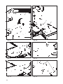
1
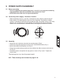
�������������� ��� ���������� ���������������������������������������� �������������������������������������������� ������������������������������������� CONTENTS 1. Safety instructions 2. General instructions/Dust and Noise 3. Power supply/Assembly 4. Functions/Transport 5. Operation 6. Maintenance/Repair 7. Troubleshooting 8. Warranty 9. Technical data 10. Standard-/Optional equipment 11. Illustrations 12. Wiring Diagram 13. Spare part list/Drawings 14. Conformity Declaration 15. Product marks 2 Original Manual: Norwegian 545904. Side 3 4 5 9 10 11 12 13 14 14 15 18 20 27 28 1.SAFETY INSTRUCTIONS. 1. This machine is designed and constructed by Ernex AS and has been submitted for test and found in conformity with the Machine Directive 2006/42/EF, 2006/95/EF and EN 1870-5: 2002. 2. The Health and Safety at Work etc. Act 1974 places duties on designers, manufacturers and suppliers to ensure that among other things: 1. articles supplied for use at work are, so far as is reasonably practicable, safe and without risks to health during setting, cleaning and maintenance and 2. persons supplied with the articles are provided with adequate information about the use for which they are designed and about conditions necessary to ensure that they will be safe and without risks to health. 3. These duties will apply to you if you re-supply the machine by way of sale, lease, hire or hire purchase. 4. Persons who install this machine for use at work have a duty under the Health and Safety at Work etc. Act 1974 to ensure, so far as is reasonably practicable, that nothing about the way in which it is installed makes it unsafe or a risk to health at all times during setting, use, cleaning and maintenance. This includes such aspects as correct assembly, electrical installation, construction of enclosures, fitting of guards and exhaust ventilating equipment. When installing this machine, consideration must be given to the provision of adequate lighting and working space. 5. This machine is supplied complete with all necessary safeguards to enable the user to comply with the Woodworking Machines Regulations 1974 and the Provision and use of Work Equipment Regulations 1992. Details of correct installation and use, together with guidance on fitting and proper adjustment of guards are described in this manual. ENG LISH 6. The Woodworking Machines Regulations place absolute legal duty on employers and employees to ensure that guards and the Provision and use of Work Equipment Regulations 1992 and any other safety devices are securely fitted, correctly adjusted and properly maintained. 7. Repairs and maintenance must only be undertaken by competent technicians. Ensure that all power supplies are isolated before maintenance work commences. Instructions for routine maintenance are included in this manual. 8. Machine operators must have received sufficient training and instructions as to the dangers arising in connection with the machine, the precautions to be observed and the requirements of the Woodworking Machines Regulations which apply, except where they work under the adequate supervision of a person who has a thorough knowledge and experience of the machine and the required safeguards. 9. Persons under the age of eighteen years must have successfully completed an approved HSE course of training before operating this machine at work, unless participating in a course of training under adequate supervision. (NB. This paragraph is only relevant to: circular sawing machines, any sawing machine fitted with a circular blade, any planing machine for surfacing which is not mechanically fed or any vertical spindle moulding machine). The saw can be used for sawing wood, plywood and chipboard. The saw must not be used on plasterboard, polystyrene and tarred paper (for roofing). WARNING: Safety equipment such as riving knife, blade guard and push sticks must not be removed, but have to be used! 3 2. GENERAL INSTRUCTIONS/DUST AND NOISE 2.1 General safety precautions • • • • • • • • • • • • • • • • IMPORTANT! According to the CE-regulations, adjustable rollertable must always be used. Ensure that there is adequate room around the saw. For best stability, place saw on a level and even surface. Keep sawtable, saw blade cover and area around saw free for off cuts and excessive sawdust. The working area should be well ventilated and a sawdust extractor or collector must be used. Use good lighting and adequate hearing and eyesight protection. When sawing longer pieces use the extra feed off rollertable or suitable support. Always lower top guard when sawing. Use push sticks when ripping small stock and when the distance between saw blade and rip fence is less than 120 mm (approx. 5"). Always switch motor off when adjusting blade or turntable angle. Lower saw blade when not in use. Always use riving knife. See section 6.2 for adjusting. Disconnect main cable when changing saw blade or performing other maintenance work. Use only carbide-tipped sawblade which is properly sharpened. Never use a cracked or deformed saw blade. Ensure that the saw blade cover plate is closed after saw blade has been cleaned and/or changed or if riving knife has been changed or adjusted. Worn aluminium edging strips in turntable should be replaced. Dust and Noise Dust and noise measurements have been performed for work with the materials and sawblades for which the machine is intended (see Section 1 Safety Instructions). Measurement uncertainty is related to local conditions and can vary with the saw blade/transmission characteristics. Follow the maintenance instructions (see Section 6 Maintenance/ Repair Ear protection must be used, and a dust mask is recommended For indoor use, the machine must be connected to an extractor that provides a minimum air speed of 30 m/s i.e. 1.8 kPa. 4 3. POWER SUPPLY/ASSEMBLY 3.1 Mains connection • Saws are supplied with standard plugs (only in the U.K.). Any extension cord being used should be a cable with a conductor cross-section of 2.5 mm2. • NOTE! Extension cords must have ground protection. 3.2 Connecting mains supply - direction of rotation • When connecting mains to a saw with a three-phase motor, check to see that the saw blade rotates in the right direction (away from the riving knife). The direction of blade rotation is indicated on the blade housing under the table. If the blade rotates in the wrong direction, two of the phases must be switched. This should be done by an electrician. Check also to see that blade is mounted correctly with regards to direction of rotation. 3P+N+ S2 T3 R1 N ENG LISH Kobl. 400V (5 pins) 3.3 Assembly • • • • Attach the saw to the base using the two mounting hooks (Fig.9). Check the riving knife regularly to ensure that it is positioned correctly (Fig. 1). Mount the handle to the elevation arm (Fig. 2). Screw the turntable locking handle into the nut below the table and secure with the locknut (Fig. 3). • Loosen the screws and position the top guard as shown in Fig. 4 and 5. Tighten the screws firmly. The drawings may vary from the present model. N.B! - These drawings can be found on page 15-18. 5 3.4 Assembling the adjustable infeed table • • • • • Fasten the brackets to the saw guide rail. Screw in all screws loosely. (Fig. 1) Fasten the guide rail to the brackets. Unscrew the stop screw B (Fig. 2). Ensure that the jaws of clamp C are open, and push the roller unit D into the guide rail; tighten stop screw B. Normally, it is not necessary to adjust the ball bearings on the roller unit but, if necessary, loosen the ball-bearing screws just below the unit, and adjust with screws E, so that the roller unit runs easily without wobbling. After adjustment, tighten the locknuts and the ballbearing screws. Pull the roller unit towards stop screw B. Adjust the distance between the saw table and the roller unit to about 15 mm. Use the support trestle L (Fig. 4) when assembling the infeed table F (Fig. 2). Affix the infeed table to the roller unit using screws and nuts G (do not screw too tightly). Adjust the screws H so that the roller unit and infeed table are in the same plane. Check using the rip fence. Tighten the locknuts. Using screws A (Fig.1), adjust the height of the roller unit so that it lies in plane with the turntable on the saw. 3.5 Assembling the rip fence • • • • Affix the fastening bracket C and the locking handle to the infeed table using nut E (Fig. 3). Lower the trestle L (Fig. 4), and push the fence into position. Raise the trestle. Rotate the turntable to 0°. Using a set square, adjust the guide rail so that the fence is at a 90° angle to the saw blade (Fig. 5). Fasten the fence so that the end-piece of the fence is 3 mm from the saw blade and the scale displays the correct value (Fig. 6). Rotate the turntable to 90°, and pull the fence in toward the saw blade. Adjust the indicator P so that it points to 0 on the guide rail (Fig. 7). Adjust the legs of the trestle L (Fig. 4) so that both ball bearings rest against the trestle. 3.6 Assembling the telescopic extension • • • Remove the end stop from the rip fence and push the telescopic extension R into the fence. Put the end stop in the telescopic extension (Fig. 9). Attach the locking screw Q to the telescopic extension (Fig. 8). Attach the bracket S to the telescopic extension (Fig. 9). 3.7 Assembling the length stop • Mount the length stop T edge-to-edge with the aluminium end of the telescopic extension (Figs. 8 and 9). 3.8 Assembling the fixed table • Assemble as illustrated in Figs. 10 and 11. • • • • • • 6 Montering av regulerbart rullebord Mounting of adjustable table Montage des Schieberollentischs C G M6x45 M8x16 A M10x16 M8x16 H D E Fig. 1 C F E B G M8x35 M8x16 Fig. 2 Fig. 3 L Fig. 4 Fig. 5 7 3mm P Fig. 6 Fig. 7 T T Q M8x16 Fig. 8 S Fig. 9 Montering av fast Rullebord Mounting of fixed table Montage des festen Rollentischs M8x30 M8 Fig. 10 8 Fig. 11 R 4. FUNCTIONS/TRANSPORT 4.1 On/Off switch A green ON button and a red OFF button are located on the saw’s front panel (Fig. 6). The ON button is equipped with a lockable cover. The saw is provided with a low-voltage cutout as well as overload protection which disconnects the power supply under overload conditions to prevent motor damage. If this occurs, let the motor cool down for a few minutes, after which it will be ready to run again. Try to avoid overloading motor. 4.2 Raising and lowering saw blade Free the elevation arm by loosening the elevation locking clamp (Fig. 7), whereupon the blade may now be raised and lowered. The saw blade may be locked into position at any height by retightening the locking clamp. 4.3 Tilting the saw blade The saw blade must be in low position before adjusting bevel angle. This adjustment is made by loosening the tilt locking clamp and pressing the tilt preset. The saw blade may now be tilted to any bevel angle between 0° and 45° (Fig. 8), with the angle indicated on the curved scale. Tighten the tilt locking clamp when finished. 4.4 Turning turntable The turntable may be rotated horizontally in either direction and set at any cutoff angle. Loosen the turntable by pushing locking handle to the left (Fig. 9). Turn the turntable to the desired cutoff angle by means of the elevation arm (scale on table top indicates cutoff angle). Lock the turntable by pushing the locking handle to the right. Frequently used angles (90°, 45°, 30°, 22,5°, 15° and 0°) are preset. IMPORTANT! To prevent personal injury or damage to saw, the motor must be shut off while making any saw blade adjustments. When lifting using a crane, attachment straps can be placed around the legs. Wheels can be supplied as an option. 9 5. OPERATION 5.1 Crosscuts • Set cutting angles as described in section 4.4 (or 4.3 if applicable). • Move long fence in close to saw blade slot and lock with fence locking clamp J (Fig. 10). • Adjust top guard U height to about 5 mm (3/8") above thickness of workpiece, and lock with top guard locking clamp V (Fig. 10). 5.2 Ripping • Rotate turntable to the 90° mark, setting it parallel with the long fence (Fig. 9,11 and 12), and lock as described in section 4.4. • Adjust bevel angle if desired, as described in section 4.3 (Fig. 8 and 13). • Raise saw blade to slightly higher than thickness of workpiece and lock as described in section 4.2 (Fig. 7). • Set long fence to the desired ripping width, and lock with roller table locking clamps C on Fig. 14 and 15. • Loosen top guard locking clamp V, allowing the leading edge of the top guard to rest on the table top (Fig. 11). This will permit the workpiece to lift the top guard and slide underneath as it is fed into the saw. • Start the motor and push the workpiece along the long fence and into the saw blade (Fig.11 and 12). IMPORTANT! Always use riving knife. Make sure that it is positioned correctly and that it is of the correct thickness. See section 6.2. Feed the workpiece at an even rate, reducing the pressure if the motor starts working hard (this will be quite noticeable). This protects the motor and yields a cleaner cut. 5.3 Angled crosscuts • Set turntable to desired angle (Fig. 16). • Adjust long fence and carry out cutting operation as described in section 5.1. 5.4 Bevelled and angled crosscuts • Set turntable to desired cutoff angle. • Tilt and lock sawblade in desired bevel angle. • Adjust long fence appropriately (Fig.17). 5.5 Cutting tongue and groove • Rotate turntable to the 90° mark, setting the sawblade parallel with the long fence, and lock as described in section 4.4. • Adjust sawblade height (depth of groove). • Set feed table to desired position and lock. • Feed the workpiece along the long fence. • For a wider groove, move feed table slightly offset and repeat the last step (Fig.18). 10 6. MAINTENANCE/REPAIR IMPORTANT! Make sure power supply is disconnected while performing maintenance operations. A minimum of maintenance is required to ensure satisfactory performance and a long service life. • Lubricate moving parts, linkages and the bearings carrying the turntable at regular intervals. • Check all screws and nuts regularly for tightness. • Keep saw and saw blade housing free from sawdust. Pay particular attention to motor ventilation openings and cooling ribs. • Keep saw blade clean and in order. Replace blade if there are any cracks or missing teeth. Remove resin deposits with a suitable cleaning fluid. 6.1 Replacing saw blade Disconnect plug. Lower saw blade completely. Raise plate B and open cover by removing screws A in front (Fig. 19). Immobilize arbor by inserting a screwdriver through the hole in the arbor and cover, and loosen arbor screw with an 17 mm (11/16") wrench (Fig. 20). Remove washer and saw blade. NOTE! Arbor screw has left-hand thread. • Replace saw blade in reverse order. Remember direction of rotation. 6.2 Replacing/adjusting riving knife • Pull out plug and open cover as described in section 5.1. • Loosen attachment screw (Fig. 21) and lift out riving knife (for replacing knife). • Replace riving knife in reverse order of removal. Always use a knife that is 0.2 mm (0.008") thicker than sawblade base. • Position riving knife as illustrated in Fig. 1, and tighten attachment screw. 6.3 Replacing drive belt • Pull out plug and remove saw blade and riving knife as described in sections 6.1 and 6.2. • Remove cover by removing the four attachment screws with the motor and sawblade first raised and than lowered (Fig. 22). • Work belt off pulleys using a screwdriver (Fig. 23). • Replace belt in reverse order. 6.4 Turntable clamp adjustment • Loosen clamp, Fig. 24. • Loosen locknut P. • Screw slotted screw O in or out as necessary until turntable clamp locks firmly when handle is in locked position. 11 ENG LISH • • • • REPAIR Routines at repair: *The machine must only be repaired by qualified electricians or authorised service workshops. Testing the brakes: *The brake for the saw blade rotation should be tested regularly. The stop-time must be max. 10 sec. Start/stop the saw 10 times in a row and check the stop-time. 7. TROUBLESHOOTING The saw does not start: The saw vibrates and is weak: * check that the blade box below the saw table does not contain chips and sawdust * check that the toothed belt is undamaged * check the spindle * check the blade for eccentricity, and that all the teeth are whole and sharp The saw blade is heavy to lift and does not go down completely: * check that nothing is stuck in the blade box * check the power supply * do not use the cable with several machines at the same time * check that the cable is not too long, and that the cross-section is not too small * contact an electrician 12 8. WARRANTY SERVICE Notwithstanding any statutory requirements, Ernex AS provide warranty in accordance with the legislation of the customer‘s own country of residence, but in all cases for a minimum of 3 years, except for electrical parts which still has a 1-year warranty commencing from the date on which the machine is sold to the end user. Ernex AS/The importer promise to repair, or at our option, replace with like grade and quality any product determined to be faulty due to the failure of parts, material or workmanship. The warranty covers defects in material and/or workmanship only. When making a claim under the warranty, proof of purchase bearing the original date of purchase must be submitted. The repairs under warranty may only be carried out by Ernex AS, or by authorized Ernex warranty service agents or the importer. The warranty will not apply in cases of: - incorrect use, overloading of the machine or fitting non-approved accessories - use of force, damage caused by external influences, or foreign bodies - damage caused by non-observance of the instructions for use, such as connection to an unsuitable mains supply or voltage or non-compliance with the installation instructions - normal wear and tear The warranty also does not cover machines which have been partially or completely dismantled. 13 9. TECHNICAL DATA Norsaw 805 Manufacturer: Model: Table: Height w/o base: Height w/base: Transp. height: Weight: Sawblade: Riving knife: Cutting height: Motor: Motor speed: Spindle speed: Peripheral speed: Cable dimension: Fuse: Switch: Drivebelt: Noise as per DIN 45635: -certification: Ernex AS, Norway. Norsaw 805. 440 mm x 530 mm. 440 mm. 850 mm. 560 mm. 48 kg. Carbide-tipped, Z=30. Diam. 204 mm. Arbor hole 30 mm. (USA 31.75 mm) Kerf width 2,8 mm. Blade thickness 1,8 mm. Hardened steel, standard thickness 2,2 mm. 70 mm at 90° (vertical). 48 mm at 45° (tilted). 1.1 kW 110 V/50 Hz single-phase. 1.1 kW 230 V/50 Hz single-phase. 1.1 kW 400 V/50 Hz three-phase. 1.0 kW 120 V/60 Hz single-phase. 2800 rpm. (USA 3360 rpm) 3600 rpm. (USA 4320 rpm) 38.5 m/s with standard blade. Single phase 3 x 1.5 mm2. Three phase 5 x 1.5 mm2. 10A time-lag fuse (230V), 16 A (110 V/120 V). On/Off with overload and low-voltage cutout. Single toothed belt. No-load: 79,0 dB. Loaded: 84,0 dB. Certified by Dansk Teknologisk Institut, Aarhus. Identification number: 0396, approval certificate number TI-09-MD-0309. 10. STANDARD EQUIPMENT • Base • Carbide-tipped blade • Push sticks OPTIONAL EQUIPMENT • • • • • Infeed table with fence and length stop* Fixed table Wheels Telescopic extension Sawdust extractor. * In accordance with CE-regulations the adjustable infeed rollertable must always be used. 14 Fig. 1 Fig. 2 Fig. 3 Fig. 4 Fig. 5 Fig. 6 Fig. 7 Fig. 8 ENG LISH Min 3 mm Max Max 8 mm 2 mm 15 V U C J Fig. 9 Fig. 10 Fig. 11 Fig. 12 V Fig. 13 16 Fig. 14 U C C Fig. 15 Fig. 16 Fig. 17 Fig. 18 B A A Fig. 19 Fig. 20 Fig. 21 Fig. 22 17 P O Fig. 23 Fig. 24 805 - 230V/1 ELEKTRISKKOPLINGSSKJEMA L N PE sw 01 sw sw 0 1 43 33 23 13 a 44 34 24 14 b 02 br 01 02 GehaeuseK570. Schuetz E3250. 230V 1-fas 18 b1 ws gn/ge 19 34 33 24 23 14 13 b a Kleinschuetz E3250 3s-1oe mit Vorschaltoeffner. Bremsplatine Nr. 408200. Gehaeuse K500. Gehaeuse K700 04 01 42 41 110V 1-fhasig 01 03 04 05 1 0 L N PE ws br b1 gnge 03 05 20 34 33 24 23 14 13 b a Kleinschuetz E3250 3s-1oe mit Vorschaltoeffner. Bremsplatine Nr. 408200. Gehaeuse K500. Gehaeuse K700 04 01 42 41 400V Drehstrom 01 03 04 05 1 0 br sw b1 03 L1 L2 L3 N PE gnge 05 Ernex AS Pos. 1 2 3 5 6 7 8 9 10 11 12 13 14 15 16 17 18 19 20 21 22 23 24 25 26 27 28 29 30 31 32 33 34 35 36 37 38 39 41 42 43 44 45 46 47 48 49 50 51 52 53 54 55 56 57 Spare Part List Gjerde 805 Art.No. Text 745 107 745 120 745 029 745 683 745 530 745 260 745 434 745 056 745 441 745 291 745 442 745 216 745 643 745 060 745 064 745 072 745 146 745 126 745 161 745 452 745 152 745 081 745 153 745 054 745 057 745 037 745 069 745 114 745 055 745 117 745 147 745 033 745 051 707 019 745 197 745 210 745 257 745 043 745 191 745 192 745 194 745 195 745 023 745 229 745 228 745 224 745 027 745 350 745 035 745 025 745 026 745 392 745 067 745 686 745 036 Saw base Saw frame End caps (4) Screws Sawtable top Turntable lock compl. Turntable pos. compl. Locking handle Spring stud Switch cover Turntable Packing strips compl. Bearings f/turntable (4) Mounting hinges (2) Housing Screw f/blade cover Blade cover, lower Hinge plate Spring f/hinge plate Tilting scale Tilting set compl. Spring f/tilting Angle indicator Tilt locking clamp Elevation spring Support hooks f/saw base (2) Elevation pillar Elevation arm Handle Jointed arm Connecting arm Elevation slider Locking clamp f/height adjustment Hook f/push stick Upper guard compl. Upper guard (04/10-) Upper guard support (04/10-) Locking clamp f/upper guard (04/10-) Motor w/switch & brake 230V/1** Motor w/switch & brake 400V/3* Motor w/switch & brake 110V/1** Motor 120V/1-60Hz USA Bearings f/motor compl. (4) Fan cover Fan Fan f/motor w/brake Motor pulley Spindle compl. Spindle w/clamp Bearings f/spindle (3) Pulley wheel f/spindle Housing f/spindle Collar nut Arbor nut M10 x 20 links Blade retaining plate 58 59 60 61 62 63 64 65 66 66 67 72 73 74 75 77 78 79 80 81 82 83 84 85 86 87 89 130 131 145 745 206 745 208 745 168 745 456 745 040 745 041 745 217 745 123 745 028 745 042 745 268 708 744 744 921 745 204 745 580 745 991 745 992 745 454 744 904 744 911 745 455 745 410 745 422 745 185 745 443 745 187 745 223 745 221 745 993 745 099 Capacitor 30 MF -N Capacitor 110 MF -UK Capacitor clamp 110V Capacitor clamp f/230V Riving knife 2.2 mm - Std. Riving knife 2.5mm Clamps f/riving knife Belt cover Toothed belt Tooth belt w/steelcord Mounting bracket f/switch Electronic card 230V/1-3 ph. K&B Switch w/brake 120V/1-60Hz K&B 00Switch assy. 110/120V/1 ex br.** 86-95 Switch 230V/1 ex brake K&B** 96-98 Switch 400V/3 w/brake K&B** 95Switch 110V/1 w/brake K&B** (95-) Switch 230V/1 ex brake Tr.** 86-96/98Switch button, green K&B Switch button, red K&B Terminal box Hann. Main lead w/plug Wrench 10 x 13 mm (open ended) Combined wrench 17mm Allen key Screwdriver 5x125 mm Relay 110/120V (w/o brake) Relay 230/400V Tripus/K&B Relay 110V K&B (w/brake) Push stick * Before -1986 ** After 1986- 60 mm opening in front 67 mm " Pos. 74 - 745204 Pos. 75 - 745580 Pos. 77 - 745991 Pos. 78 - 745992 Pos. 79 - 745454 Tripus 110V 86-95 K&B 230V(2 cables) K&B 400V 1995K&B 110V 1995Tripus 230V 86-96/98- (1 cabel) 2011 21 22 23 Ernex AS Pos. 1 2 3 4 5 6 7 8 9 10 11 13 14 15 16 17 18 19 20 21 22 23 24 25 26 27 28 29 30 31 32 33 34 35 36 37 38 39 40 41 42 43 47 48 51 53 57 58 59 60 61 62 63 64 65 Spare part list Rollertables/Accessories 805 Art.No. Text 745 921 772 728 707 879 772 878 745 376 745 310 745 926 745 922 745 746 745 901 745 927 745 919 745 965 745 923 745 685 745 961 745 960 745 764 745 929 720 075 745 959 745 621 707 710 707 711 745 583 745 622 745 763 745 925 745 817 745 917 745 958 745 377 745 966 772 726 772 734 745 613 745 612 745 584 701 503 745 671 745 654 945 490 720 074 708 608 707 604 707 601 945 695 745 963 745 962 745 689 945 870 745 964 772 746 772 733 745 868 Frame w/rollers Roller compl. Nylon bearings (2) Plug Support trestle compl. Trestle leg Guide bar compl. (91-) Brackets w/screws f/guide bar (2) (91-) Measure f/guide bar End plug f/guide bar Roller box compl. (91-) Guide roller w/bearings (4) Caster w/screw f/roller box (1) End plug f/trestle Adjustment bolt M8x35 Indicator f/roller box Locking system f/roller box compl. Locking clamp M8x14 Handle f/r.box locking Plastic sleeve 25x5 (93-99) Fixing brackets f/roller box Length stop compl. Short work support compl. Roller Locking clamp f/guide fence M8x30 Long fence compl. Measure f/alu.fence Trestle compl. Trestle, upper part , fixed Trestle legs f/fixed table R/L Hinge w/screws Guide bolt f/long fence Bracket f/long fence Sub-carrier compl. Ball bearings f/sub-carrier (2) Telescope extension compl. End section f/telescope Locking clamp f/telesc. extension Angle fence compl. Scale Spacer plate f/guide fence Angle fence compl. (small) Plastic sleeve 25x8 mm Hood w/dustconnector Suction connector w/rivets Adjusting bar (2) Upper guard compl. Guard arm Guard bracket Adjusting bracket Option-fixing assy. compl. Assembly f/fixed table Fixing assy. f/fixed table Trestle leg single Crosspiece f/table 66 67 68 82 140 141 142 143 772 747 745 712 745 180 745 413 772 727 745 624 745 462 745 618 Board support Board support retainer Bracket f/fixed table Locking screw “special” M6x13 Locking clamp M10x30 Short fence End cap front Blanking plug 2011 24 25 26 Gjerdesagen: 805-12-/16-/2003 SAMSVARSERKLÆRING CONFORMITY DECLARATION KONFORMITÄTSERKLÄRUNG KONFORMITETSINTYG DICHIARAZIONE DI CONFOMITA Fabrikant - Manufacturer - Hersteller - Produttore: Ernex AS Adresse - Adress - Anschrift - Indirizzo: 1792 Tistedal Erklærer herved at : Maskin: Mod.: Nr.: ………………… Som er omfattet av denne erklæring, er fremstilt i overensstemmelse med Rådets direktiv 2006/42/EF, 2006/95/EFog EN 1870-5:2002. Det bemyndigede organ: Dansk Teknologisk Institut, Århus, identifikasjons Nr.: 0396, har prøvet denne maskinen i følge typeattest Nr. TI-09-MD-0309, TI-09-MD-0310, TI-09-MD-0312 og TI-09-MD-0313. We hereby declare that: Machine: Mod.: Nr.: ………………… Which is covered by this declaration is manufactured in conformity with the Commission’s instructions 2006/42/EF, 2006/95/EF and EN 1870-5:2002. The notified body: Dansk Teknologisk Institut, Aarhus, identification No.: 0396, has examined this machine according to approval certificate No. TI-09-MD-0309, TI-09-MD-0310, TI-09-MD-0312 and TI-09-MD-0313. Erklärt hiermit : Die Maschine: Mod.: Nr.: ………………… Die diese Erklärung betrifft wurde in konformität mit den Richtlinien vom Rat der Europäischen Gemeinschaften 2006/42/EF, 2006/95/EF u. EN 1870-5:2002. Notizierte Stelle: Dansk Teknologisk Institut, Århus, Identifikations Nr.: 0396, hat diese Maschine geprüft, Bescheinigung durch das Typattest Nr. TI-09-MD-0309, TI-09-MD-0310, TI-09-MD-0312 u. TI-09-MD-0313 Försäkrar härmed att : Maskin: Mod.: Nr.: ………………… Vilken innefattas i denna deklaration, är tillverkad i överenstämmelse med Maskindirektiv 2006/42/EF, 2006/95/EF och EN 1870-5:2002. Bemyndigat organ: Dansk Teknologisk Institut, Aahus, identifikations Nr.: 0396, vilket prövat denna maskin enl. Provningscertifikat Nr. TI-09-MD-0309, TI-09-MD-0310, TI-09-MD-0312 och TI-09-MD-0313. Con la presente si dichiara che la : Macchina: Mod.: N.: ………………… Oggetto della presente dichiarazione è prodotta in confomità alla direttiva della Commissione 2006/42/EF, 2006/95/EF e EN 1870-5:2002. L`ente notificato: Dansk Teknologisk Institut, Aarhus, N. di identificazione: 0396, ha esaminato il macchinario come da certificato di approvazione N. TI-09-MD-0309, TI-09-MD-0310, TI-09-MD-0312 e TI-09-MD-0313. Tistedal, ……………………. Jan Håkon Hansen ………………………………. Skjema nr. 134 27 15. PRODUCT MARKS 28 545603-01/11 Importers: Sverige/Sweden: Aspelin Motek AB Fabriksgatan 11, Box 10, SE-63102 Eskilstuna Tel: +46 16 200 2000, Fax: +46 16 153029 E-mail: [email protected] www.motek.se Sverige/Sweden: Luna Verktyg & Maskin AB Sandbergsvägen 1, SE-441 80 Alingsås Tel.: +46 322 606000, Fax: +46 322 606443 E-mail: [email protected] www.luna.se Danmark/Denmark: Junget A/S Sigma 3, Søften, DK-8382 Hinnerup Tel: +45 893 65500, Fax: +45 893 65555 E-mail: [email protected] www.junget.dk Finland/Finland: Oy Mechelin Co. AB Mekaanikonkatu 13, SF-00880 Helsinki Tel: +358 9755151, Fax: +358 975515252 E-mail: [email protected] www.mechelin-company.fi Island/Iceland: Bjørn Gudmundsson & Co. Laugavegi 29, IS-101 Reykjavik Tel.: +354 124321, Fax: +354 5624346 E-mail: [email protected] www.brynja.is Holland/Netherland: Gjerde B.V. Mors 9, NL-7151 MX Eibergen Tel: +31 545 472855, Fax: +31 545 472865 E-mail: [email protected] www.gjerde.nl Manufacturer: Tyskland/Germany: Hüllinghorst Maschinenhandel GmbH & Co. KG Höfeweg 70, DE-33619 Bielefeld Tel: +49 5219110612, Fax: +49 5219110699 E-mail: [email protected] www.huellinghorst.de Tyskland/Germany: Eumacop eG Johann-Friedrich-Böttger Str. 21, DE-63322 Rödermark Tel: +49 607489170, Fax: +49 6074891717 E-mail: [email protected] Estland/Estonia: AS Nava Peterburi Tee 56 B, EE-11415 Tallinn Tel.: +372 621 1360, Fax: +372 621 1361 E-mail: [email protected] www.nava.ee Ungarn/Hungary: Csiba Kft. Rohonco u., PF. 130, H-9730 Köszeg Tel: +36 943 62731, Fax: +36 943 61384 E-mail: [email protected] www.csiba.hu Latvia/Latvia: MekoTex SIA Pãrslas St. 3/5, LV-1002 Riga Tel.: +37 17616018, Fax: +37 17616019 E-mail: [email protected] www.mekotex.lv Ernex AS 2011 Bjørnstadgt. 7, N-1792 Tistedal, Norway. Tlf. +47-69 17 83 30, Fax +47-69 17 83 60 E-mail: [email protected] - www.ernex.no 29