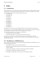
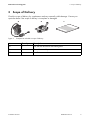
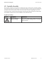
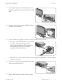
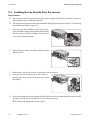
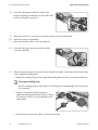
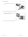
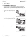
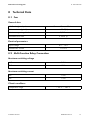
1
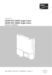
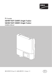
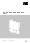
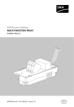
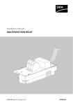
Accessories for SMA Inverters
Fan Retrofit Kit FANKIT01-10
Installation Manual
FANKIT01-IA-en-12 | IMEN-FANK-TL21 | Version 1.2
EN
SMA Solar Technology AG
Table of Contents
Table of Contents
1 Information on this Document. . . . . . . . . . . . . . . . . . . . . . . . . . . 5
2 Safety . . . . . . . . . . . . . . . . . . . . . . . . . . . . . . . . . . . . . . . . . . . . . . 7
2.1 Intended Use . . . . . . . . . . . . . . . . . . . . . . . . . . . . . . . . . . . . . . . . . . . . 7
2.2 Qualifications of Skilled Persons . . . . . . . . . . . . . . . . . . . . . . . . . . . . . 7
2.3 Safety Precautions . . . . . . . . . . . . . . . . . . . . . . . . . . . . . . . . . . . . . . . . 8
3 Scope of Delivery . . . . . . . . . . . . . . . . . . . . . . . . . . . . . . . . . . . . . 9
4 Product Description . . . . . . . . . . . . . . . . . . . . . . . . . . . . . . . . . . 10
4.1 Fan Retrofit Kit . . . . . . . . . . . . . . . . . . . . . . . . . . . . . . . . . . . . . . . . . . 10
4.2 Controller assembly . . . . . . . . . . . . . . . . . . . . . . . . . . . . . . . . . . . . . . 11
5 Installation . . . . . . . . . . . . . . . . . . . . . . . . . . . . . . . . . . . . . . . . . 12
5.1 Installation Area Overview . . . . . . . . . . . . . . . . . . . . . . . . . . . . . . . . 12
5.2 Removing the Multifunction Relay . . . . . . . . . . . . . . . . . . . . . . . . . . . 12
5.3 Installing the Fan Retrofit Kit in the Inverter . . . . . . . . . . . . . . . . . . . . 14
6 Connecting the Fan Retrofit Kit . . . . . . . . . . . . . . . . . . . . . . . . . 15
7 Disassembling. . . . . . . . . . . . . . . . . . . . . . . . . . . . . . . . . . . . . . . 18
7.1 Disassembling the Fan Retrofit Kit . . . . . . . . . . . . . . . . . . . . . . . . . . . 18
7.2 Disposing of the Fan Retrofit Kit. . . . . . . . . . . . . . . . . . . . . . . . . . . . . 20
8 Technical Data . . . . . . . . . . . . . . . . . . . . . . . . . . . . . . . . . . . . . . 21
8.1 Fan. . . . . . . . . . . . . . . . . . . . . . . . . . . . . . . . . . . . . . . . . . . . . . . . . . . 21
8.2 Multi-function Relay Connection . . . . . . . . . . . . . . . . . . . . . . . . . . . . 21
9 Contact . . . . . . . . . . . . . . . . . . . . . . . . . . . . . . . . . . . . . . . . . . . . 22
Installation Manual
FANKIT01-IA-en-12
3
Table of Contents
4
FANKIT01-IA-en-12
SMA Solar Technology AG
Installation Manual
SMA Solar Technology AG
1 Information on this Document
1 Information on this Document
Validity
This manual is valid for the fan retrofit kit of type "FANKIT01-10".
Target Group
This document is for skilled persons. Only qualified personnel with the appropriate skills are allowed
to perform the tasks described in this manual (see Section 2.2 "Qualifications of Skilled Persons",
page 7).
Additional Information
For further information, see www.SMA-Solar.com:
Document title
Document type
SUNNY BOY 2500TL Single Tracker
SUNNY BOY 3000TL Single Tracker
Installation manual
SUNNY BOY 3000TL/3600TL/4000TL/5000TL
Installation manual
Multi-Function Relay and OptiTrac Global Peak
Technical description
Symbols
Symbol
Explanation
Indicates a hazardous situation which, if not avoided, will result in death
or serious injury
Indicates a hazardous situation which, if not avoided, could result in death
or serious injury
Indicates a hazardous situation which, if not avoided, could result in minor
or moderate injury
Indicates a situation which, if not avoided, can result in property damage
Information that is important for a specific topic or objective,
but is not safety-relevant
☐
Indicates a requirement for meeting a specific goal
☑
Desired result
✖
A problem that might occur
Installation Manual
FANKIT01-IA-en-12
5
1 Information on this Document
SMA Solar Technology AG
Typographies
Typography
"light"
Usage
• Display messages
• Parameter
Example
• The inverter switches to
"Balanced" mode.
• Connections
• Slots
bold
• Elements to be selected
• Set the Fan Test parameter to 1.
• Elements to be entered
6
FANKIT01-IA-en-12
Installation Manual
SMA Solar Technology AG
2 Safety
2 Safety
2.1 Intended Use
The fan retrofit kit consists of a fan and a controller assembly for the fan. The fan provides the inverters
with additional cooling during high ambient temperatures. The controller assembly controls the fan.
The fan retrofit kit may only be used with the following inverters:
• SB 2500TLST-21
• SB 3000TLST-21
• SB 3000TL-21
• SB 3600TL-21
• SB 4000TL-21
• SB 5000TL-21
• WB 3000TL-21
• WB 3600TL-21
• WB 4000TL-21
• WB 5000TL-21
Alternative uses not expressly recommended by SMA Solar Technology AG are not permitted.
For safety reasons, it is not permitted to modify the product or install components that are not explicitly
recommended or distributed by SMA Solar Technology AG for this product.
The enclosed documentation is an integral part of this product.
• Read and observe the documentation.
• Keep the documentation in a convenient place for future reference.
Only use the fan retrofit kit in accordance with the specifications provided in the enclosed
documentation. Any other use may result in personal injury or property damage. Also observe the
relevant inverter manual.
2.2 Qualifications of Skilled Persons
The work described in this document must only be performed by skilled persons. Skilled persons must
have the following qualifications:
• Knowledge of how an inverter works and is operated
• Training in how to deal with the dangers and risks associated with installing and using electrical
devices and plants
• Training in the installation and commissioning of electrical devices and plants
• Knowledge of all applicable standards and directives
• Knowledge of and adherence to this document and all safety precautions
Installation Manual
FANKIT01-IA-en-12
7
2 Safety
SMA Solar Technology AG
2.3 Safety Precautions
Electric Shock
High voltages that can cause fatal electric shocks are present in the live components of the inverter.
• Prior to performing any work on the inverter, disconnect the inverter from any voltage sources
(see inverter installation manual).
Electrostatic Discharge
By touching electronic components, you can damage or even destroy the inverter through electrostatic
discharge.
• Earth yourself before touching any components.
8
FANKIT01-IA-en-12
Installation Manual
SMA Solar Technology AG
3 Scope of Delivery
3 Scope of Delivery
Check the scope of delivery for completeness and any externally visible damage. Contact your
specialist dealer if the scope of delivery is incomplete or damaged.
A
Figure 1:
B
C
Components included in scope of delivery
Item
Quantity
Description
A
1
Fan with fan enclosure and cable gland
B
1
Controller assembly
C
1
Installation manual
Installation Manual
FANKIT01-IA-en-12
9
4 Product Description
SMA Solar Technology AG
4 Product Description
4.1 Fan Retrofit Kit
The fan retrofit kit consists of a fan and a controller assembly for the fan. The fan provides the inverters
with additional cooling during high ambient temperatures. The controller assembly controls the fan.
D
A
B
C
G
Figure 2:
F
Structure of the fan retrofit kit
Item
Description
A
Fan with fan enclosure
B
Cable gland with nut
C
Plug
D
Fan connection
E
Multi-function relay terminals
F
Controller assembly
G
Screw
10
E
FANKIT01-IA-en-12
Installation Manual
SMA Solar Technology AG
4 Product Description
4.2 Controller Assembly
The controller assembly controls the fan. A multi-function relay is placed on the controller assembly.
The multi-function relay is for switching on and off a fault indicator or another external load based on
parameters and measured values of the inverter (for further information regarding the use of the
multi-function relay, see the Technical Description "Multi-Function Relay and OptiTrac Global Peak"
and installation manual of the inverter available at www.SMA-Solar.com).
Symbol on Product
Symbol
Installation Manual
Designation
Explanation
Warning regarding
dangerous voltage
The product operates at high voltages. All work may
only be performed by skilled persons in accordance
with this manual.
FANKIT01-IA-en-12
11
5 Installation
SMA Solar Technology AG
5 Installation
5.1 Installation Area Overview
D
C
Figure 3:
B
B
A
Installation area in the inverter with the lower enclosure lid open and the display flipped up
Item
Description
A
Cable routes
B
Enclosure openings for the connection of the fan retrofit kit
C
Installation location for the controller assembly
D
Enclosure opening for the fan along with the fan enclosure
5.2 Removing the Multi-Function Relay
If a multi-function relay is pre-installed, the installation area of the controller assembly is blocked.
Before installing the fan retrofit kit, the multi-function relay must be removed according to the following
procedure.
1. Disconnect the inverter from voltage sources and open it (see inverter installation manual).
2. If the multi-function relay is assigned, disconnect the supply voltage to the multi-function relay
and ensure that the device cannot be reconnected.
12
FANKIT01-IA-en-12
Installation Manual
SMA Solar Technology AG
5 Installation
3. Press the locking levers of the left-hand socket on
the display outwards and remove the ribbon cable
plug.
4. Loosen the screw on the display and flip the display
up until it clicks into place.
1
2
5. If the terminals are assigned, remove the connection cable from the inverter:
• Flip up the terminals and pull out the insulated
wire. Hint: Note down the order of the
connected insulated wires. The connection to
the multi-function relay on the controller
assembly will be easier this way.
• Remove the connection cable from the inverter through the cable gland. To do this, slightly
loosen the swivel nut.
6. Loosen the screw on the pre-installed multi-function
relay using an Allen key AF 3.
7. Remove the multi-function relay from the inverter.
Installation Manual
FANKIT01-IA-en-12
13
5 Installation
SMA Solar Technology AG
5.3 Installing the Fan Retrofit Kit in the Inverter
Requirements:
☐ The inverter must be disconnected from the power supply and the lower enclosure lid must be
opened (see inverter installation manual).
☐ The multi-function relay must be removed and the display flipped up (see Section 5.2 "Removing
the Multifunction Relay", page 12).
1. Place the controller assembly in the inverter and
push the ribbon cable upwards behind the display.
The key of the controller assembly must fit into the
cut-out of the display retainer.
2. Fasten the screw of the controller assembly with an
Allen key AF 3.
3. Remove the cover of the enclosure opening for fan enclosures.
4. Insert the fan with fan enclosure in the enclosure
opening. The arrow on the fan enclosure must face
the display.
5. Route the locking tabs on the right-hand side of the fan enclosure underneath the enclosure wall
and press the fan with fan enclosure in the enclosure opening.
☑ The left-hand locking tabs lock into place.
14
FANKIT01-IA-en-12
Installation Manual
SMA Solar Technology AG
6 Connecting the Fan Retrofit Kit
6 Connecting the Fan Retrofit Kit
1. Remove the filler-plug from the right-hand enclosure
opening.
Storing the filler-plug
Store the filler-plug in a safe place. The filler-plug is needed again if the fan retrofit kit is
removed (see Section 7.1 "Disassembling the Fan Retrofit Kit", page 18).
2. Unscrew the cable gland from the left-hand
enclosure opening. To do this, loosen the inner
counter nut.
3. Insert the cable gland in the right-hand enclosure
opening and fasten it along with the counter nut
from inside.
4. After the swivel nut with sealing plug is unscrewed, screw the swivel nut with sealing plug on the
cable gland.
5. Fasten the swivel nut hand-tight.
6. Unscrew the counter nut from the provided cable gland of the fan cable.
7. Insert the fan cable through the left-hand enclosure opening into the inverter from outside.
Installation Manual
FANKIT01-IA-en-12
15
6 Connecting the Fan Retrofit Kit
SMA Solar Technology AG
8. Insert the cable gland of the fan cable in the
enclosure opening and fasten it to the inside of the
enclosure using the counter nut.
9. After the swivel nut is unscrewed, screw the swivel nut on the cable gland.
10. Fasten the swivel nut hand-tight.
11. Ensure that the fan cable is securely attached.
12. Insert the fan plug in the fan connection of the
controller assembly.
13. If the multi-function relay is to be used on the controller assembly, connect the multi-function relay
via the right-hand cable gland.
• Remove the sealing plug from the right-hand cable gland. For that, unscrew the swivel nut.
Storing the sealing plug
Store the sealing plug in a safe place. The sealing plug is needed again if the fan retrofit
kit is removed.
• Insert the connection cable through the
right-hand cable gland into the inverter. In doing
so, fasten the swivel nut only hand-tight on the
cable gland.
• Ensure that the connection cable is securely positioned.
16
FANKIT01-IA-en-12
Installation Manual
SMA Solar Technology AG
6 Connecting the Fan Retrofit Kit
• Flip up the terminals and insert the insulated
wires.
1
2
14. Fold down the display and fasten the screw hand-tight.
15. Insert the ribbon cable in the left-hand socket on the
display until it clicks into place.
16. Close the inverter (see inverter installation manual).
Installation Manual
FANKIT01-IA-en-12
17
7 Disassembling
SMA Solar Technology AG
7 Disassembling
7.1 Disassembling the Fan Retrofit Kit
1. Disconnect the inverter from voltage sources and open it (see inverter installation manual).
2. If the multifunction relay is assigned, disconnect the supply voltage to the multi-function relay
and ensure that the device cannot be reconnected.
3. Wait for the fan to stop rotating.
4. Press the locking levers of the left-hand socket on
the display outwards and remove the ribbon cable
plug.
5. Loosen the screw on the display and flip the display
up until it clicks into place.
1
2
6. Release and remove the fan plug.
2
1
18
FANKIT01-IA-en-12
Installation Manual
SMA Solar Technology AG
7 Disassembling
7. If the terminals are assigned, remove the connection cable from the inverter:
• Flip up the terminals and pull out the insulated
wires. Hint: Note down the order of the
connected insulated wires to make it easier to
reconnect them.
• Remove the connection cable from the inverter through the cable gland. Unscrew the swivel
nut to do so.
• Insert the sealing plug in the right-hand cable gland and screw the swivel nut hand-tight onto
the cable gland (see Section 6 "Connecting the Fan Retrofit Kit", page 15).
8. Loosen the cable gland of the fan cable. To do this,
loosen the inner counter nut.
9. Remove the fan cable with the cable gland and nut from the inverter.
10. Loosen the screw on the controller assembly using
an Allen key AF 3.
11. Remove the controller assembly from the inverter.
Installation Manual
FANKIT01-IA-en-12
19
7 Disassembling
SMA Solar Technology AG
12. Place the filler-plug in the left-hand enclosure
opening.
13. Fold down the display and fasten the screw hand-tight.
14. Push both locking tabs of the fan enclosure to the
fan and remove the fan with fan enclosure.
2
1
15. Close the inverter (see inverter installation manual).
7.2 Disposing of the Fan Retrofit Kit
• Dispose of the fan retrofit kit in accordance with the applicable disposal regulations for
electronic waste.
20
FANKIT01-IA-en-12
Installation Manual
SMA Solar Technology AG
8 Technical Data
8 Technical Data
8.1 Fan
General data
Width x height x depth
60 mm x 60 mm x 25.4 mm
Noise emission (typical)
≤ 29 dB(A)
Maximum operating altitude
Volumetric flow rate
3,000 m
≥ 40 m3/h
Electrical parameters
Input voltage
Nominal DC current
0 V ... 15 V
≤ 0.2 A
8.2 Multi-Function Relay Connection
Maximum switching voltage
AC
240 V
DC
30 V
Maximum switching current
AC
1.0 A
DC
1.0 A
Climatic conditions
Temperature range
Installation Manual
− 25°C … +60°C
FANKIT01-IA-en-12
21
9 Contact
SMA Solar Technology AG
9 Contact
If you have technical problems concerning our products, contact the SMA Service Line. We require
the following information in order to provide you with the necessary assistance:
• Device type of the fan retrofit kit
• Device type and serial number of the inverter
• Detailed description of the problem
SMA Solar Technology AG
Sonnenallee 1
34266 Niestetal, Germany
www.SMA.de
SMA Service Line
Inverters
+49 561 9522 1499
Communication: +49 561 9522 2499
Fax:
+49 561 9522 4699
E‑Mail:
[email protected]
22
FANKIT01-IA-en-12
Installation Manual
SMA Solar Technology AG
Legal Restrictions
Legal Restrictions
The information contained in this document is the property of SMA Solar Technology AG. Publishing its content, either partially or
in full, requires the written permission of SMA Solar Technology AG. Any internal company copying of the document for the
purposes of evaluating the product or its correct implementation is allowed and does not require permission.
SMA Factory Warranty
The current warranty conditions come enclosed with your device. These are also available online at www.SMA-Solar.com and can
be downloaded and are available on paper from the usual sales channels if required.
Trademarks
All trademarks are recognized even if these are not marked separately. Missing designations do not mean that a product or brand
is not a registered trademark.
The Bluetooth® word mark and logos are registered trademarks owned by Bluetooth SIG, Inc. and any use of such marks by SMA
Solar Technology AG is under licence.
QR Code® is a registered trademark of DENSO WAVE INCORPORATED.
SMA Solar Technology AG
Sonnenallee 1
34266 Niestetal
Germany
Tel. +49 561 9522-0
Fax +49 561 9522-100
www.SMA.de
E-Mail: [email protected]
© 2004 to 2012 SMA Solar Technology AG. All rights reserved
Installation Manual
FANKIT01-IA-en-12
23
SMA Solar Technology
www.SMA-Solar.com
SMA Solar Technology AG
www.SMA.de
SMA Solar India Pvt. Ltd.
www.SMA-India.com
SMA Australia Pty. Ltd.
www.SMA-Australia.com.au
SMA Italia S.r.l.
www.SMA-Italia.com
SMA Benelux bvba/sprl
www.SMA-Benelux.com
SMA Japan K.K.
www.SMA-Japan.com
SMA Beijing Commercial Company Ltd.
www.SMA-China.com.cn
SMA Technology Korea Co., Ltd.
www.SMA-Korea.com
SMA Central & Eastern Europe s.r.o.
www.SMA-Czech.com
SMA Middle East LLC
www.SMA-Me.com
SMA France S.A.S.
www.SMA-France.com
SMA Portugal - Niestetal Services Unipessoal Lda
www.SMA-Portugal.com
SMA Hellas AE
www.SMA-Hellas.com
SMA Solar (Thailand) Co., Ltd.
www.SMA-Thailand.com
SMA Ibérica Tecnología Solar, S.L.U.
www.SMA-Iberica.com
SMA Solar UK Ltd.
www.SMA-UK.com