1
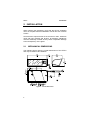
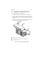
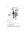
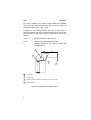
GFC-5
Installation Manual
GFC-5
INSTALLATION MANUAL
Product names mentioned herein are for identification purposes only and may
be trademarks and or registered trademarks of their respective companies.
Datalogic reserves the right to make modifications and improvements without
prior notiification.
© - 1997 Datalogic S.p.A.
821190043 (Rev. D)
CONTENTS
Safety Precautions........................................................... iv
1
INTRODUCTION ..............................................................1
2
2.1
2.2
2.3
2.4
2.5
INSTALLATION ...............................................................2
Mechanical Dimensions....................................................2
Assembly to DS50AF and DS6100...................................3
Assembly to DS45A, LS50 and DS/LS6100 .....................4
Reading Features .............................................................5
Adjustment........................................................................7
3
MAINTENANCE AND TROUBLESHOOTING.................9
4
4.1
TECHNICAL FEATURES...............................................10
Technical Data................................................................10
iii
SAFETY PRECAUTIONS
WARNING
Once the scanner-oscillating
mirror reading system is
assembled, the laser beam is
emitted from the output window
of the GFC-5. All the
precautions regarding laser
exposure must be taken,
(details are given in the
Installation manual of the
scanner).
The following label is applied near the output window of the
GFC-5.
iv
DATALOGIC
1
GFC-5
INTRODUCTION
The GFC-5 oscillating mirror is an accessory for the following
laser scanner series: DS45A, DS50AF, DS6100, LS50 and
LS6100. It is designed to generate homogeneous and
adjustable raster reading through deflection of the scanning
laser beam.
The system consists of the oscillating mirror attached to the
scanner and allows a surface instead of a line to be observed;
versatility and reading accuracy are therefore increased in
"Picket Fence" reading mode.
Some examples are given in the following cases: codes
presented at different "heights" on the reading surface; codes
with printing defects.
The electronic and electromechanical components controlling
the mirror movement are contained inside the rugged metal
casing, which guarantees protection class IP64 when the GFC-5
is mounted correctly on the scanner.
The device operates exclusively at low power, between 10 and
30VDC. GFC-5 is supplied with a bipolar connector for direct
plug-in connection to DS50AF and DS6100 conector model
scanners.
For models DS45A, LS50 and DS/LS6100 (without sockets
dedicated to the GFC-5), the oscillating mirror may be powered
by the same source used for the scanner. Further details are
given in Chapter 2.
1
GFC-5
2
DATALOGIC
INSTALLATION
When opening the packaging, verify that the GFC-5 oscillating
mirror is complete with the installation manual and set of fixture
screws.
Check that the output window of the scanner is clean, otherwise
clean with soft material and alcohol; all abrasive substances
must be absolutely avoided as they cause irrepairable damage
to the transparency of the glass.
2.1
MECHANICAL DIMENSIONS
The following figure gives the overall dimensions of the GFC-5
and may be used for its installation.
Figure 1 - Overall dimensions
2
DATALOGIC
2.2
GFC-5
ASSEMBLY TO DS50AF AND DS6100
For the following procedure see Figure 2.
1)
Remove the protective covering from the oscillating mirror.
2)
Align the GFC-5 over the output window of the scanner and
join the devices using the screws supplied, tighten the
screws.
3)
Insert and lock the bipolar connector of the oscillating mirror
in the power socket provided on the scanner.
2
1
1
3
1
Fixing screws supplied with GFC-5.
2
Removable screw on cap for access to the raster width adjustment.
3
Power socket for the GFC-5.
Figure 2 - GFC-5 assembly to DS50AF and DS6100
3
GFC-5
DATALOGIC
1
2
1 = Positive voltage
2 = GND
Figure 3 - External view of the bipolar connector (pin side)
2.3
ASSEMBLY
DS/LS6100
TO
DS45A,
LS50
AND
For the following procedure see Figure 4.
1)
Remove the protective covering from the oscillating mirror.
2)
Align the GFC-5 over the output window of the scanner and
join the devices using the two screws supplied, tighten the
screws. These scanner models do not have a power socket
for the oscillating mirror; the electrical power necessary to
operate the device is between 10 and 30 VDC and can be
supplied from the same source used for the scanner, using
a 2 wire flexible cable to replace the standard.
3)
Remove the cover of the oscillating mirror with care,
unscrew the terminal block connecting the power supply
cable to the printed circuit (Yellow = Positive, Input voltage;
Green = Negative, ground) and remove existing cable after
loosening the cable gland.
4)
Connect the new power cable, respecting the voltage
polarity given on the terminals and on the printed circuit.
The new power cable must have the following features:
Maximum external diameter:
Minimum section of each conductor:
4
= 5 mm
2
= 0.25 mm
DATALOGIC
GFC-5
3
1
2
original cable
yellow (pos.)
green (neg.)
4
1
Removable screw on cap for access to the raster width setting.
2
GFC-5 fixture screws.
3
Fixing screws for the GFC-5 cover.
4
Power cable connection terminal block.
Figure 4 - GFC-5 assembly to DS45A, LS50, and DS/LS6100
2.4
READING FEATURES
The oscillating mirror mounted on the scanner reduces the
reading distance indicated in the features and reading diagrams
given in the Installation manual of the scanner (which contains
relative details).
5
GFC-5
DATALOGIC
The path covered by the optical signal inside the oscillating
mirror must be subtracted from this data; as seen in Figure 5,
this path results to be A + B = 74 mm.
Furthermore, the reading features decrease by about 10% in
typical conditions due to the optical signal passing through the
output window of the GFC-5 and the reflection on the mirror
surface.
A+B+C
= Reading distance of the scanner
A+B
= Optical signal path inside the GFC-5
C
= Reading distance of the scanner system with
oscillating mirror.
4
3
2
1
1
Code surface.
2
Output window.
3
Reference surface to measure the reading distance of the scanner.
4
Oscillating mirror.
Figure 5 - Calculating GFC-5 reading distance
6
DATALOGIC
2.5
GFC-5
ADJUSTMENT
The scanner-oscillating mirror reading system can operate in all
positions.
For alignment, the output window of the oscillating mirror is
considered equivalent to that of a scanner when the raster width
is equal to 0° .
The raster width of the GFC-5 is factory set at 20°; however, this
value is adjustable to suit individual reading requirements: turn
the trimmer indicated in Figure 6 in a clockwise direction to
obtain a variable width from 0° to 30°. Note that by limiting the
raster width to the minimum necessary, the number of scans on
the reading surface is increased.
The oscillation frequency of the GFC-5 mirror is factory set to 10
Hz. This frequency is variable upon request from 5 to 30 Hz to
satisfy specific requirements; this adjustment procedure must
be performed by qualified Datalogic personnel.
7
GFC-5
DATALOGIC
4
3
h = 27 mm
1
2
1
Reading surface for raster width ≠ 0°.
2
Reading line for raster width = 0°.
3
Access to the raster width adjustment trimmer.
4
Supporting surface height of the oscillating mirror and of the plane created by the
laser beam during its scanning for raster width = 0°.
Figure 6 - GFC-5 adjustment
8
DATALOGIC
3
GFC-5
MAINTENANCE AND
TROUBLESHOOTING
GFC-5 has no user replaceable components and, apart from
periodically cleaning the output window, no particular
maintenance is necessary; dust and dirt on the surface may
alter the reading performance of the system. Clean the window
with soft material and alcohol, absolutely avoiding all abrasive
substances.
If the device does not operate correctly, verify the power supply
is present and the raster width setting is correct.
WARNING
Do not remain in the laser
beam output zone during these
procedures.
Integrate the operating controls of the scanner with the above.
Please consult your nearest Datalogic distributor if the problem
persists after all the tests.
9
GFC-5
4
DATALOGIC
TECHNICAL FEATURES
4.1
TECHNICAL DATA
ELECTRICAL CHARACTERISTICS (see NOTE )
Max. Input voltage
35 Vdc
Operating voltage (see CAUTION)
10 to 30 Vdc
Input current
250 mA max
Internal fuse
500 mA slow blow
Raster width
user adjustable from 0° to 30°
(for further details see paragraph 2.5)
Oscillation frequency
10 Hz (for further details see
paragraph 2.5)
READING FEATURES
See paragraph 2.4 and the scanner Installation manual
ENVIRONMENTAL FEATURES
Operating temperature
-5 °C/+45 °C (23 °F/113 °F)
Storage temperature
-20 °C/+70 °C (-4 °F to 158 °F)
Max. relative humidity
90% non condensing
Vibration Resistance
IEC 68-2-6 Test FC
1.5 mm; 10: 55 Hz; 2 hours
x, y, z axis
Shock resistance
IEC 68-2-27 Test EA
30 G; 11 ms; 3 shocks
x, y, z axis
Protection class
IP64 (when correctly mounted on the
scanner)
PHYSICAL FEATURES
Mechanical dimensions
182 x 97 x 61 mm
(7.1 x 3.8 x 2.4 in)
Weight
10
approximately 850 g (30 oz)
DATALOGIC
GFC-5
NOTE
The features indicated are to
be considered typical at an
ambient temperature of 25 °C
(77 °F), if not specified
differently.
CAUTION
Input voltage less than 10 V will
blow the fuse.
11