1
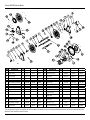
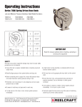
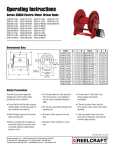
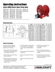
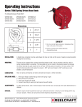
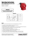
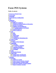
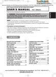
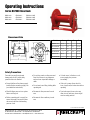
Operating Instructions
Series B37000 Hose Reels
BB37118 L
BB37122 L
BB37128 L
CB37118 L
CB37122 L
CB37128 L
EB37118 L12D
EB37122 L12D
EB37128 L12D
Dimensional Data
A
B
Part #
D
A
B
C
D
BB/CB37118 L
31 3/4”
18”
-----
21 3/4”
EB37118 L12D
-----
18”
31”
21 3/4”
BB/CB37122 L
35 3/4”
22”
-----
25 3/4”
EB37122 L12D
-----
22”
35”
25 3/4”
BB/CB37128 L
40 3/4”
27”
-----
30 3/4”
EB37128 L12D
-----
27”
40”
30 3/4”
C
Safety Precautions
Personal injury and/or equipment
damage may result if proper safety
precautions are not observed.
• Do not play pranks on other personnel.
Even low pressure is very dangerous
and can cause irrepairable damage or
death.
• Ensure that the reel has been properly
installed before connecting supply line
(see installation instructions).
• Do not wear loose fitting clothing while
operating reel.
• Bleed fluid/gas pressure from system
before servicing reel.
• Be aware of other personnel in work
area.
• Before connecting reel to supply line
ensure that supply line pressure does
not exceed maximum rated working
pressure of reel.
• Be aware of other machinery in work
area.
• If a leak occurs in the hose or reel,
remove supply line pressure
immediately.
• If the reel is power driven check for
loose, frayed, and/or broken wires before
operating.
• Treat and respect a hose reel as any
other piece of machinery, observing all
common safety practices.
Form# 1255-1030 Rev: 8/2014
Reelcraft Industries, Inc. • 2842 E Business Hwy 30, Columbia City, IN 46725
Ph: 800-444-3134 / 260-248-8188 • Fax: 800-444-4587 / 260-248-2605
Customer Service: 855-634-9109 • [email protected] • www.reelcraft.com
Series B37000 Hose Reels
INSTALLATION INSTRUCTIONS
Inspection
Unpack and inspect the reel for damage.
Turn the reel by hand to check for smooth
operation. Check for completeness.
Mounting of all hose reels
NOTE: Ensure that mounting surface is
flat to prevent binding on reel after it is
mounted.
1. Two 1/2” diameter mounting holes are
located at the base of each side
support panel (2 each). Mount reel
using four (customer supplied) bolts;
tightening them securely to ensure a
solid, rigid attachment.
Manual Driven Reels
Additional mounting instructions are not
required.
Power Drive Reels
CAUTION: Remove all electrical power
when wiring. Do not “hot-wire”. Observe
all applicable NEC/OSHA requirements.
1. Ensure that supply and motor voltage
ratings are compatible.
2. Consult wiring diagrams and determine
which one is applicable to your reel.
3. Perform electrical wiring following
applicable diagram.
DOUBLE POLE SINGLE-THROW SWITCH
110 Volt A.C.
OPERATING INSTRUCTIONS
Hot
Neutral
2. Perform the following steps only after
all other installation steps, pertaining
to your particular reel, are
accomplished. Refer to page 4 for
special instructions.
NOTE: A flexible hose connection must be
used to compensate for any offset between
the supply line and the reel swivel.
3. Apply thread compound to all threads.
4. Thread male connector of supply line
into swivel. Tighten securely.
3. Using a wrench, firmly hold onto
connecting tube assembly while
tightening hose connector.
SINGLE POLE SINGLE-THROW
Connection shown
gives counterclockwise rotation
looking at end of
motor shaft. To
reverse rotation
interchange Leads
5, 6.
12/24 VOLT D.C.
Connecting the hose
CAUTION: Do not connect the hose to the
connecting tube assembly until after hose
reel has been installed. Fully extend and
charge hose before winding on ot reel.
Momentarily open control valve, when
initially charging, to purge hose of gases.
When fluid appears at control valve, close
valve. This prevents flattening of the hose
and excessive pressure on the drum when
fluid supply is reinitialized at a later time.
WARNING-PREVENT STATIC
SPARKING: When working around flammable liquids such as solvents, paints,
chemicals or petroleum products, ensure
that the hose reel, hose and the equipment
being serviced are properly grounded.
Use grounded hose(s) (static wire). Use
an ohmmeter to check continuity of the
ground circuit. Fire and/or explosion can
result if proper grounding is not achieved.
If reel is power or air driven, be careful of
chain/sprocket drive system. Keep hands
clear. Do not wear loose fitting clothing. Pull hose from the reel by grasping
the hose itself, not the control handle or
swivel.
SERVICE INSTRUCTIONS
Replacing the hose
1. Using a wrench, firmly hold onto the
connecting tube assembly while
removing hose connector.
2. Follow procedures for “Connecting the
hose” (refer to installation
instructions).
1. Apply thread compound to all threads.
2. Hand thread male hose connector into
connecting tube assembly.
Page 2
www.reelcraft.com
Series B37000 Hose Reels
Replacing the swivel
CAUTION: Remove supply line pressure
before performing the following procedure.
1. Remove supply line from swivel.
2. Remove swivel assembly from inlet
shaft.
3. Install swivel assembly to inlet shaft by
reversing steps 1 and 2. Apply thread
compound to all threads.
Replacing the motor
CAUTION: Before replacing the motor,
remove all electrical power or air pressure
from motor.
1. Disconnect wiring/air lines from motor.
2. Remove bolts securing motor mounting
bracket to reel. Remove bracket (refer
to diagram on page 3).
3. Install swivel assembly to inlet shaft by
reversing steps 1 and 2. Apply thread
compound to all threads.
(3) places
(4) places
ADJUSTMENT PROCEDURES
Adjusting the reel
1. Adjust reel drag by loosening or
tightening set screw on hub casting on
manual driven reel.
Adjusting the chain tension
CAUTION: Before adjusting the chain
tension, remove all electrical power or
air pressure from motor. Over-tensioned
(tightening) of chain results in reduced
motor life. Adjust to allow between 1/4 and
1/2 inch play in chain.
1. Loosen bolts (do not remove) securing
motor mounting bracket to reel.
2. Move motor mounting bracket and
motor until proper chain tension is
obtained.
3. Tighten motor mounting bracket bolts.
Replacing the chain
CAUTION: Before replacing the chain,
remove all electrical power or air pressure
from motor.
1. Loosen (do not remove) bolts securing
motor mounting bracket in place.
2. Remove chain master-link.
3. Remove chain master-link. Install new
chain by reversing steps 1 and 2
above.
www.reelcraft.com
Page 3
Series B37000 Hose Reels
ITEM
DESCRIPTION
1 Swivel (1" x 1") Aflas
Cap Screw
2 Hex
(5-16-18 x 2)
Tapping Screw
3 Self
(5/6-12 x 5/8)
4 Snap Ring (1 1/4 ID)
5 Side Frame
QTY. BB37118 L BB37122 L BB37128 L ITEM
DESCRIPTION
1
600682
600682
600682
19 Lock Nut (5/16-18)
20
Nyloc Nut (1/4-20)
QTY.
8
BB37118 L
BB37122 L
BB37128 L
300107
300107
300107
1
300070
300070
300070
261501-3
261501-4
261501-5
8
S2-51
S2-51
S2-51
12
S317-31
S317-31
S317-31
21
Cross Brace
2
3
2
300007
260403
300007
260403
300007
260403
22
23
6
1
602588
602588
602588
24
6
Hub & Bearing Assembly
2
7
8
9
10
Inlet Shaft
Spool Flange
Set Screw (3/8-16 x 1/2)
Tie Rod
1
2
2
4
11
Spool Spacer
1
261775-3
261775-4
261775-5
29
12
U-Botl (1")
1
261395
261395
261395
30
13
Hub & Bearing Assembly
2
600640
600640
600640
30
14
Nyloc Nut (5/16-18)
8
S85-7
S85-7
S85-7
31
15
Lock Handle Assembly
1
280109
280109
280109
32
Flange Nut (10-32)
Bevel Gear
Flat Cap Screw
(10-32 x 5/8)
Lock Nut (5/16-18)
Crank & Handle Assembly
Lock Washer
Hex Nut
Hex Cap Screw
(5-16-18 x 5/8)
Crank Support
(Right Side)
Crank Support (Left Side)
Hand Rewind Assembly
(Offset Left)
Hex Flange Screw
(3/8-16 x 1-1/4)
18
Support Shaft
1
260770
260770
260770
---
Reinforcement Spring*
262658
262658
262658
260399-3 260399-3 260399-3
300006
300006
300006
260402-300 260402-400 260402-500
25
26
27
28
6
2
1
2
2
S79-3
S79-3
S79-3
323058M-ANZ 323058M-ANZ 323058M-ANZ
S27-108
S27-108
S27-108
300107
300107
300107
390838-10-35 390838-10-35 390838-10-35
S339-616
S339-616
S339-616
S77-6
S77-6
S77-6
2
S2-52
S2-52
S2-52
1
262344
262344
262344
1
262344L
262344L
262344L
1
391843-1-ANZ 391843-1-ANZ 391843-1-ANZ
2
S44-6
S44-6
S44-6
1
261683
261683
261683
*The reinforcement spring is inserted into the hose where it connects to the reel ensuring that the hose does not pinch or become restricted
where the hose transitions onto the spool.
Page 4
www.reelcraft.com
Series B37000 Hose Reels
ITEM
QTY.
CB37118 L
CB37122 L
CB37128 L
1
Swivel (1" x 1") Aflas
DESCRIPTION
1
600682
600682
600682
600682
600682
600682
2
Hex Cap Screw (5-16-18 x 2)
8
S2-51
S2-51
S2-51
S2-51
S2-51
S2-51
3
Self Tapping Screw (5/6-12 x 5/8)
12
S317-31
S317-31
S317-31
S317-31
S317-31
S317-31
4
Snap Ring (1 1/4 ID)
3
300007
300007
300007
300007
300007
300007
EB37118 L12D EB37122 L12D EB37128 L12D
5
Side Frame
2
260403
260403
260403
260403
260403
260403
6
Hub & Bearing Assembly
2
602588
602588
602588
602588
602588
602588
7
Inlet Shaft
1
262658
262658
262658
262658
262658
262658
8
Spool Flange
2
260399-3
260399-3
260399-3
260399-3
260399-3
260399-3
9
Set Screw (3/8-16 x 1/2)
2
300006
300006
300006
300006
300006
300006
10
Tie Rod
4
260402-300
260402-400
260402-500
260402-300
260402-400
260402-500
11
Spool Spacer
1
261775-3
261775-4
261775-5
261775-3
261775-4
261775-5
12
U-Botl (1")
1
261395
261395
261395
261395
261395
261395
13
Hub & Bearing Assembly
2
600640
600640
600640
600640
600640
600640
14
Nyloc Nut (5/16-18)
8
S85-7
S85-7
S85-7
S85-7
S85-7
S85-7
15
Lock Handle Assembly
1
280109
280109
280109
280109
280109
280109
16
Set Screw (3/8-16 x 3/8)
1
300089
300089
300089
------
------
------
17
Crank Handle Assembly
1
600102
600102
600102
------
------
------
18
Support Shaft
1
260770
260770
260770
260770
260770
260770
19
Lock Nut (5/16-18)
8
300107
300107
300107
300107
300107
300107
20
Nyloc Nut (1/4-20)
1
300070
300070
300070
300070
300070
300070
21
Cross Brace
2
261501-3
261501-4
261501-5
261501-3
261501-4
261501-5
33
Motor
1
------
------
------
260409
260409
260409
34
Motor Gear
1
------
------
------
260408
260408
260408
35
Hex Cap Screw (5-16-18 x 5/8)
4
------
------
------
S2-52
S2-52
S2-52
36
Motor Bracket
1
------
------
------
260405
260405
260405
37
Flat Washer (5/16 ID)
4
------
------
------
300039
300039
300039
38
Hex Cap Screw (5-16-18 x 5/8)
4
------
------
------
S2-52
S2-52
S2-52
39
Flange Nut (10-32)
6
------
------
------
S79-3
S79-3
S79-3
40
Spool Gear (112T)
1
------
------
------
260407
260407
260407
41
Gear Spacer
6
------
------
------
260410
260410
260410
42
Flat Cap Screw (10-32 x 1-1/8)
6
------
------
------
S27-112
S27-112
S27-112
43
Drive Chain
1
------
------
------
260406
260406
260406
44
Nyloc Nut (5/16-18)
4
------
------
------
S85-7
S85-7
S85-7
---
Reinforcement Spring*
1
261683
261683
261683
261683
261683
261683
*The reinforcement spring is inserted into the hose where it connects to the reel ensuring that the hose does not pinch or
become restricted where the hose transitions onto the spool.
www.reelcraft.com
Page 5