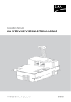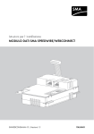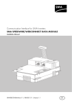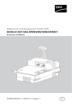
1
Installation Manual
SMA SPEEDWIRE/WEBCONNECT DATA MODULE
A
B
1
x
.BG
xxxx xx -10
FA:SER:PWDM
S
SWWEBCONDM-IA-en-16 | Version 1.6
ENGLISH
Legal Provisions
SMA Solar Technology AG
Legal Provisions
The information contained in this document is the property of SMA Solar Technology AG. Publishing
its content, either partially or in full, requires the written permission of SMA Solar Technology AG.
Any internal company copying of the document for the purposes of evaluating the product or its
correct implementation is allowed and does not require permission.
SMA Warranty
You can download the current warranty conditions from the Internet at www.SMA-Solar.com.
Trademarks
All trademarks are recognized, even if not explicitly identified as such. A lack of identification does
not mean that a product or symbol is not trademarked.
The BLUETOOTH® word mark and logos are registered trademarks owned by Bluetooth SIG, Inc.
and any use of these marks by SMA Solar Technology AG is under license.
Modbus® is a registered trademark of Schneider Electric and is licensed by the Modbus
Organization, Inc.
QR Code is a registered trademark of DENSO WAVE INCORPORATED.
Phillips® and Pozidriv® are registered trademarks of Phillips Screw Company.
Torx® is a registered trademark of Acument Global Technologies, Inc.
SMA Solar Technology AG
Sonnenallee 1
34266 Niestetal
Germany
Tel. +49 561 9522-0
Fax +49 561 9522-100
www.SMA.de
E-mail: [email protected]
© 2004 to 2014 SMA Solar Technology AG. All rights reserved.
2
SWWEBCONDM-IA-en-16
Installation Manual
SMA Solar Technology AG
Table of Contents
Table of Contents
1 Information on this Document. . . . . . . . . . . . . . . . . . . . . . . . . . . 5
1.1
1.2
1.3
1.4
1.5
1.6
1.7
Validity. . . . . . . . . . . . . . . . . . . . . . . . . . . . . . . . . . . . . . . . . . . . . . . . .
Target Group . . . . . . . . . . . . . . . . . . . . . . . . . . . . . . . . . . . . . . . . . . . .
Additional Information . . . . . . . . . . . . . . . . . . . . . . . . . . . . . . . . . . . . .
Symbols . . . . . . . . . . . . . . . . . . . . . . . . . . . . . . . . . . . . . . . . . . . . . . . .
Typographies. . . . . . . . . . . . . . . . . . . . . . . . . . . . . . . . . . . . . . . . . . . .
Nomenclature . . . . . . . . . . . . . . . . . . . . . . . . . . . . . . . . . . . . . . . . . . .
Figures . . . . . . . . . . . . . . . . . . . . . . . . . . . . . . . . . . . . . . . . . . . . . . . . .
5
5
5
6
6
7
7
2 Safety . . . . . . . . . . . . . . . . . . . . . . . . . . . . . . . . . . . . . . . . . . . . . . 8
2.1
2.2
2.3
2.4
Intended Use . . . . . . . . . . . . . . . . . . . . . . . . . . . . . . . . . . . . . . . . . . . . 8
Safety Precautions . . . . . . . . . . . . . . . . . . . . . . . . . . . . . . . . . . . . . . . . 8
Operating Instructions . . . . . . . . . . . . . . . . . . . . . . . . . . . . . . . . . . . . . 9
Supported Products . . . . . . . . . . . . . . . . . . . . . . . . . . . . . . . . . . . . . . 10
3 Scope of Delivery . . . . . . . . . . . . . . . . . . . . . . . . . . . . . . . . . . . . 11
4 Product Description . . . . . . . . . . . . . . . . . . . . . . . . . . . . . . . . . . 12
4.1
4.2
4.3
4.4
Speedwire/Webconnect Data Module . . . . . . . . . . . . . . . . . . . . . .
Possible Network Topologies . . . . . . . . . . . . . . . . . . . . . . . . . . . . . .
Type Label . . . . . . . . . . . . . . . . . . . . . . . . . . . . . . . . . . . . . . . . . . . . .
Cable Gland . . . . . . . . . . . . . . . . . . . . . . . . . . . . . . . . . . . . . . . . . . .
12
13
13
14
5 Connection . . . . . . . . . . . . . . . . . . . . . . . . . . . . . . . . . . . . . . . . . 15
5.1
5.2
5.3
5.4
Mounting Position and Cable Route . . . . . . . . . . . . . . . . . . . . . . . . .
Cable Requirements and Information on Cable Routing . . . . . . . . . .
Installing the Speedwire/Webconnect Data Module . . . . . . . . . . . .
Connecting the Speedwire/Webconnect Data Module . . . . . . . . . .
Installation Manual
SWWEBCONDM-IA-en-16
15
15
16
18
3
Table of Contents
SMA Solar Technology AG
6 Commissioning . . . . . . . . . . . . . . . . . . . . . . . . . . . . . . . . . . . . . . 20
6.1 Commissioning a Large-Scale PV Power Plant with
Cluster Controller. . . . . . . . . . . . . . . . . . . . . . . . . . . . . . . . . . . . . . . . 20
6.2 Commissioning a Small-Scale PV System. . . . . . . . . . . . . . . . . . . . . . 20
6.3 Managing a Small-Scale PV System with Sunny Explorer . . . . . . . . . 21
6.3.1 Functions and Parameter Settings in Sunny Explorer . . . . . . . . . . . . 21
6.3.2 Creating a Small-Scale PV System in Sunny Explorer . . . . . . . . . . . 22
6.4 Configuring the Modbus Function . . . . . . . . . . . . . . . . . . . . . . . . . . . 22
6.5 System Registration in Sunny Portal . . . . . . . . . . . . . . . . . . . . . . . . . . 23
6.5.1 Registering a Large-Scale PV Power Plant with Cluster Controller
in Sunny Portal . . . . . . . . . . . . . . . . . . . . . . . . . . . . . . . . . . . . . . . . . 23
6.5.2 Registering the Small-Scale PV System in Sunny Portal . . . . . . . . . . 23
7 Decommissioning . . . . . . . . . . . . . . . . . . . . . . . . . . . . . . . . . . . . 25
7.1 Removing the Speedwire/Webconnect Data Module . . . . . . . . . . . 25
7.2 Packaging the Speedwire/Webconnect Data Module for
Shipping . . . . . . . . . . . . . . . . . . . . . . . . . . . . . . . . . . . . . . . . . . . . . . 25
7.3 Disposing of the Speedwire/Webconnect Data Module . . . . . . . . . 25
8 Troubleshooting . . . . . . . . . . . . . . . . . . . . . . . . . . . . . . . . . . . . . 26
9 Technical Data . . . . . . . . . . . . . . . . . . . . . . . . . . . . . . . . . . . . . . 28
10 Contact . . . . . . . . . . . . . . . . . . . . . . . . . . . . . . . . . . . . . . . . . . . . 29
4
SWWEBCONDM-IA-en-16
Installation Manual
SMA Solar Technology AG
1 Information on this Document
1 Information on this Document
1.1 Validity
This document is valid for device type "SWDM-10.GR1" (Speedwire/Webconnect data module)
from hardware version A and firmware version 1.00.20.R.
1.2 Target Group
The tasks described in this document must be performed by qualified persons only. Qualified persons
must have the following skills:
• Training in the installation and commissioning of electrical devices and installations
• Knowledge of how to deal with the dangers and risks associated with installing and using
electrical devices and installations
• Knowledge of all applicable standards and directives
• Knowledge of how an inverter works and is operated
• Knowledge of and compliance with this document and all safety precautions
1.3 Additional Information
Links to additional information can be found at www.SMA-Solar.com. Not all documents are
available in all languages.
Document title
Document type
Firmware Update with SD Card
Technical Description
SMA Speedwire Fieldbus
Technical Information
SMA Modbus® Interface
Technical Description
®
SunSpec
Modbus®
Installation Manual
Interface
Technical Description
SWWEBCONDM-IA-en-16
5
1 Information on this Document
SMA Solar Technology AG
1.4 Symbols
Symbol
Explanation
Indicates a hazardous situation which, if not avoided, will result in death
or serious injury
Indicates a hazardous situation which, if not avoided, can result in death
or serious injury
Indicates a hazardous situation which, if not avoided, can result in minor
or moderate injury
Indicates a situation which, if not avoided, can result in property damage
Information that is important for a specific topic or goal, but is not
safety-relevant
☐
Indicates a requirement for meeting a specific goal
☑
Desired result
✖
A problem that might occur
1.5 Typographies
Typography
bold
Explanation
• Display texts
• Elements on a user interface
>
[Button/Key]
6
Example
• The value can be found in the
field Energy.
• Terminals
• Select Settings.
• Elements to be selected
• Enter the value 10 in the field
Minutes.
• Elements to be entered
• Connects several elements to
be selected
• Button or key to be selected or
pressed
SWWEBCONDM-IA-en-16
• Select Settings > Date.
• Select [Next].
Installation Manual
SMA Solar Technology AG
1 Information on this Document
1.6 Nomenclature
Complete designation
Designation in this document
Photovoltaic system
PV system
Small-scale photovoltaic system
Small-scale PV system
Large-scale photovoltaic power plant
Large-scale PV power plant
SMA Cluster Controller
Cluster Controller
SMA Speedwire
Speedwire
SMA Speedwire/Webconnect Data Module
Speedwire/Webconnect Data Module
SMA Webconnect function
Webconnect function
SMA inverter
Inverter
1.7 Figures
The figures in this document have been created for Sunny Boy inverters and may deviate slightly in
some cases for Sunny Tripower inverters.
Installation Manual
SWWEBCONDM-IA-en-16
7
2 Safety
SMA Solar Technology AG
2 Safety
2.1 Intended Use
The Speedwire/Webconnect data module is a Speedwire communication interface with
Webconnect function for inverters.
Speedwire is a cable-based type of communication based on the Ethernet standard and the
communication protocol SMA Data2+. This enables inverter-optimized 10/100 Mbit data
transmission between Speedwire devices in PV systems. The Webconnect function enables direct data
transmission between the inverters of a small-scale PV system and the Internet portal Sunny Portal
without any additional communication device and for a maximum of four inverters per Sunny Portal
system. For this, a Speedwire/Webconnect data module must be installed in each of the inverters.
You can access your Sunny Portal system from any computer with an Internet connection.
The inverter still complies with the standard after the product has been installed.
For safety reasons, it is not permitted to modify the product or install components that are not explicitly
recommended or distributed by SMA Solar Technology AG for this product.
The type label must remain permanently attached to the product.
Use the Speedwire/Webconnect data module only in accordance with the enclosed documentation
and with the local standards and directives. Any other application may cause personal injury or
property damage.
The enclosed documentation is an integral part of this product.
• Read and observe the documentation.
• Keep the documentation in a convenient place for future reference.
2.2 Safety Precautions
This section contains safety precautions that must be observed at all times when working on or with
the product. To prevent personal injury and property damage and to ensure long-term operation of
the product, read this section carefully and follow all safety precautions at all times.
Danger to life due to electric shock when opening the inverter
High voltages are present in the conductive components of the inverter. Touching live components
results in death or serious injury.
• Prior to performing any work on the inverter, always disconnect the inverter from all voltage
sources on the AC and DC sides (see inverter installation manual). Observe the waiting time
to allow the capacitors to discharge.
8
SWWEBCONDM-IA-en-16
Installation Manual
SMA Solar Technology AG
2 Safety
Risk of burns due to hot enclosure parts
Some parts of the inverter enclosure can get hot during operation. Touching these enclosure parts
can result in burn injuries.
• Do not touch any parts other than the lower enclosure lid of the inverter during operation.
Damage to the inverter due to electrostatic discharge
The internal components of the inverter can be irreparably damaged by electrostatic discharge.
• Ground yourself before touching any inverter component.
2.3 Operating Instructions
High costs possible due to inappropriate Internet tariffs
When using the Webconnect function, a constant Internet connection is required.
Depending on the quality of the Internet connection, the data transfer volume for an inverter is
between 150 MB and 550 MB per month. When using the system overview in Sunny Portal with
live data display, there is an additional data volume of 600 kB per hour.
• Since there is a permanent Internet connection to Sunny Portal, time-based billing systems
should be avoided. High costs could be incurred. SMA Solar Technology AG recommends
using an Internet flat rate.
If UMTS is used, VoIP is required
If UMTS is used, VoIP (Voice over IP) is required to use the Webconnect function.
• Ensure that the UMTS provider also provides the VoIP service.
Installation Manual
SWWEBCONDM-IA-en-16
9
2 Safety
SMA Solar Technology AG
2.4 Supported Products
SMA inverter
The Speedwire/Webconnect data module must only be installed in the following SMA inverters from
the indicated inverter firmware version:
SMA Inverter*
From inverter firmware version
SB 2500TLST-21
2.53**
SB 3000TLST-21
SB 3000TL-21
SB 3600TL-21
SB 4000TL-21
SB 5000TL-21
SB 6000TL-21
STP 8000TL-10
STP 10000TL-10
STP 12000TL-10
STP 15000TL-10
STP 17000TL-10
STP 15000TLEE-10
STP 15000TLHE-10
STP 20000TL-30
all
STP 25000TL-30
STP 20000TLEE-10
2.53**
STP 20000TLHE-10
* For information on which of these SMA inverters with Speedwire/Webconnect data module supports the Modbus interface
of the Speedwire/Webconnect data module, see the datasheet "SMA_Modbus-DB-en.xlsx" at www.SMA-Solar.com.
** If the firmware version of the inverter is lower than 2.53, you must perform a firmware update to version 2.53 or higher for
this inverter. For information on performing the firmware update, refer to the Technical Description "Firmware Update with
SD Card" at www.SMA-Solar.com.
Additional SMA Products
The Speedwire/Webconnect data module can be configured with the following communication
products:
• SMA Cluster Controller from firmware version 1.0
• Sunny Explorer from software version 1.06
• SMA Connection Assist from software version 1.00.8.R
Sunny Explorer and SMA Connection Assist are available free of charge at www.SMA-Solar.com.
10
SWWEBCONDM-IA-en-16
Installation Manual
SMA Solar Technology AG
3 Scope of Delivery
3 Scope of Delivery
Check the delivery for completeness and any visible external damage. Contact your distributor if the
scope of delivery is incomplete or if there is any damage.
Order option: Speedwire/Webconnect data module pre-installed in the inverter
Figure 1:
Components of the order option "Speedwire/Webconnect data module pre-installed in the inverter"
Position
Quantity
Designation
A
1
Installation manual
B
1
M32 cable gland with sealing plug, two-hole cable support sleeve and
counter nut
C
1
Label with PIC (Product Identification Code, identification key for
registration in Sunny Portal) and RID (Registration Identifier, registration ID
in Sunny Portal)
Order Option: Speedwire/Webconnect data module as retrofit kit
A
B
D
n
tio
ra
ist xxx
eg xx
l R xx
r t a xx
Po xx
y xx X
nn xx X X
S u C : XX x
PI D :
RI
Figure 2:
C
X
XX
XX
XX XX
XX X XX
XX XX XX
XX XX XX
XX XX XX
XX XX XX
XX XX XX
XX XX XX
XX XX
XX
A
B
Components of the order option "Speedwire/Webconnect data module as retrofit kit"
Position
Quantity
Designation
A
1
Speedwire/Webconnect data module (SWDM-10)
B
1
Installation manual
C
1
M32 cable gland with sealing plug, two-hole cable support sleeve and
counter nut
D
2
Label with PIC and RID for registration of a small-scale PV system in
Sunny Portal
Installation Manual
SWWEBCONDM-IA-en-16
11
4 Product Description
SMA Solar Technology AG
4 Product Description
4.1 Speedwire/Webconnect Data Module
The Speedwire/Webconnect data module is a Speedwire communication interface with Webconnect
function for inverters.
Speedwire is a cable-based type of communication based on the Ethernet standard and the
communication protocol SMA Data2+. This enables inverter-optimized 10/100 Mbit data
transmission between Speedwire devices in PV systems. The Webconnect function enables direct data
transmission between the inverters of a small-scale PV system and the Internet portal Sunny Portal
without any additional communication device and for a maximum of four inverters per Sunny Portal
system. For this, a Speedwire/Webconnect data module must be installed in each of the inverters.
You can access your Sunny Portal system from any computer with an Internet connection.
The Speedwire/Webconnect data module performs the following tasks:
• Set-up of a Speedwire network in small-scale and large-scale PV power plants
• Data exchange with Sunny Portal:
– In small-scale PV systems via a router with Internet connection
– In large-scale PV power plants via the Cluster Controller
• Data exchange with Sunny Explorer from version 1.06
• For PV systems in Italy: Connection to or disconnection from the utility grid and definition of the
frequency limits to be used with IEC61850-GOOSE messages
• The Modbus interface* of the Speedwire/Webconnect data module is designed for industrial
use and has the following tasks:
– Remote query of measured values
– Remote setting of parameters
– Setpoint specifications for system control
The Speedwire/Webconnect data module is available as a retrofit kit or is pre-installed in the inverter.
Figure 3:
Design of the Speedwire/Webconnect data module
* For information on which of the supported SMA inverters (see Section 2.4) support the Modbus interface of the Speedwire/
Webconnect data module, see the datasheet "SMA_Modbus-DB-en.xlsx" at www.SMA-Solar.com.
12
SWWEBCONDM-IA-en-16
Installation Manual
SMA Solar Technology AG
Position
Designation
A
Hexagon socket screw (AF 3)
B
Network port A
C
Network port B
D
Ribbon cable plug
E
Ribbon cable
F
Type label
4 Product Description
Label with PIC and RID for registration of a small-scale PV system in Sunny Portal
To activate the Speedwire/Webconnect data module of a small-scale PV system in Sunny Portal, you
will need the PIC and RID numbers printed on the label included in the delivery. After installation of
the Speedwire/Webconnect data module, a label should be attached to the exterior of the inverter
in the vicinity of the type label. Keep the other label in a safe place for future reference.
4.2 Possible Network Topologies
The possible network topologies depend on the devices used and on the number of network ports.
The Speedwire/Webconnect data module has two network ports. For further information on network
topologies, refer to the Technical Information "SMA Speedwire Fieldbus" at www.SMA-Solar.com.
4.3 Type Label
The type label clearly identifies the product. The type label is located in the right-hand top corner on
the front of the product. You can read the following data from the type label:
• Device type (Type)
• Serial number (Serial No.)
• Hardware version (Version)
• PIC
• RID
• MAC address (MAC Address)
You will require the information on the type label to use the product safely and when seeking customer
support from the SMA Service Line.
Installation Manual
SWWEBCONDM-IA-en-16
13
4 Product Description
SMA Solar Technology AG
Symbols on the Type Label
Symbol
Designation
Explanation
CE marking
The product complies with the requirements of the applicable
EU directives.
C-Tick
The product complies with the requirements of the applicable
Australian EMC standards.
Data matrix code
2D code for device-specific characteristics
4.4 Cable Gland
The cable gland fixes the network cables to the inverter enclosure. The cable gland also protects the
interior of the inverter from dust intrusion and moisture penetration.
Figure 4:
Design of cable gland
Position
Designation
A
Filler plug
B
Seal
C
Swivel nut
D
Counter nut
14
SWWEBCONDM-IA-en-16
Installation Manual
SMA Solar Technology AG
5 Connection
5 Connection
5.1 Mounting Position and Cable Route
Figure 5:
Mounting position and cable route in the inverter with the lower enclosure lid open and the display
flipped up
Position
Designation
A
Flipped up display
B
Cable route to the network ports
C
Opening in the inverter enclosure with filler plug
D
Mounting position of the Speedwire/Webconnect data module in the inverter
5.2 Cable Requirements and Information on Cable Routing
The cable length and cable quality affect the signal strength in the Speedwire network. Observe the
following cable requirements and the information on cable laying.
Interference in data transmission due to unshielded energy cables
If unshielded power cables are used, they generate an electromagnetic field during operation
which may induce interference in network cables during data transmission.
• When laying network cables, observe the following minimum clearances to unshielded
energy cables:
– For installation without separating strip: at least 200 mm
– For installation with aluminum separating strip: at least 100 mm
– For installation with steel separating strip: at least 50 mm
Installation Manual
SWWEBCONDM-IA-en-16
15
5 Connection
SMA Solar Technology AG
Cable requirements:
☐ UV-resistant for outdoor use
☐ Number of insulated conductor pairs and insulated conductor cross-section:
at least 2 x 2 x 0.22 mm2 or at least 2 x 2 AWG 24
☐ External diameter of the cable: the maximum external diameter of the cable depends on the size
of the cable gland included in the delivery.
☐ Cable category: Cat5, Cat5e, Cat6, Cat6a, Cat7
☐ Cable shield: SF/UTP, S/UTP, SF/FTP, S/FTP
☐ Plug type: RJ45 for Cat5, Cat5e, Cat6, Cat6a
☐ Cable length between two nodes: max. 50 m with patch cable, max. 100 m with installation
cable
SMA Solar Technology AG recommends the following cable types:
• For outdoor use: SMA COMCAB-OUTxxx*
• For indoor use: SMA COMCAB-INxxx*
The cables are available in the lengths xxx = 100 m, 200 m, 500 m, and 1,000 m.
5.3 Installing the Speedwire/Webconnect Data Module
1.
Danger to life due to electric shock when opening the inverter
High voltages are present in the conductive components of the inverter. Touching live
components results in death or serious injury.
• Disconnect the inverter from all voltage sources on the AC and DC sides and open it
(see the inverter installation manual). Observe the waiting time to allow the capacitors to
discharge.
2. Release the screw of the display far enough to
allow the display to be flipped up.
3. Flip up the display until it snaps into place.
4. Push the pre-mounted filler plug out of the second
hole from the left in the inverter enclosure and retain
it for future decommissioning.
16
SWWEBCONDM-IA-en-16
Installation Manual
SMA Solar Technology AG
5 Connection
5. Attach the cable gland to the enclosure opening
using the counter nut.
6. Insert the Speedwire/Webconnect data module
and slide the ribbon cable upwards behind the
display. The key on the top edge of the Speedwire/
Webconnect data module must fit into the hole in
the plastic retainer in the inverter.
2
1
7. Fasten the Speedwire/Webconnect data module
hand-tight using a hexagon socket screw
(AF 3, torque: 1.5 Nm).
8. Flip the display down.
9. Plug the ribbon cable plug onto the center
connector strip.
10. Stick one of the labels with the data for registration in Sunny Portal (PIC and RID) on the outside
of the inverter in the vicinity of the type label.
11. If you do not wish to proceed immediately with the connection of the Speedwire/Webconnect
data module, close the inverter (see inverter installation manual).
Installation Manual
SWWEBCONDM-IA-en-16
17
5 Connection
SMA Solar Technology AG
5.4 Connecting the Speedwire/Webconnect Data Module
Depending on the system topology you require, you must connect either one or two cables to the
Speedwire/Webconnect data module.
Requirement:
☐ The network cables must be pre-assembled in accordance with the system topology and the
cable requirements (see Section 5.2, page 15).
Additionally required material (not included in the scope of delivery):
☐ Network cable (see Section 5.2 "Cable Requirements and Information on Cable Routing",
page 15)
Procedure:
1.
Danger to life due to electric shock when opening the inverter
High voltages are present in the conductive components of the inverter. Touching live
components results in death or serious injury.
• If the inverter has not yet been opened, disconnect the inverter from all voltage sources
on the AC and DC sides and open it (see the inverter installation manual). Observe the
waiting time to allow the capacitors to discharge.
2. Flip the display up until it snaps into place.
3. Unscrew the swivel nut of the cable gland on the
inverter.
4. Press the seal out of the cable gland from the inside.
18
SWWEBCONDM-IA-en-16
Installation Manual
SMA Solar Technology AG
5 Connection
5. Lead the network cables from the outside into the inverter through the loose swivel nut and the
cable gland.
6. For each network cable, remove one of the filler
plugs from the seal and retain for later
decommissioning.
7. Lead the network cables through the swivel nut and
into the seal. Route the network cable plugs into the
inverter to the network ports.
8. Press the seal into the cable gland. Ensure that any unused cable openings are sealed with filler
plugs.
9. Screw the swivel nut of the cable gland on loosely.
10. Insert the network cables into the network ports. This can be done in any order.
11. Fasten the swivel nut on the cable gland hand-tight. This will fix the network cables in place.
12. Flip the display down and fasten the screw of the display hand-tight.
13. Close the inverter (see inverter installation manual).
14. In a small-scale PV system, depending on the system topology, connect at least one inverter
directly to the router using a network cable.
15. In a large-scale PV power plant with Cluster Controller, connect the Cluster Controller to the
Speedwire network in accordance with the required network topology (see installation manual
of the Cluster Controller).
Installation Manual
SWWEBCONDM-IA-en-16
19
6 Commissioning
SMA Solar Technology AG
6 Commissioning
6.1 Commissioning a Large-Scale PV Power Plant with
Cluster Controller
Requirements:
☐ Speedwire/Webconnect data modules must be installed in the inverters (see Section 5.3,
page 16).
☐ Speedwire/Webconnect data modules must be connected (see Section 5.4, page 18).
☐ The Cluster Controller must be connected to the Speedwire network in accordance with the
desired network topology (see installation manual of the Cluster Controller).
Procedure:
1. Commission all inverters (see inverter installation manual).
2. For optimum operation of large-scale PV power plants with Cluster Controller, deactivate the
Webconnect function of the inverters with installed Speedwire/Webconnect data module
(see user manual of the Cluster Controller). In large-scale PV power plants with
Cluster Controller, communication with Sunny Portal takes place via the Cluster Controller itself.
6.2 Commissioning a Small-Scale PV System
Requirements:
☐ Speedwire/Webconnect data modules must be installed in the inverters (see Section 5.3,
page 16).
☐ Speedwire/Webconnect data module must be connected (see Section 5.4, page 18).
☐ There must be a router with Internet connection in the local network of the system.
☐ At least one inverter must be connected to the router.
☐ If the IP addresses in the local network are to be assigned dynamically, DHCP must be activated
in the router (see the router manual). If you do not want to use DHCP or your router does not
support DHCP, use either SMA Connection Assist or Sunny Explorer to integrate the inverters
with the Speedwire/Webconnect data module into your network (see Section 2.4 "Supported
Products", page 10).
Procedure:
1. Commission all inverters (see inverter installation manual).
2. For systems in Italy, in order to activate reception of control signals from the grid operator in the
Speedwire/Webconnect data module, carry out the following steps:
• Connect with Sunny Explorer (see Section 6.3.2, page 22).
• Enter your personal SMA Grid Guard code in Sunny Explorer (see Sunny Explorer help).
20
SWWEBCONDM-IA-en-16
Installation Manual
SMA Solar Technology AG
6 Commissioning
• Set the following parameters in Sunny Explorer (for setting parameters in a device,
see Sunny Explorer help):
External communication > IEC 61850 configuration
Parameter
Value/range
Resolution
Default
0 to 16384
1
16384
01:0C:CD:01:00:00
1
01:0C:CD:01:00:00
Application-ID
Goose-Mac address
to
01:0C:CD:01:02:00
• In the field Application-ID, enter the application ID of the grid operator gateway. You will
receive this value from your grid operator. You can enter a value between 0 and 16384.
The value 16384 indicates "deactivated".
• In the field Goose-Mac address, enter the MAC address of the grid operator gateway
from which the Speedwire/Webconnect data module is to receive the control commands.
You will receive this value from your grid operator.
☑ The receipt of grid operator control signals is now activated.
6.3 Managing a Small-Scale PV System with Sunny Explorer
6.3.1 Functions and Parameter Settings in Sunny Explorer
The following functions for system management are available in Sunny Explorer:
• Overview of the system status
• Graphic display of key PV system data, device data and energy values
• Parameterization of individual devices or entire device classes
• Simple diagnostics thanks to display of errors and events
• Data export of inverter energy values and events in CSV format
• Device updates
You can change the following parameters in Sunny Explorer:
• Device name of the inverter
• Automatic IP configuration On/Off
• DNS-IP, gateway IP, IP address, subnet mask
• Webconnect function On/Off
Installation Manual
SWWEBCONDM-IA-en-16
21
6 Commissioning
SMA Solar Technology AG
6.3.2 Creating a Small-Scale PV System in Sunny Explorer
Requirements:
☐ The system must be commissioned (see Section 6.2, page 20).
☐ Sunny Explorer must be installed on the computer (see Section 2.4 "Supported Products",
page 10).
Procedure:
1. Connect the computer to the system router with a network cable.
2. If you have used SMA Connection Assist for the static network configuration, ensure that
SMA Connection Assist has ended.
3. Start Sunny Explorer and create a Speedwire system for the small-scale PV system in
Sunny Explorer (see Sunny Explorer help).
6.4 Configuring the Modbus Function
If you wish to access SMA inverters with Modbus interface, make sure that the Modbus connection
of the devices has been configured correctly. In devices with Modbus, the same port must be set up
for the Modbus communication. The Modbus function has been deactivated by default in the
Speedwire/Webconnect data module and port 502 has been set for the Modbus servers TCP and
UDP. For information on using the Modbus interface, see the Technical Descriptions "SMA Modbus®
Interface" or "SunSpec® Modbus® Interface" at www.SMA-Solar.com.
For information on which of the supported SMA inverters (see Section 2.4) support the Modbus
interface of the Speedwire/Webconnect data module, see the datasheet "SMA_Modbus-DB-en.xlsx"
at www.SMA-Solar.com.
Procedure:
• If necessary, adjust the preset ports in the Speedwire/Webconnect data module for the
Modbus communication (see the Technical Descriptions "SMA Modbus® Interface" or
"SunSpec® Modbus® Interface" at www.SMA-Solar.com).
22
SWWEBCONDM-IA-en-16
Installation Manual
SMA Solar Technology AG
6 Commissioning
6.5 System Registration in Sunny Portal
6.5.1 Registering a Large-Scale PV Power Plant with
Cluster Controller in Sunny Portal
Requirements:
☐ The large-scale PV power plant must be commissioned (see Section 6.1, page 20).
☐ Your computer must have an Internet connection.
☐ The Cluster Controller must be connected to a router with Internet connection (see installation
manual of the Cluster Controller).
☐ JavaScript must be enabled in the web browser.
Procedure:
• In large-scale PV power plants with Cluster Controller, register in Sunny Portal via the user
interface of the Cluster Controller (see user manual of the Cluster Controller).
6.5.2 Registering a Small-Scale PV System in Sunny Portal
Requirements:
☐ The small-scale PV system must be commissioned (see Section 6.2, page 20).
☐ PIC and RID of the Speedwire/Webconnect data module must be available.
☐ Your computer must have an Internet connection.
☐ JavaScript must be enabled in the web browser.
☐ All UDP ports > 1024 on the router must be open for outgoing connections. If there is a firewall
installed on the router, you might have to adjust the firewall settings.
☐ It must be possible for the outgoing router connections to reach all Internet destinations (target
IP, target port). If there is a firewall installed on the router, you might have to adjust the firewall
settings.
☐ On the router with NAT (Network Address Translation), no port forwarding must be entered.
Potential communication problems can thus be prevented.
☐ There must be no packet filtering or manipulation for SIP packets installed on the router.
Maximum permissible number of devices for a small-scale PV system in Sunny Portal
In Sunny Portal, a maximum of four inverters with installed Speedwire/Webconnect data
module is permitted per small-scale PV system.
Installation Manual
SWWEBCONDM-IA-en-16
23
6 Commissioning
SMA Solar Technology AG
Small-scale PV system with Speedwire/Webconnect data module cannot be
combined with other systems
If you already have a system with a different communication device, e.g. Sunny WebBox, in
Sunny Portal, you will still need to create a separate small-scale PV system with Speedwire/
Webconnect data module. It is not possible to combine the Speedwire/Webconnect data
module and other communication devices within one system in Sunny Portal. Sunny Portal treats
the existing system and the new small-scale PV system with Speedwire/Webconnect data
module as independent systems.
• Create a new small-scale PV system with Speedwire/Webconnect data module.
Replacing the Speedwire/Webconnect data module in the inverter
If you have replaced the Speedwire/Webconnect data module in the inverter with a new
Speedwire/Webconnect data module, the PIC and the RID of the inverter change. Therefore,
you must also replace the inverter using the PV System Setup Assistant in Sunny Portal (see the
Sunny Portal user manual). In the PV System Setup Assistant, you must enter the PIC and the RID
of the new Speedwire/Webconnect data module.
Starting the PV System Setup Assistant in Sunny Portal
The PV System Setup Assistant is a step-by-step guide to the processes required for user registration
and the registration of your system in Sunny Portal
Procedure:
1. Go to www.SunnyPortal.com.
2. Select [PV System Setup Assistant].
☑ The PV System Setup Assistant opens.
3. Follow the instructions of the PV System Setup Assistant.
24
SWWEBCONDM-IA-en-16
Installation Manual
SMA Solar Technology AG
7 Decommissioning
7 Decommissioning
7.1 Removing the Speedwire/Webconnect Data Module
1.
Danger to life due to electric shock when opening the inverter
High voltages are present in the conductive components of the inverter. Touching live
components results in death or serious injury.
• Disconnect the inverter from all voltage sources on the AC and DC sides and open it
(see the inverter installation manual). Observe the waiting time to allow the capacitors to
discharge.
2. Press the left-hand and right-hand lock hooks
outwards and remove the ribbon cable plug from
the center connector strip of the inverter.
1
1
2
3. Release the screw of the display far enough to allow the display to be flipped up.
4. Flip up the display until it snaps into place.
5. Unscrew the swivel nut of the cable gland.
6. Remove the network cables from the Speedwire/Webconnect data module.
7. Unscrew the counter nut of the cable gland.
8. Remove the cable gland and network cables from the inverter.
9. Release the hexagon socket screw (AF 3) of the Speedwire/Webconnect data module and
remove the module.
10. Flip the display down and fasten the display screw hand-tight.
11. Seal the enclosure opening of the inverter with the corresponding filler plug.
12. Close the inverter (see inverter installation manual).
7.2 Packaging the Speedwire/Webconnect Data Module for
Shipping
• Pack the Speedwire/Webconnect data module for shipping. Use the original packaging or
packaging that is suitable for the weight and size of the Speedwire/Webconnect data module
(see Section 9 "Technical Data", page 28).
7.3 Disposing of the Speedwire/Webconnect Data Module
• Dispose of the Speedwire/Webconnect data module in accordance with the regulations for the
disposal of electronic waste applicable at the installation site.
Installation Manual
SWWEBCONDM-IA-en-16
25
8 Troubleshooting
SMA Solar Technology AG
8 Troubleshooting
Corrective measures regarding Modbus errors
Corrective measures regarding Modbus errors can be found in the Technical Descriptions
"SMA Modbus® Interface" or "SunSpec®Modbus® Interface".
Problem
The Speedwire/
Webconnect data
module cannot be
accessed.
Cause and corrective measures
Possibly, there is no Speedwire connection.
Corrective measures:
• Ensure that all network cable plugs are inserted and locked.
• Ensure that all inverters in the system are in operation.
• Ensure that the system router is switched on.
• Ensure that the ribbon cable plug of the Speedwire/Webconnect
data module is correctly plugged into the center connector strip in
the inverter.
The Webconnect/Speedwire data module might not have a valid IP
address.
Corrective measures:
• Ensure that DHCP is enabled for the router.
or
• Assign an appropriate static IP address to the Speedwire/
Webconnect data module via SMA Connection Assist or
Sunny Explorer. You can obtain the Sunny Explorer and
SMA Connection Assist software free of charge from the download
area at www.SMA-Solar.com.
The firewall may not be set correctly.
Corrective measures:
• In the firewall, activate ports 3478 and 9523 (see firewall manual).
It is possible that the UDP ports in the router for outgoing connections are
not open.
Corrective measures:
• Open the UDP ports > 1024 in the router for outgoing connections.
The IP filter might not have been set up correctly.
Corrective measures:
• Adjust the IP filter settings (see router manual).
26
SWWEBCONDM-IA-en-16
Installation Manual
SMA Solar Technology AG
Problem
The Speedwire/
Webconnect data
module cannot be
accessed.
8 Troubleshooting
Cause and corrective measures
It is possible that packet filtering or manipulation for SIP packets is installed
on the router.
Corrective measures:
• Uninstall the packet filtering for SIP packets or the manipulation for
SIP packets on the router.
It is possible that port forwarding has been entered on the router with NAT
function (Network Address Translation).
Corrective measures:
• Remove the port forwarding from the router with NAT function.
It is possible that the inverter does not recognize the Speedwire/
Webconnect data module. The firmware version of the inverter is not
supported (see Section 2.4, page 10).
Corrective measures:
• Update the inverter firmware (see the Technical Description
"Firmware Update with SD Card" at www.SMA-Solar.com).
Installation Manual
SWWEBCONDM-IA-en-16
27
9 Technical Data
SMA Solar Technology AG
9 Technical Data
General
Mounting location
Voltage supply
in the inverter
via the inverter
Mechanical Data
Width x height x depth
73 mm x 88 mm x 34 mm
Communication
Communication interface
Maximum cable length
Speedwire/Webconnect
100 m
Protocols
Data interface
SMA Modbus, SunSpec
Terminals
Type of plug
Number of RJ45 terminals
Ambient Conditions for Storage/Transport
Ambient temperature
Relative humidity, non-condensing
28
SWWEBCONDM-IA-en-16
RJ45
2
− 40°C to +85°C
10% to 100%
Installation Manual
SMA Solar Technology AG
10 Contact
10 Contact
If you have technical problems concerning our products, please contact the SMA Service Line.
We need the following information in order to provide you with the necessary assistance:
• Inverters:
– Device type and serial number (see type label)
– Firmware version (tap twice on the inverter display or see Sunny Portal or Sunny Explorer)
• Speedwire/Webconnect data module:
– Device type, serial number and hardware version (see type label)
– Number of Speedwire/Webconnect data modules connected
• Large-scale PV power plants:
– Serial number and firmware version of the Cluster Controller
• Small-scale PV systems:
– Name of your Sunny Portal system
– PIC and RID of the Speedwire/Webconnect data module
Australia
SMA Australia Pty Ltd.
Sydney
Belgien/
Belgique/
België
SMA Benelux BVBA/SPRL
Brasil
Vide España (Espanha)
Česko
SMA Central & Eastern Europe
s.r.o.
Toll free for
Australia:
1800 SMA AUS
(1800 762 287)
International:
+61 2 9491 4200
+32 15 286 730
Mechelen
+420 235 010 417
Praha
Chile
Ver España
Danmark
Se Deutschland (Tyskland)
Installation Manual
SWWEBCONDM-IA-en-16
29
10 Contact
SMA Solar Technology AG
Deutschland
SMA Solar Technology AG
Medium Power Solutions
Niestetal
Wechselrichter:
Kommunikation:
+49 561 9522-1499
+49 561 9522-2499
SMA Online Service Center:
www.SMA.de/Service
Hybrid Energy Solutions
Sunny Island:
+49 561 9522-399
PV-Diesel
Hybridsysteme:
+49 561 9522-3199
Power Plant Solutions
Sunny Central:
España
France
+49 561 9522-299
SMA Ibérica Tecnología Solar,
S.L.U.
Llamada gratuita en 900 14 22 22
España:
Barcelona
Internacional:
SMA France S.A.S.
Medium Power Solutions
Lyon
Onduleurs :
Communication :
+34 902 14 24 24
+33 472 09 04 40
+33 472 09 04 41
Hybrid Energy Solutions
Sunny Island :
+33 472 09 04 42
Power Plant Solutions
Sunny Central :
India
SMA Solar India Pvt. Ltd.
+33 472 09 04 43
+91 22 61713888
Mumbai
Italia
SMA Italia S.r.l.
+39 02 8934-7299
Milano
Κύπρος/
Kıbrıs
Βλέπε Ελλάδα/
Bkz. Ελλάδα (Yunanistan)
Luxemburg/
Luxembourg
Siehe Belgien
Voir Belgique
Magyarország lásd Česko (Csehország)
Nederland
zie Belgien (België)
Österreich
Siehe Deutschland
Perú
Ver España
Polska
Patrz Česko (Czechy)
30
SWWEBCONDM-IA-en-16
Installation Manual
SMA Solar Technology AG
Portugal
10 Contact
SMA Solar Technology Portugal,
Unipessoal Lda
Isento de taxas em
Portugal:
800 20 89 87
Lisboa
Internacional:
+351 2 12 37 78 60
România
Vezi Česko (Cehia)
Schweiz
Siehe Deutschland
Slovensko
pozri Česko (Česká republika)
South Africa
SMA Solar Technology
South Africa Pty Ltd.
08600 SUNNY
(08600 78669)
Centurion (Pretoria)
International:
SMA Solar UK Ltd.
+44 1908 304899
United
Kingdom
Ελλάδα
България
Milton Keynes
SMA Hellas AE
801 222 9 222
Αθήνα
International:
+30 212 222 9 222
Вижте Ελλάδα (Гърция)
SMA Solar (Thailand) Co., Ltd.
대한민국
+27 (12) 643 1785
+66 2 670 6999
SMA Technology Korea Co., Ltd. +82 2 508-8599
서울
+971 2 234-6177
SMA Middle East LLC
Other
countries
Installation Manual
International SMA Service Line
Niestetal
!
Toll free worldwide: 00800 SMA SERVICE
(+800 762 7378423)
SWWEBCONDM-IA-en-16
31
SMA Solar Technology
www.SMA-Solar.com