1
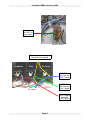
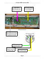
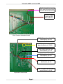
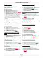
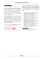
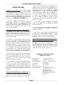
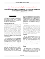
Lintronics MIDI converter LMC
MUSIC INC.
Lintronics, Franziska-Barbara-Str. 10, 91452 Wilhermsdorf, Germany
℡ +49 9102 999515 ↸ www.lintronics.de
[email protected]
LMC Installation Instructions
MIDI Input
wire from
the NOISE
switch
X
Cut the
four wires
X
X
Connect the
OSC1 and
EXT-Input
switches
X
EXT-Output from
the LMC board
wire from the MODULATION MIX pot
(was connected to
the NOISE switch
before)
EXT-Input switch
Page 1
TM
Lintronics MIDI converter LMC
wire from
the EXT-Input switch
NOISE switch
Cut the connections from
these pins to ground
Loudness
Filter
Oscillator
BEND-Output from the
LMC board
FILTER-Output from the
LMC board
CV inputs
VOL-Output
from the
LMC board
Page 2
Lintronics MIDI converter LMC
LMC board
mounted on the Contour Generator / Keyboard Circuit board
GLIDE wires, connected to the two free holes on the Keyboard
Circuit board
Minimoog rear view
MOD-Output from the LMC
board (remove the 1KOhm
and connect the two wires
instead of the resistor
MIDI input (pin view)
5
DIN 5-Input from the
LMC board (green)
short ground wire
from the LMC board
(black), near the
Lintronics logo
DIN 4-Input from the
LMC board (yellow)
Page 3
4
Lintronics MIDI converter LMC
Cut the trace between pin
21B and 22B of the Dual
Contour Generator board
DECAY-Outputs
from the LMC
board (brown)
Dual Contour Generator board
PITCH-Output from the LMC
board (grey), pin 9A
GLIDE-Outputs from the LMC
board (yellow), pin 7A/8A
GND-Input from the LMC
board (black), pin 2A
-10V-Input from the LMC
board (blue), pin 3A
+10V-Input from the LMC
board (red), pin 1A
GATE-Output from the LMC
board (brown), pin 6A
Keyboard Circuit board
Page 4
1
2
3
4
5
6
7
8
+10
Key CV
E3
4.7uF
MIDI In
Q1
R2
9
40
41
42
43
44
1
2
3
4
5
6
2
D/A Converter
150
12
13
CS
WR
1
OUT-1
3
3
2
R11
2K 1%
16
6
11
10
9
X
4
4
R6
R4 1%
100
R7
10.0K
2.0K
1%
U2B
MC33079
1%
13
14
15
12
1
5
2
4
Bend CV
7
LFO Out
Extern
6
7
C7
10nF
R9
820
S2
12
Mod.
Wheel
S&H / Buffer
S3
U2D
MC33079
U4D
MC33079
Filter
13
-10
L1
13
14
14
S6
R10
2.2K
12
-5
E4
4.7uF
C4
10nF
C9
10nF
Multiplexer
S8
2
1
5
4
2DP
13
2DN
8
0.1uF
C14
2A
P1
2K
+10
11
12
9
T2
BC327
5
1
7
-5
13
7
2
R13
15K
T1
BC337
U10B
4558
IN1
2
D1
+5
R21
47
1%
1
C15
1K
R18
C18
R16
10K
1%
0.1uF
4.7uF
E5
-10
C16
0.1uF
-5
-10
R19
10K
1%
4.7uF
E6
C19
0.1uF
12
IN2
16
D2
15
S1
S2
14
6
S4
S3
11
7
D4
D3
10
IN3
9
8
IN4
4
VEE
6
1K
R14
NC
3
4
3SP
3Y
3SN
R20
10K
R15
47
U10A
4558
3
Scale
3A
+10
0.1uF
C17
R17
10K
1%
+10
Glide
S11
Glide
S10
Gate
S12
Key CV
S1
U9
5
1SP
1DP
1DN
1SN
+5Volt
Power Supply
VCC
U8
4007
0.1uF
A
Decay
R12
470
GND
-5Volt
Power Supply
1A
GND
10
S9
+5
8
14
VCC
6
Decay
B
C13
0.1uF
3
MAX334
Switches
-10
A
MIDI Converter
for Minimoog
LINTRONICS 8-Apr-2013
1
C
LT3011/2
MIDI Thru
Option
B
(150-2.2K)
S4
15
Vref
S7
5
U4B
MC33079
INH
A
B
C
R8
Jumper
6
C5
10nF
3
5
-10
5
GND
Rfb
X0
X1
X2
X3
X4
X5
X6
X7
2
6
OUT-2
D
3
9
U3
4051
U7
LF351
8
270
DB0
DB1
DB2
DB3
DB4
DB5
DB6
DB7
+Vdd
+5
+10 C12
15pF
U6
MX7524
11
10
9
8
7
6
5
4
10
1%
R5
10.0K
1
S5
C3
10nF
C11
0.1uF
U2C
MC33079
1%
R3
12.7K
8
+5
GND
28
27
26
25
24
23
22
21
20
19
18
C
+5
VEE
1uF
C8
0.1uF
16
7
8
9
10
11
12
13
14
15
16
17
11
D1
4148
C6
10nF
U1
PC900
E2
RES
R/W
DS
AS
P35
GND
P32
P00
P01
P02
RL
3
C10
10nF
7
86E21
5
NC
P14
P13
P12
P11
P10
P07
P06
P05
P04
P03
NC
P24
P23
P22
P21
P20
P33
P34
P17
P16
P15
1
14
P25
P26
P27
P31
P36
VCC
XTAL2
XTAL1
P37
P30
NC
U5
4
10
U2A
MC33079
2
Volume
1
R1
220
6
39
38
37
36
35
34
33
32
31
30
29
2
8
1K
E1
4.7uF
U4A
MC33079
11
D2
4148
U4C
MC33079
7
C2
22pF
12MHz
J1.5
VCC
C1
22pF
D
J1.4
+5
4
+10
4
+5
2
3
4
5
6
7
8
Lintronics MIDI converter LMC
Owner Manual for the Lintronics Minimoog Interface (Copyright 1994)
Date: 02/10/2001 / Rev. 1.04
Run without MIDI:
The Minimoog works as a normal Minimoog. The only one difference is the MODULATION
MIX pot. If the pot is on NOISE position and the EXT INPUT switch is on the ON position the internal LFO of the interface is active.
NOISE is on the MODULATION MIX pot when the EXT INPUT switch is on the OFF
position.
Run with MIDI:
After you switch on the Minimoog the MIDI interface receives data bytes on channel 1. If
you wish to change the channel you have to send a program change (1 to 16) on MIDI
channel 1. It is a good idea to turn the modulation wheel to the center position, turn on the
GLIDE switch and turn off the DECAY switch that you can control them via MIDI.
Program Change Table
Program Number
Function
1
2
3
4
5
6
7
8
9
10
11
12
13
14
15
16
M -*M
M
M
M
M
M
M
M
M
M
M
M
M
M
M
switches the interface to MIDI-channel
switches the interface to MIDI-channel
switches the interface to MIDI-channel
switches the interface to MIDI-channel
switches the interface to MIDI-channel
switches the interface to MIDI-channel
switches the interface to MIDI-channel
switches the interface to MIDI-channel
switches the interface to MIDI-channel
switches the interface to MIDI-channel
switches the interface to MIDI-channel
switches the interface to MIDI-channel
switches the interface to MIDI-channel
switches the interface to MIDI-channel
switches the interface to MIDI-channel
switches the interface to MIDI-channel
17
18
M -*M
19
M
program change enable --> ON
program change disable --> ON (only program change 17
pass the filter to enable this mode)
velocity controls VOLUME
Page 5
1
2
3
4
5
6
7
8
9
10
11
12
13
14
15
16
Lintronics MIDI converter LMC
Program Number
Function
20
21
22
M
M
M -*-
after touch controls VOLUME
foot pedal controls VOLUME (Controller 7)
maximum VOLUME
23
M
24
M -*-
controller 2/4 controls VOLUME --> ON
(only, if VOLUME control is OFF)
controller 2/4 controls VOLUME --> OFF
25
26
27
28
29
M
M
M
M
M -*-
velocity controls FILTER CUTOFF
after touch controls FILTER CUTOFF
mod.-pedal controls FILTER CUTOFF (Controller 2/4)
mod.-wheel controls FILTER CUTOFF (Controller 1)
FILTER CUTOFF control --> OFF
30
31
M
M -*-
after touch controls Mod.-Wheel --> ON
after touch controls Mod.-Wheel --> OFF
32
33
M -*M
pitch bend range has +/- 3 semitones
pitch bend range has +/- 6 semitones
34
35
36
37
M -*M
M -*M
lower key priority
higher key priority
keyboard works normally
keyboard works inverted (higher key <=> lower note)
38
39
40
M
M -*M
mod.-wheel controls keyboard --> ON
mod.-wheel controls keyboard --> OFF
mod.-wheel set the LFO speed
push and hold a key on your master keyboard, turn on the
mod.-wheel and send program change 40. Now you can set the
LFO speed with the mod.-wheel of your master keyboard. After
you let go of the key the mod.-wheel runs as normal as before.
41
42
43
44
45
46
47
S -*S
S
S
S
S
S
LFO triangle
LFO sawtooth falling
LFO sawtooth rising
LFO square wave 50% pulse width
LFO square wave 25% pulse width
LFO square wave 12.5% pulse width
LFO Random (Sample & Hold)
Page 6
Lintronics MIDI converter LMC
Program Number
Function
48
49
50
51
52
53
54
S -*S
S -*S
S
M
M -*-
LFO positive
LFO negative
LFO speed 1/1
(approx. 6Hz)
LFO speed 1/10 (approx. 0.6Hz)
LFO speed 1/100 (approx. 0.06Hz)
LFO trigger --> ON (pressing a key resets the LFO)
LFO-trigger --> OFF
55
56
57
58
59
60
61
62
63
64
M -*M
M
M
M
M
M
M
M
M
MONO keyboard mode
POLY keyboard mode preset (value 1-8 in ROM)
POLY keyboard mode --> active at the 1. key
POLY keyboard mode --> active at the 2. key
POLY keyboard mode --> active at the 3. key
POLY keyboard mode --> active at the 4. key
POLY keyboard mode --> active at the 5. key
POLY keyboard mode --> active at the 6. key
POLY keyboard mode --> active at the 7. key
POLY keyboard mode --> active at the 8. key
(in the POLY modes it's possible to play max. 8 monophonic
synthesizers polyphonic. Preset is a value from 1-8 which is
burned in the processors EPROM. Normally this value is 1)
65
M
System reset (after receiving this program change the interface
needs 0.25 sec. time for accepting the following MIDI bytes)
M =
S =
-*- =
only MIDI data controls the function
the Minimoog mod.-wheel can use this function too
default values after power on
technical description:
Power supply
Key range
Pitch Bend range
Volume CV
Filter CV
LFO CV
+/- 10 Volt, 50mA
64 semitones C1 to #D6
max. +/- 6 semitones, 14 bit resolution
0 to 5 Volt
0 to 5 Volt
+/- 2 Volt triangle, sawtooth falling,
sawtooth rising, square wave 50%,
square wave 25%, square wave 12.5%,
Random
Page 7
Lintronics MIDI converter LMC
USER'S MANUAL
LINTRONICS MIDI CONVERTER FOR THE MINIMOOG
August 10, 1995 Version
DESCRIPTION
The LINTRONICS MIDI CONVERTER (LMC)
for the Minimoog consists of a dedicated microcomputer which is installed completely inside the
Minimoog chassis. Its input is a conventional MIDI
IN jack. Its outputs are a series of control voltages
and switches which are permanently connected to
the Minimoog circuitry. These control voltages and
switches enable you to use MIDI to control these
Minimoog parameters:
Low-note keyboard priority is in effect.
Pitch Bend messages create pitch bends over a +/- 3
semitone range.
Minimoog Amount of Modulation is controlled
by both the Minimoog's right-hand wheel and MIDI
Modulation Amount messages (Control Change #1).
MIDI control of volume and filter cutoff is not enabled.
Pitch (note)
Pitch Bend
Volume
Filter Cutoff
Amount of Modulation
Independent LFO for Oscillators and Filter
Glide On/Off
Decay On/Off
External LFO signal is a triangular wave of
about 6 Hz.
Minimoog Decay is switched on and off by MIDI
Sustain Pedal message (Control Change #64).
Minimoog Glide is switched on and off by MIDI
Portamento Pedal message (Control Change #65).
DEFAULT SETTINGS
When you first turn on your LMC-equipped
Minimoog, your instrument will perform exactly as
a normal Minimoog, with the following exception:
The new switch next to the MIDI IN jack determines what modulation signal will be active when
the Minimoog's MODULATION MIX pot is at the
NOISE end (full clockwise). When the switch is in
the NOISE position, the Minimoog works normally.
But when the switch is in the EXT LFO position,
the modulation signal comes from the LMC's onboard LFO (Low Frequency Oscillator).
Your LMC may be programmed with MIDI
Program Change messages #1 to #65. The laminated "Lintronics MIDI Interface Program
Change Table" which is included with your
LMC, summarizes what these messages do. As soon
as you first turn on your LMC-equipped Minimoog,
the following conditons are in effect:
MIDI messages are received on MIDI Channel 1.
Note-on and Note-off messages over the note range
#36 - #99 are recognized.
PROGRAMMING YOUR LMC
MIDI Program Change numbers 1-65 are used to
select the LMC‘s settings. Following is a complete
list describing the LMC settings that are accessed
through via Program Change messages.
MIDI CHANNEL:
PROGRAM CHANGE NUMBERS 1-16:
Selects which basic MIDI channel for the LMC will
respond to. Program number is the same as the
MIDI channel number that it enables (DEFAULT:
Channel 1).
PROGRAM CHANGE ENABLE/DISABLE:
PROGRAM CHANGE NUMBERS 17-18:
Determines whether or not the LMC will respond to
further Program Change messages. Program Change
17 enables the LMC to respond to subsequent Program Change messages, while Program Change 18
blocks all subsequent Program Change messages
except number 17 (Program Change Enable) and
65 (SYSTEM RESET).
Page 8
Lintronics MIDI converter LMC
VOLUME CONTROL:
PROGRAM CHANGE NUMBERS 19-24:
Selects the MIDI control source which will control
volume, as shown below:
19 - Note-on Velocity
20 - MIDI Channel Pressure (Aftertouch)
21 - MIDI Channel Volume (Control #7)
22 - Maximum volume - no MIDI control (Default)
23 - Either Breath Controller (Control #2) or Foot
Controller (Control #4).
NOTE: Program Change #23 is implemented
only if all other MIDI control of volume has
been disabled, by sending Program Change
#22, or by resetting the LMC to its power-on
default.
24 - Breath Controller (Control #2)/Foot Contoller
(Control #4) disabled
FILTER CUTOFF:
PROGRAM CHANGE NUMBERS 25-29:
Selects a MIDI control source to control the filter
cutoff, as shown below:
25 - Note-on Velocity
26 - MIDI Channel Pressure (Aftertouch)
27 - Either Breath Controller (Control #2) or Foot
Controller (Control #4) .
28 - Modulation Wheel (Control #1)
29 - No MIDI control of filter (Default)
CONTROL OF MOD AMOUNT BY AFTERTOUCH: PROGRAM CHANGE NUMBERS 30-31:
30 - MIDI Channel Pressure (Aftertouch) controls
amount of modulation.
31 - MIDI Channel Pressure (Aftertouch) does not
control amount of modulation.
KEYBOARD NORMAL/INVERSE:
PROGRAM CHANGE NUMBERS 36-37:
36 - Keyboard operates normally - pitch goes up as
you play higher keys. (Default)
37 - Keyboard is inverted - pitch goes down as
you play higher keys.
MOD WHEEL PRODUCES KEYBOARD GLISSANDO: PROGRAM CHANGE NUMBERS 38-39:
38 - Modulation wheel produces glissando
39 - Modulation wheel does not produce glissando
(Default)
MOD. WHEEL SETS LFO SPEED:
PROGRAM CHANGE NUMBER 40:
Hold a key, send Program Change #40, set the
LFO speed with your MIDI Modulation Wheel,
then release the key.
WAVEFORM OF ON-BOARD LFO:
PROGRAM CHANGE NUMBERS 41-47:
41 - Triangular (Default)
42 - Sawtooth Falling
43 - Sawtooth Rising
44 - Square (50% pulse width)
45 - Rectangular (25% pulse width)
46 - Rectangular (12.5% pulse width)
47 - Random steps, like Sample and Hold
LFO WAVEFORM POLARITY:
PROGRAM CHANGE NUMBERS 48-49:
48 - Waveform goes positive. (Default)
49 - Waveform goes negative.
PITCH BEND RANGE:
PROGRAM CHANGE NUMBERS 32-33:
LFO WAVEFORM SPEED RANGE:
PROGRAM CHANGE NUMBERS 50-52:
32 - Pitch Bend range is +/- 3 semitones. (Default)
33 - Pitch Bend range is +/- 6 semitones.
50 - High speed range ( 0.6 Hz to 6 Hz) (Default)
51 - Medium speed range (0.06 Hz to 0.6 Hz)
52 - Low speed range (0.006 Hz to 0.06 Hz)
KEY PRIORITY:
PROGRAM CHANGE NUMBERS 34-35:
WAVEFORM RESET:
PROGRAM CHANGE NUMBERS 53-54:
34 - The lowest of all keys that are on will determine the Minimoog's pitch. (Default)
35 - The highest of all keys that are on will determine the Minimoog's pitch.
53 - LFO resets whenever a new note starts.
54 - LFO does not reset whenever a new note starts
(Default).
Page 9
Lintronics MIDI converter LMC
KEYBOARD MODE:
PROGRAM CHANGE NUMBERS: 55-64:
Two keyboard modes are available: Mono and
Poly. In the mono keyboard mode, the LMC responds to all MIDI note-on messages, and then
'plays' the lowest key depressed or the highest key
depressed, depending on which key priority is selected. This is the mode that you would normally
select if you are using one LMC-equipped Minimoog in your MIDI system.
In the poly keyboard mode, an LMC responds to
every eighth MIDI note-on message. All program
change messages within the range #56-#64 turn on
the poly keyboard mode. The differences among
them are that each of these messages activates a different note in the eight-note cycle. Thus, up to eight
LMC-equipped Minimoogs can be hooked up to
form a polyphonic ensemble.
Here is a list of all the MIDI Program Change
messages that affect the keyboard mode.
55 - Mono keyboard mode - LMC responds to all
MIDI note-on messages (Default).
56 - Poly keyboard mode - LMC responds to one
of the notes in the eight-note cycle. The number of
the note in the cycle is preset, and is permanently
burned into the LMC's micro-processor. The normal
number is 1. (You can order an LMC microprocessor with any number from 1 to 8. For further information, call Big Briar's Customer Service Department.)
57 - Poly keyboard mode - LMC responds to the
first note in the eight-note cycle
58 - Poly keyboard mode - LMC responds to the
second note in the eight-note cycle
59 - Poly keyboard mode - LMC responds to the
third note in the eight-note cycle
60 - Poly keyboard mode - LMC responds to the
fourth note in the eight-note cycle
61 - Poly keyboard mode - LMC responds to the
fifth note in the eight-note cycle
62 - Poly keyboard mode - LMC responds to the
sixth note in the eight-note cycle
63 - Poly keyboard mode - LMC responds to the
seventh note in the eight-note cycle
64 - Poly keyboard mode - LMC responds to the
eighth note in the eight-note cycle
SYSTEM RESET:
PROGRAM CHANGE NUMBER 65:
Resets all settings to their power-on defaults.
Page 10
Lintronics MIDI converter LMC
USING THE LMC
HOOKING YOUR LMC UP: Your LMC-equipped
Minimoog may be used with or without a MIDI
controller. If you do not use a MIDI controller, you
will find that your Minimoog works exactly the
same as a regular non-LMC Minimoog, but in addition has an extra LFO which produces a 6 Hz triangular wave. (See DEFAULT SETTINGS above.)
If you use a MIDI controller that has only one
MIDI OUT, you will have to connect the MIDI IN
of your LMC to the end of the MIDI chain. If your
MIDI controller has more than one MIDI OUT, you
have the option of dedicating one of these outputs
just to control the LMC.
USING PROGRAM CHANGE COMMANDS: All
programming of your LMC is done through MIDI
Program Change messages. For this reason, it is desirable to use a MIDI controller that provides convenient means for generating program change messages #1 through #65.
In addition, you should ensure that your controller does not generate unwanted program change
messages. For instance, certain MIDI controllers require you to push two buttons to generate some program change numbers, but only one button to generate other program change numbers. In these controllers, you generate one program change when you hit
the first button and a different program change
when you hit the second button. Controllers that operate in this way are difficult to use with the LMC.
Many dedicated devices and computer programs
that read and display MIDI messages are available.
You may find that using such a device or program
will help you to know exactly what program
changes your LMC is receiving.
If your LMC receives the same MIDI message
stream as one or more other instruments in your setup, you will probably want to assign the LMC to its
own MIDI channel, so that program change messages which you intend to program the LMC will
not cause unwanted program changes in other instruments.
SETTING THE MINIMOOG'S CONTROLS: The
LMC does not autotune the Minimoog. Therefore,
you will have to tune the Minimoog when using the
LMC, just as you tune it when you use it normally.
The amount of the Minimoog's modulation is determined by the combined effect of the Minimoog's
Modulation Amount wheel and MIDI Modulation
Amount messages (Control Change #1) or MIDI
Channel Pressure messages. If you're using MIDI to
control modulation amount, then the Minimoog's
mod wheel should be full on. On the other hand, if
you want to use the Minimoog's mod wheel after
you use a MIDI modulation amount message
stream, then you should leave the MIDI modulation
amount at maximum.
If you wish to control the Minimoog's GLIDE
function from MIDI, then the Minimoog's GLIDE
switch should be on.
If you wish to control the Minimoog's DECAY
function from MIDI, then the Minimoog's DECAY
switch should be off.
If you want to use the LMC's LFO function, then
the Minimoog's MODULATION MIX pot should
be full clockwise and the toggle switch next to the
MIDI IN connector should be on EXT MOD.
USING THE MINIMOOG'S KEYBOARD AND A
MIDI KEYBOARD AT THE SAME TIME: If you
depress a key on your MIDI keyboard and a key on
the Minimoog keyboard at the same time, you will
generally not get a correct pitch. However, you can
play the MIDI keyboard and your Minimoog keyboard alternately, in which case you will get the
pitch of the last key that was depressed.
TECHNICAL SPECIFICATIONS
(LMC Circuit Only)
Power Supply:
Key Range:
Pitch Bend Range:
+/- 10 volts, 50 mA
64 semitones C2 to D#6
max +/- 6 semitones, 14 bit
resolution
Volume CV:
0 to +5 volts
Filter CV:
0 to +5 volts
LFO voltage output: +/- 2 volts
LFO waveforms:
Triangle, Rising Sawtooth,
Falling Sawtooth,
Square Wave 50%,
Rectangular Wave 25%,
Rectangular Wave 12.5%,
Random.
Page 11
Lintronics MIDI converter LMC
Note: The old version of the Big Briar instructions is different!
THE LINTRONICS MIDI CONVERTER KIT FOR THE MINIMOOG
-INSTRUCTIONS FOR INSTALLATIONFebruary 17, 2002 Version
HOW IT WORKS
Before attempting to install or use the Lintronics MIDI Converter (LMC) for the Minimoog,
please read the following Theory of Operation.
This information will help you to understand how
the LMC works with the Minimoog.
same points on the Minimoog's Contour Generator
and Keyboard circuit board, they perform the same
function. This means that the Minimoog's keyboard will perform normally when no MIDI noteon messages are in effect, but that you cannot use
the Minimoog's keyboard while the LMC is responding to one or more MIDI note-on messages.
NOTE ON AND NOTE OFF
PITCH BEND
The Minimoog is a monophonic analog synthesizer which is normally controlled from its keyboard. The keyboard has two outputs: PITCH and
TRIGGER. When one or more keys are depressed,
the pitch output (or pitch buss) delivers a voltage
that depends on the lowest key that is depressed.
When any key is depressed, the trigger output (or
trigger buss) voltage becomes +10 volts. When no
keys are depressed, neither of the keyboard busses
is connected to any voltage. The two keyboard outputs go to the Contour Generator and Keyboard
circuit board, which then processes them for use in
determining the Minimoog pitch and starting the
contour generators.
Two of the LMC outputs are called PITCH and
GATE. When the LMC receives a MIDI 'note on'
message, it produces a pitch voltage from -1.445
volts (MIDI note # 36, or C2) to +3.655 volts
(MIDI note # 99, or D#7). In addition, it produces
a gate voltage of +10 volts whenever a MIDI 'note
on' message for any note is received. When all
MIDI note-on messages have been followed by
matching note-off messages, then both the pitch
and the gate voltages are disconnected from the
LMC output. Thus, the pitch and gate outputs of
the LMC serve exactly the same function as the
pitch and trigger outputs of the Minimoog keyboard. And, since they are connected to exactly the
The BEND output of the LMC produces a voltage from approximately -0.55 volts to +0.55 volts
in response to MIDI pitch bend messages. This
output controls the Minimoog's oscillators through
a bridging contact on the 'Oscillator' control input
jack on the rear panel. Thus, when there is no plug
in this jack, the LMC BEND voltage is active;
when there is a plug in the 'Oscillator' control input
jack, the LMC BEND voltage is disabled.
LOUDNESS
The VOL output of the LMC produces a voltage from 0 volts to +5 volts in response to the
MIDI message that you've selected for volume
control. This output controls the Minimoog's amplitude through a bridging contact on the
'Loudness' control input jack on the rear panel.
Thus, when there is no plug in this jack, the LMC
VOL voltage is active; when there is a plug in the
'Loudness' control input jack, the LMC VOL voltage is disabled.
FILTER
The FILTER output of the LMC produces a
voltage of 0 volts to +5 volts in response to the
MIDI message that you've selected for filter control. The output controls the Minimoog's filter
Page 12
Lintronics MIDI converter LMC
cutoff through a bridging contact on the 'Filter'
control input jack on the rear panel. Thus, when
there is no plug in this jack, the LMC FILTER
voltage is active; when there is a plug in the 'Filter'
control input jack, the LMC FILTER voltage is
disabled.
thoroughly tested and calibrated. If you follow
these instructions carefully, and if your instrument
is a standard Minimoog that was built after 1971,
you should have no problem performing this installation successfully. Read the following instructions
carefully. The warranty will be void if you damage
the circuitry by improper installation or handling.
MODULATION AMOUNT
The MOD 1 and MOD 2 terminals of the LMC
form a variable resistor whose resistance is determined by the MIDI message that you've selected
for modulation amount control. These terminals
are connected in series with the output of the Modulation Mix circuit of the Minimoog, which feeds
the Minimoog's right-hand wheel. The right-hand
wheel of the Minimoog is still active. This means
that, when using MIDI messages to control modulation amount, you should set the Minimoog's
right-hand wheel all the way up.
LFO
The LMC contains a digitally-programmable multiwaveform LFO (Low Frequency Oscillator). The
LFO output is called EXT. A toggle switch next to
the MIDI IN connector on the back of the Minimoog enables you to switch in the LFO signal in
place of the Minimoog's noise modulation signal.
DECAY
The LMC Kit for the Minimoog contains the following:
•
•
In order to complete the installation, you will need
the following:
•
•
•
•
•
•
•
•
•
•
•
The two DECAY terminals of the LMC form a
switch which is opened and closed by the MIDI
Sustain Pedal control change message (#64). These
terminals are connected in series with the Decay
switch on the Minimoog left-hand controller block.
Thus, the Minimoog Decay switch should be off in
order for the LMC Decay function to work.
•
•
The two GLIDE terminals of the LMC form a
switch which is opened and closed by the MIDI
Portamento On-Off control change message (#65).
These terminals are connected across the Minimoog's glide control and switch. Thus, the Minimoog Glide switch should be on for the LMC
Glide function to work.
INSTALLING THE LMC KIT
ATTENTION: The components in your LMC Kit
for the Minimoog have been carefully built and
Electric drill with 5/64", 1/8", 3/16", and 1/4"
bits
Center punch (and a small hammer if necessary)
5/8" D. hole punch
Countersinking bit
#1 and #2 Phillips screwdrivers
1/4" and 5/16" nut drivers
Scissors
Small knife for scraping solder mask off circuit board traces
Small soldering iron (35 watts or less) and solder
Wire strippers
Electrical tape, or heat-shrink tubing and a
heat gun
MIDI keyboard or other source of MIDI messages, with a MIDI cable
Headphones or a monitor amplifier
The following tools may also prove useful:
•
•
•
GLIDE
Circuit board with MIDI 5-pin DIN connector
Small envelope with mounting hardware
•
Solder sucker
Voltmeter for checking and trouble shooting
Small wire brush to clean soldered
connections
Soft brush or small vacuum to remove metal
shavings
1. Remove the back cover of the Minimoog.
Remove all four of the plug-in circuit boards. Note
how the mounting hardware is used, so you reinstall the boards correctly. Place a rag or piece of
cardboard over the Minimoog's circuit board connectors, to keep metal shavings from falling into
the connectors.
Page 13
Lintronics MIDI converter LMC
2. Look at the LMC Kit Template. This clear
plastic sheet serves two purposes: it locates the
holes that you must drill, and it provides labels for
the switch and the MIDI IN connector. The holes
you must drill are a) a 1/4" hole for the toggle
switch, b) a 5/64" hole for the alignment key of the
toggle switch, c) two 1/8" holes for the MIDI connector's mounting screws, d) a starting hole (usually 1/4" or 5/16") for the 5/8" punch for the MIDI
IN connector itself, and e) two countersunk 3/16"
holes to mount the LMC circuit board. Note that
the three Minimoog output jacks are shown, to
show you how to position the template on the Minimoog.
3. Using sharp scissors, carefully cut along the
dotted lines that define the outline of the template.
Then position the template up against the Minimoog's output jack washers. Carefully line up the
centers of the switch and MIDI connector holes
with the centers of the Minimoog output jacks.
Then temporarily tape down the template.
4. Using the center punch, mark the centers of
the holes to be drilled. Remove the template. Drill
all the holes (the hole sizes are marked on the template). Take one of the 8-32 flat head screws out of
the hardware envelope. Countersink the two 3/16"
holes until the flat-head screw goes in just deep
enough so that it is flush with the mounting surface. Use your 5/8" hole punch to make the hole
for the MIDI connector.
5. Clean out all shavings from the Minimoog
chassis. One metal shaving in the wrong place can
cause a meltdown!
Minimoog. Place the indexing washer on the bushing. The washer's indexing tab should go into the
5/64" hole. Finally screw the second nut on the
bushing and gently tighten with a 5/16" nut driver.
Do not overtighten, as this may break the switch
bushing..
8. Using the 4-40 screws, lockwashers, and nuts
in the hardware envelope, mount the MIDI DIN
connector. Position the connector so the five contacts are toward the back of the Minimoog. The
mounting screws go in from the top; the lockwashers go between the nuts and the chassis.
9. Look at the back of the Minimoog 'WHITE PINK' noise selector switch. Refer to Figure 2.
Carefully desolder and remove the blue wire from
terminal 2 of the White-Pink switch. (This is the
wire that feeds the modulation signal to the 'noise'
end of the Minimoog Modulation Mix pot.) Solder
this blue wire to the free end of the blue wire on
the toggle switch that you've just installed. Place a
short length of heat-shrink tubing on the wires before making the splice,- or wrap the splice with
electrical tape after it is soldered. Finally, solder
the free end of the yellow wire (on the toggle
switch) to terminal 2 of the Minimoog White-Pink
switch.
10. Solder the free end of the white/black wire
to J1-2. Solder the free end of the white/green wire
to J2-2. Solder the free end of the white/yellow
wire to J3-2. Then position this cable so it runs
along the bottom of the Minimoog chassis, next to
the circuit board connectors.
6. Look at the three control inputs jacks of the
Minimoog. Refer to Figure 2. Remove the short
jumpers going from J2-2 to J2-3, and from J1-2 to
J1-3. Remove the 33K resistor that is connected to
J3-2. Remove the jumper that goes from SO1-1
(the wide prong of the S-trig input socket) to J1-2.
Add a jumper from SO1-1 to J1-3. Clean the solder
off J1-2, J2-2, and J3-2.
11. Look at the Minimoog Power Supply board
(The board with the aluminum heat sinks at the left
end). Find 'R57' (1K ohms) in the lower right corner of the board. Remove this resistor and clean
off the solder pads. Then take the short cable assembly with the two-pin connector and solder the
free ends of the violet and white/orange wires in
place of R 57. (See Figure 2.) Finally, re-install the
Minimoog Power Supply board.
7. Mount the toggle switch as follows: The
switch comes with two nuts, a lockwasher, and an
indexing washer. Position the first nut on the
switch bushing, about 1/8" from the switch body.
Put the lockwasher on the bushing. Place the
switch in the 1/4" hole that you've just drilled, so
that the slot in the bushing faces the back of the
12. Look at the Minimoog Contour Generator Keyboard board (the board with one set of 14 edge
contacts and one set of 22 edge contacts). Note
that there is a jumper on the component side, immediately above transistor Q12. Remove this jumper and clean off the solder pads to which it was
connected.
Page 14
Lintronics MIDI converter LMC
13. Turn the board over to the solder side. Note
that the set of 14 edge contacts is numbered 1A to
14A, and that the set of 22 edge contacts is numbered 1B to 22B. Scrape the 'solder mask' off a
small area of each of the traces going to edge contacts 1A, 2A, 3A, 6A, 7A, 8A, and 9A. The
scraped areas should be about 1/4" long, and
should be near, but not on the gold plating of the
edge contacts. Tin (solder-coat) each of these
areas.
14. Solder the free ends of the nine-wire cable
to the tinned areas that you have just prepared, as
follows:
RED
GREEN
BLACK
GREY
BROWN
YELLOW
PURPLE
to 1A
to 2A
to 3A
to 6A
to 7A
to 8A
to 9A
Solder the free ends of the orange and blue wires
to the two pads to which the removed jumper (See
step 12. above) was soldered. Clean and inspect all
connections. Finally, dress the cable so it tends to
run along the tops of the contact fingers.
15. Mount the LMC circuit board as follows:
Place one 8-32 x 1/4" screw in each of the countersunk holes which you have drilled on the top panel
of the chassis. Position the LMC circuit board next
to the Minimoog power supply board, with the
components facing out and the mounting brackets
facing up. Put a #10 fiber washer over one of the
brackets and drive the appropriate screw into the
bracket. (The purpose of the fiber washer is to
space the bracket away from the screw head so that
the screw doesn't 'run out of threads'.) Do the same
thing with the other screw. Tighten each screw
firmly.
18. Re-install the Oscillator board and the Filter-Amplifier board.
19. Your LMC installation is now ready for a trial run. The following quick checks will indicate
whether or not your installation is operating properly. After connecting a monitor amp and turning
the Minimoog on,
a) Play the Minimoog keyboard. It should play
normally.
b) Turn up the modulation wheel, set the MODULATION MIX knob to 'Noise', and set the OSCILLATOR MODULATION switch on. Press a key
and listen to the modulation. As you switch the
LMC toggle switch back and forth, the modulation
should alternate between noise (the normal Minimoog function) and a triangular wave modulation of
about 5 Hz (the LMC Low Frequency Oscillator).
c) Connect the MIDI OUT of your MIDI controller to your Minimoog's MIDI IN. Set your MIDI
controller to MIDI channel 1. Playing your controller's keyboard should have the same effect as playing the Minimoog keyboard.
d) Your controller's pitch bender should bend the
pitch of the Minimoog. With the Minimoog mod
wheel turned all the way up, your controller's Mod
Amount wheel should control the amount of modulation in the Minimoog.
e) With your Minimoog's DECAY switch off,
depressing your controller's Sustain pedal should
cause the Minimoog's tones to sustain. With your
Minimoog's GLIDE switch on, your controller's
Portamento pedal should cause the Minimoog's tone
to glide.
If you observe all these conditions, you may proceed to a more thorough exercise of the LMC's
functions.
16. Mate the two 2-pin connectors. Mate the
two 3-pin connectors. Mate the two 4-pin connectors. Position them toward the front panel, so that
they will not tend to touch the oscillator or the filter-amplifier boards.
17. Mate the 9-pin connector on the Contour-Keyboard board with the mating connector on the
LMC board. Then re-install the Contour-Keyboard
board.
Page 15